
For past sins!
I realized as I was making up a quick sketch of all the GIB controlled electrical components (with the addition of the LED lit fuel site gauges) that I should account for the canopy locking rod & latches. I stumbled upon a discovery that shows yet another faulty assumption on my part, and I’m not sure exactly how I missed it.
The bottom line is that I found that the midpoint canopy latch is supposed to be –as per plans– situated at the front business area of my roll bar. I played around with it for a while, but realized I just had to bite the bullet and will have to move the middle canopy latch about 1.4″ forward. I’ll probably adjust the aft latch a hair forward as well, but at least now I know. Amazing that just this nth order affect took me about an hour to track down (well, technically over 2 years to track down!).
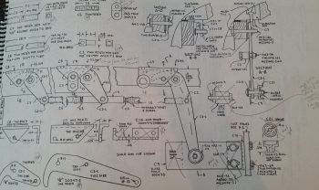
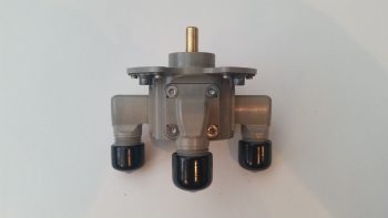
I then decided to do something different for a bit, other than fiberglass, so I sat down for a good 45 minutes and swapped out my Andair fuel selector valve’s straight fittings for the 90° fittings I ordered a while back.
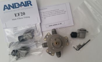
There’s no real directions as far as torque specs or anything on mounting these 90° fittings, so I just dove right in after checking Andair’s website and any available documentation I could get my hands on. It take a bit of an oomph to get the straight fitting off & out of the fuel selector valve once I removed the screws, especially since I was being a bit cautious with this first one.
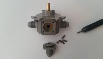
I then put the new 90° fitting in place and it fit perfectly. As you can see by the tools I added into each pic, the original screws were hi-torq screws, while the new 90° fittings came with an allen key for mounting the new screws.
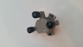
I then swapped out the other 2 straight fittings for the 90° fittings and those went on smoothly as well.
Here’s an underside “defensive crab” shot . . .
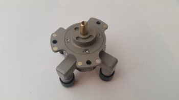
And the “running crab” shot!
I then set my sights on getting the front fuel sump “Leading Edge” 3/8″ Nylaflow tubing installed. This tubing will serve as a hidden electrical conduit to get the left GIB armrest comm wires over to the right side and up to the intercom, and also the left side Atkinson fuel site gauge LED wires over to the small wire bundle on the right side as well.
I started off by taping the 3/8″ Nylaflow tubing in place, then gluing it place with multiple dabs of 5-min glue.
After the 5 min glue cured, I then whipped up some micro and micro’d the gaps on the top and bottom side of the Nylaflow conduit.
I then laid up 1 ply of BID over the fuel sump “LE” 3/8″ Nylaflow electrical wire conduit.
Jumping ahead a few hours later, I then pulled the peel ply and cleaned up the layup. I think I will need to follow up with about 3 x 6″ layups (left, middle, right) to finish off this task.
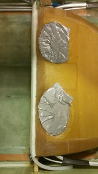
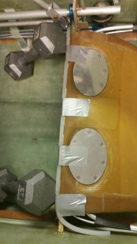
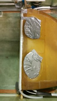
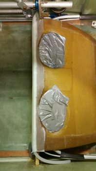
I also cut up some urethane foam blocks and shaped them into a hexagonal pyramid shape with a flat top for the sump’s low fuel sensor covers. I was going to do something more fun, like some big hex bolt looking covers, but I realized that if it had a flat surface on it than the GIB might mistake it for the sump top when climbing in and put all their weight on it . . . not good! Thus, I needed the covers to slant so while climbing in, any passenger who tried to use it as a step point would quickly realize it’s not as their foot slid off of it. Better the GIB have a bit of a surprise stepping-in wise than snap off one of those sump low fuel level sensors . . . especially with a worst-case scenario of causing a fuel leak into the cockpit!
Once I got the foam shape down (again, not perfect . . . oh, well — let’s stuff them where they work fine but no one can see them!) I taped the foam forms to the work table. I only used a round of duct tape on these forms, so no clear packing tape. I then laid up 2 plies of BID over each form and left them alone to cure.
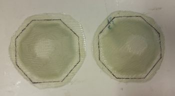
After cure, I popped them off –nice & EZ with these types of forms– and gave them a quick trim (below).
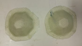
I then took my original outline that I made up a few hours ago, added a 1/4″ to the perimeter and then marked up the sump low fuel sensor covers for trimming. It’s way too late to trim tonight with the noise, so I’ll trim and sand them tomorrow.
Tomorrow I’ll continue on working on finalizing the fuel sump associated components, with an actual & very probable soldering of the sump low fuel sensor wires. Again, I’ll also continue to work getting all the GIB area stuff squared away.