
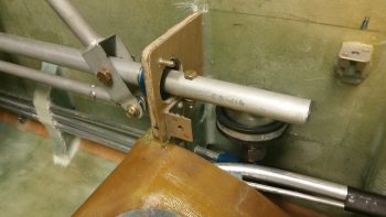
I started off today by pulling off the right GIB armrest to reveal a nicely floxed in place forward mounting tab. It is however, a bit too close for comfort to the control tube bearing’s bottom mounting bolt, so some judicious grinding away of some flox and maybe just a hair of the bracket on the outboard side will be in order.
As for the oil heat system, I have a couple things to note before I start on the discussion of my latest build tasks. First off, since the oil heat mod is of course not discussed in the Long-EZ plans, there’s not exactly an obvious place to put it categorically. I may break it out later in say a Chapter 27 – Environmental Controls or something, but for now, since the oil pump (and the now superseded fan) is electrical, I have it on a subpage in Chapter 22 – Electrical. Clearly much –if not the majority– of the oil heat system is not electrical, but that is where it resides topic-wise for now.
Secondly, just a point to say I’m still having camera issues since I thought I had a few more good pics of this process, but they turned out to be crap. So, we’ll move on with those decent pics I do have…
I cleaned out the foam form innards from the ram air intake expansion chamber top and 90° transition 1-1/2″ diameter port. The port will traverse through the sidewall into the main cabin just below the left longeron & just aft of the pilot’s seat back. For the 1.5″ diameter port, I looked all around for something that would make a good form, and eventually ended up using an Ibuprofen bottle since it was exactly 1.5″ in diameter. After taping it in place I could tell it was going to work perfectly!
After removing the foam, I spent a good 30 min. sanding the inside of the top transition chamber to smooth it out.
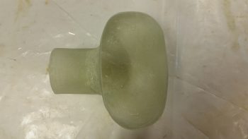
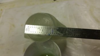
Again, here’s a shot of the 1.5″ ID opening. After leaving the expansion tube, all the ductwork will be constructed with the same cross-section capacity as 1.5″ SCAT hose.
I then prepped two 1″ wide x 10″ long 1-ply BID prepreg setups to glass the top transition piece onto the inlet/transition chamber body. I mixed up some MGS epoxy with fast hardener and then applied a thin film of fresh epoxy around the ends of each piece that would get glass.
I then wet out the prepregged BID and laid up the first ply with the seam on the outside of the two joined pieces (opposite the 1.5″ opening). I then laid up the second ply opposite of that with the seam right under the 1.5″ round opening.
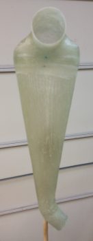
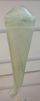
I then cut a 1″ peel ply tape down the middle and peel plied just the edges of the newly laid up BID. After about 30 min of curing, I then set the glassed assembly in the top of an open jug and put it in front of a heat lamp for about 30 min each side. I had to take the shot below since I couldn’t help but notice how much it looked like a Cobra ready to strike (which I have been face-to-face with, but alas, that is another story!). With fast hardener that did it for a workable cure cycle.

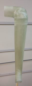
I then pulled the peel ply and cleaned up the edges of the glass. Here’s the new single-piece ram air inlet, expansion chamber and transition port ready for install.
I did have getting the wires soldered up for my sump low fuel level warning sensors as a goal to complete this evening, but I simply ran out of time. I will continue to work the final sump tasks, the oil heat/air system and the GIB area taskers during this next week.