
Today I started out by pulling the peel ply and cleaning up the side layups on the inside of the fuel valve pedestal base. I was going to layup the entire rest of it, but then determined that since I had decided to use thin-walled 1/4″ aluminum tubing to make up the top rounded edge that I needed an inside wall to create the “U” shaped channel, or rounded groove, along the top edge of the pedestal base.
So I glassed the aft inside wall and just as I did with the side walls, dug the foam out of the edge of the thigh support plate below and filled with dry micro. I then laid up 1 ply of BID overlapping slightly onto each of the previous interior sidewall layups.

I then put the layup under a heat lamp so that it would cure even more quickly, which it did. A little over an hour later I pulled the peel ply and cleaned up the layup.
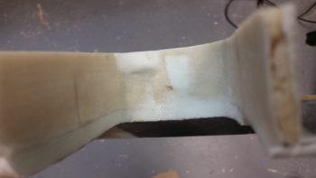
I then sanded the top of the pedestal base to ensure the top edge was even all the way around. I then double checked the fit of the thigh support with its newly attached fuel valve pedestal in place around the fuel valve bracket.
I then spent a good half hour bending and shaping a piece of 1/4″ 3003-0 Versatube to create the top edge of the fuel valve pedestal base. I considered using Nylaflow, but it’s really hard to get it to straighten out. I also considered just shaping the foam by hand, but I changed my mind in having a bit higher edge around the fuel valve bracket, so I figured the aluminum tubing was very light and would fit the requirement nicely.
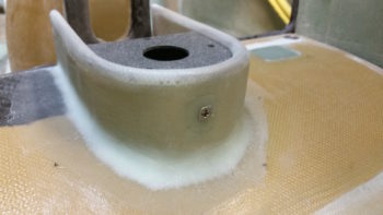
I failed to get any pics of the my ensuing tasks, but after I ensured the fit of the 1/4″ tubing was correct I then set it in place and filled in the gaps with micro and then glassed over the entire pedestal base with 1 ply of BID. I overlapped the BID ply onto the thigh support cover top about a half inch. When the layup was done I then peel plied it.
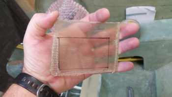
One question I had to answer was what to do on the front side of the fuel selector valve bracket, where its 6 attach screws reside. Since this area will be the floor to my little impromptu bin –when required– I figured I would simply take some spare glass I had kept around for just such purposes, make a small insert plate, and then simply use a few dabs of RTV Silicon to keep it in place until such time as I may need to remove the fuel valve bracket.
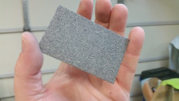
I found just such a piece of glass in my spare parts bin that looked to be about 3 plies thick. I marked out (amazing how clear this stuff is btw!) the dimensions of the cover plate on the glass piece.
And then sanded it, painted it with 2 coats of darker granite paint, then hit it with a couple coats of clear (not all in one shot, I’m jumping ahead with the pic below).
While the pedestal base layup was curing under the heat lamp, I then cut a piece of 1/16″ thick angled aluminum to create a support bracket tab that I’ll attach a nutplate to in order to allow me to secure the aft end of the cantilevered fuel valve bracket to the aft wall of the fuel valve pedestal base on the thigh support.
Here’s a closer up view of the fuel valve bracket screw support tab.
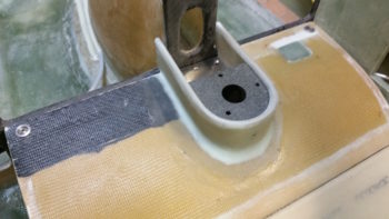
By this point the pedestal base layup was cured, so I pulled the peel ply and cleaned it up. I then spent a good half hour fitting the thigh support with its newly attached fuel valve pedestal in place around the fuel valve bracket. With the extra ply or 2 of BID on the inside of the pedestal base wall, I had to do some aggressive sanding in spots and even resorted to filing a bit of the edges of the fuel valve bracket in some spots to get things to fit! I underestimated how much clearance I would have so the fit was TIGHT! But I eventually proved myself smarter than these inanimate objects and won! ha!
I then drilled a small pilot hole for the fuel valve bracket screw support tab. I was off just a hair so I ended up making the hole bigger to use a #8 screw versus my originally planned #6 screw. With my hole drilled, I then drilled and riveted the #8 nutplate into place on the front side of the fuel valve bracket screw support tab.


After beveling the hole with a countersink, I then tested out a screw to see how it fit. I think this should do the trick nicely! Also, while the pedestal base layup was curing I primed & painted the fuel valve bracket, as you can see in this pic.
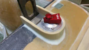
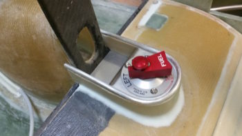
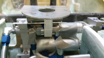
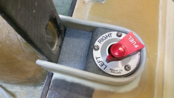
Here’s a shot of the painted fuel valve bracket in its thigh support pedestal.

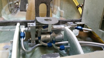
I quickly mocked up the fuel valve top assemblies (no actual valve here) as well as the forward screw cover plate to see how it was all looking so far. I’m liking it!
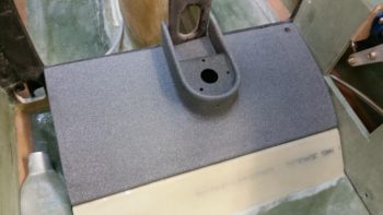
I then sanded down and prepped the thigh support cover for a couple of lighter coats of primer. Here’s the results after the primer dried.
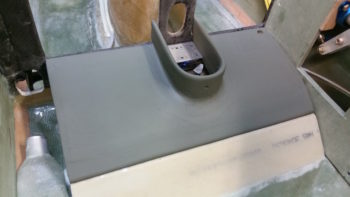
Then, for the grand finale of the evening, I hit the thigh support cover with a couple coats of the dark granite paint. I have to say, I really like my interior paint scheme so far.
Tomorrow it’s supposed to rain, but if I can I’ll sneak in a few coats of clear on the thigh support cover. I’ll finish getting the fuel selector valve and pedestal squared away, then move on to figuring out the left armrest console. I will also try to sneak in finishing the wiring on the Dynon intercom on the instrument panel mockup.