
Seriously!
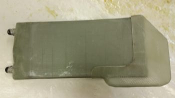
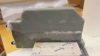
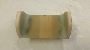
Today I started by pulling the peel ply off the heat exchanger bottom duct and cleaning it up.
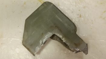
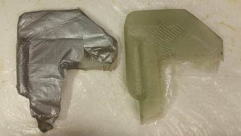
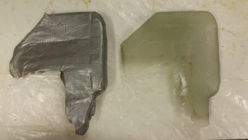
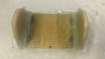
Here’s the inside foam that I never got a pic of before I taped it up. Just after I took this pic I dug it out of there.
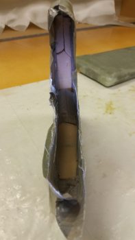
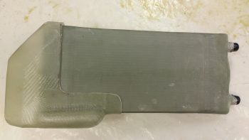
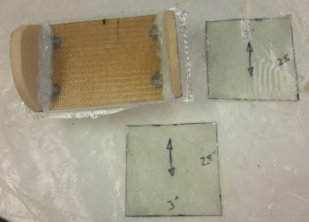
Here’s a couple shots of the tape (with the foam removed!) that I used as the form and the actual bottom duct piece.
I then marked up the heat exchanger bottom duct for trimming with the Fein saw.
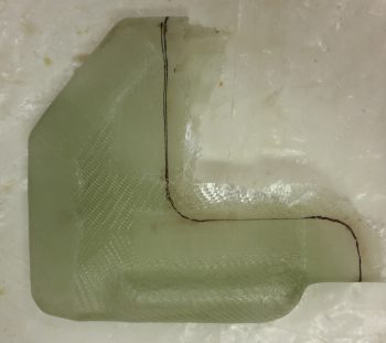
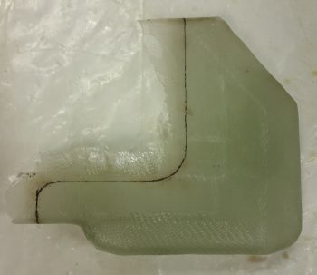
I then trimmed the bottom (outlet) heat duct with the Fein saw.
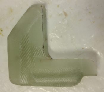
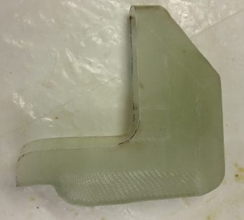
And then placed it back onto the heat exchanger cover to test the fit. So far all looks great!
I then placed it inside the cockpit where it will sit once installed in the plane. Again, the fit and finish are just right and all is a go at this time.
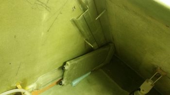
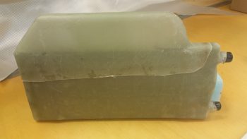
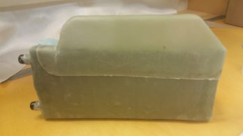
I then spent a good hour+ shaping a piece of urethane foam as the form for the heat exchanger top duct, and then taping it into place. Again, the angle you see at the corner of the heat exchanger is the contour of the back of the pilot’s seat.
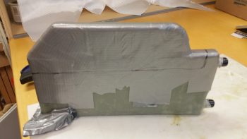
I offset the inlet and outlet of the heat ducts so that the inlet to the heat exchanger cover enters in the top aft part of the heat exchanger whereas the outlet exits out of the forward bottom part of the heat exchanger. This offset maximizes the amount of time the air “sees” the hot oil-heated surfaces of the heat exchanger before exiting to warm up the cabin.
Also, I needed space in the inlet duct that runs from the main air feed into the heat exchanger for a heat restrictor butterfly valve. This valve will allow me to keep the air out of the heat exchanger until the oil has time to heat up the heat exchanger and provide warm air. Otherwise, once the valve upstream that redirects the outside cold/cool air is turned to heat, if the air is really cold and the engine oil isn’t up to temp, then that would make for a really cold “heater”!
I then glassed the heat exchanger top duct with 2 plies using a bunch of scrap UNI. I then peel plied the layup.
I then spent a good 45 min playing around with the configuration of the oil heat pump to see exactly how I was going to mount it. The manufacturer says it’s best to mount it with the mounting plate in the horizontal position, but they didn’t say that one or the other side had to be up. So… I’ll be mounting it with the mounting plate in the horizontal position, just with the mounting bolts facing down. In addition, I’ll be mounting the oil heat pump in the hell hole, at the bottom of the GIB seat just behind & under the round access hole in the GIB seat.
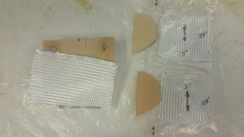
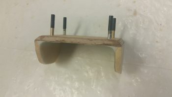
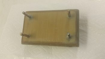
I settled on using my original 1/4″ Finnish Birch plywood mounting base, upside down, with a 1/4″ piece of foam on the top of each end of the wood base. With the foam end pieces in place, it would make a Π shape, only flipped upside down to this symbol shown. If I shaped each end foam piece to allow for the aft leaning GIB seat & the curve of the back of the seat, I could get all the 3 sides to contact the aft side of the GIB seat. I could then flox & glass all these 3 sides (2 vertical, 1 horizontal) to the aft side of the GIB seat for a nice, strong oil heat pump mounting bracket.
After figuring all the above out, I then spent another half hour finalizing the shape of the foam upright that will connect the sides of the 1/4″ plywood plate to the aft side of the lower GIB seat. I used a scrap piece of the urethane foam to dial in the shape, and then once I got the shape set I transferred it to 2 other scrap pieces of foam and cut out the foam end pieces I would use on the actual oil heat pump mounting bracket. To really put all you OCD/anal retentive types into an uncontrollable tailspin, get this: I used one piece of 1/4″ H45 Divinycell foam on one side and a piece of 1/4″ H250 Divinycell foam on the other. I bet that’ll keep you cursing me when you can’t sleep for the next month thinking about it! ha!
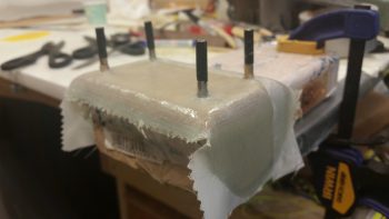
I then got my glass all sorted out for glassing the top side of the oil heat pump bracket. I prepregged 2 sets of 3 ply glass using a pair of the gazillion BID triangular pieces you end up with during these builds for each ply of BID. The schedule for the prepreg setups are BID-UNI-BID with the UNI perpendicular to the bottom edge of the side foam pieces. The single ply of BID on the top of the 1/4″ plywood bracket [that I previously floxed the 4 mounting bolts into] is for an initial ply of BID atop this wood base.
I made up just enough MGS 335 epoxy with fast hardener to glass the 1 ply of BID on top the 1/4″ plywood base. As the layup started to get tacky I then floxed the 2 foam end pieces into place, ensuring their outboard edges were aligned with the sides of the 1/4″ plywood.
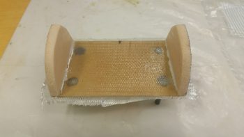
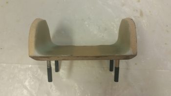
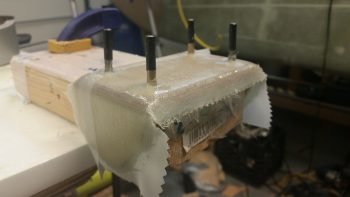
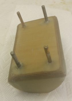
Here’s another shot of the oil heat pump mounting bracket. You can see that I taped up the bolts to protect them. Also, up until today I would have called this as the oil pump bracket being upside down, but now it is actually right side up. Also, since I had just a hair of epoxy left over, I went ahead and made up some wet micro and micro’d the inside faces of the foam end pieces.
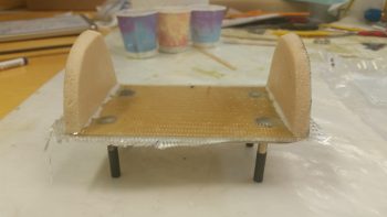
I then made up some more epoxy with fast hardener and wet out the prepreg setups. You can see I labeled the prepreg setups with arrows so I know the direction of the UNI cloth, which will actually get laid up 90° to how their shown here. I also whipped up some flox, which you can see that I used to put fillets in the corners between the foam and the wood base that I just laid up a ply of BID on top of. At this point, the BID was still very much tacky, but was quickly on it’s way to curing.
I then laid up the prepregged 3-ply glass setups, 1 on each side and squeegeed out the air in short order with the top prepreg plastic.
I then peel plied the entire top inside glass of the oil heat pump bracket with a piece of 3″ wide peel ply tape. It looks like I added a lot of wet epoxy, but in reality the epoxy was getting really tacky since it was fast hardener, and went it on like syrup vs wet epoxy. It still did its job however in wetting out the peel ply, it just took a bit more “coaxing!”
And yet another shot of the glassed & peel plied top/inside layup of the oil heat pump mounting bracket.
I then took a break to eat dinner and upload a bunch of these pics to this blog. When I returned the laid up oil heat pump glass was cured to at least a good 90% I’d say. I razor trimmed and easily pulled the peel ply and the layups looked good.
Here’s a couple more shots of the cured top/inside glass on the oil heat pump mounting bracket.
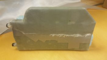
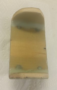
I then prepped a 4-ply prepreg setup for the bottom/outside layup for the oil heat pump mounting bracket. The layup schedule for this glass, starting from the bottom ply up was UNI-BID-UNI-BID. Both UNI plies were biased so their fibers ran straight from the top of one side, around the bottom, straight up the other side to provide a nice cradling type strength to the layup.
After I glassed the bottom/outside of the oil heat pump mounting bracket, I then of course peel plied it.
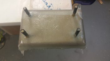
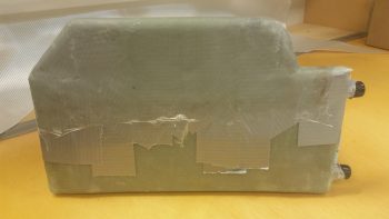
Here’s another couple shots of the glassed bottom/outside of the oil heat pump mounting bracket.
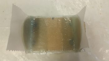
By this point in the evening, the heat exchanger top duct layup was cured so I then pulled off the peel ply.
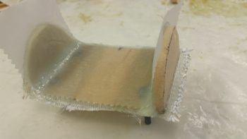
I then removed the whole assembly from the heat exchanger (forcibly!), removed the tape and foam from the inside of the top duct piece, and then quickly trimmed the top duct piece’s edges.
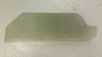
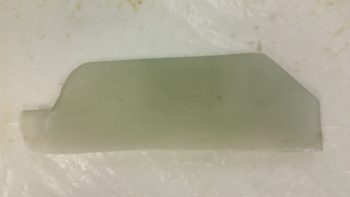
I then set the top duct piece back onto the heat exchanger to test the fit. It looks good and I don’t see any issues at this time. It’s way too late to fire up the Fein saw and trim this duct piece tonight, but I will get it trimmed within the next day or so.
In the amount of time it took me to write all the blathering above, when I went down to check on the oil heat pump mounting bracket bottom/outside glass layup it was cured. So I spent a good 15 min cleaning it up so I could knock it out and include in tonight’s blog.
These pics below kind of make it look like a dead bug, but here’s the cured bottom/outside layup on the oil heat pump bracket.
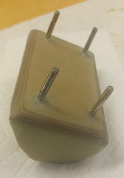
And here’s another shot of the top/inside of the bracket to see how the two sides came together.
Tomorrow I won’t get any building done since I’m spending the day with some friends who are moving out of the area in a few weeks. I will be back on the build hot ‘n heavy on Monday though.