
Oil heat that is!
Again, the Chapter 22 thing might be throwing you off a bit since it’s electrical, but currently that’s where I have my oil heat system. Thus, any discussion on the major ventilation system in this bird is married to the heat system, and ends up in Chapter 22. Weird huh?! Yep, well, nothing about building Long-EZ’s can be considered normal!
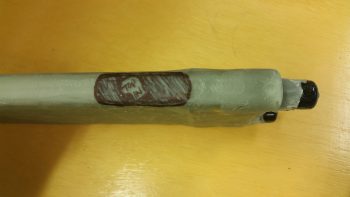
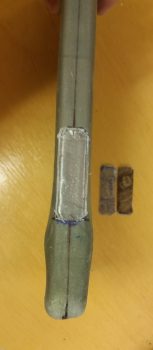
I had to run over to Andrews AFB to scarf up some money out of one bank to transfer to another bank for my upcoming purchase of the GRT EFIS I ordered under the discount that GRT offered for Sun N Fun 2017. Since Andrews requires some Interstate/Freeway/ Motorway driving, I decided to test out my ventilation/heat system ram air inlet. So I drilled a couple of holes into some chip board and then zip tied the inlet to the board. Then I duct taped the zip ties to ensure they wouldn’t slide off.
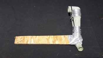
I think it’s ready to go!
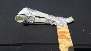
I then tested it out a bit in my driveway to ensure I wouldn’t kill, maim, hurt or embarrass myself . . . or anybody else for that matter.
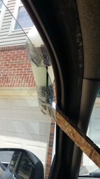
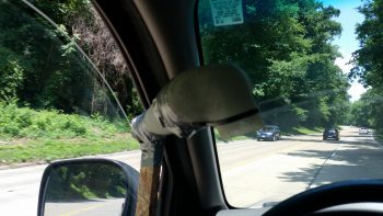
I quickly realized from messing around with it above, that the inlet needed to be straight into the wind as best possible, but the angle for the rest of it really didn’t matter. Regardless (or “Irregardless” for Joe Coraggio!) at around 65 mph I was getting pretty good airflow coming through. But then when I would push my hand up against the outlet I could pretty much shut down the flow.
So, quick assessment is that it seems to have decent airflow, but not good pressure. And in this game sports fans, pressure is what it’s all about. Looks like it’s back to the drawing board on this baby! [Plus, I’ll do some more detailed testing . . . I got some ideas!]
After arriving back home I quickly got into the shop with the intent of getting the 2-ply BID base reinforcement layup for the oil heat pump mounting bracket layup glassed onto the aft side of the GIB seat. I sanded down & prepped the area for the layup.
Then I prepregged 2 plies of BID, measuring 3″ x 8″, and wet it out with MGS 335 and fast hardener.
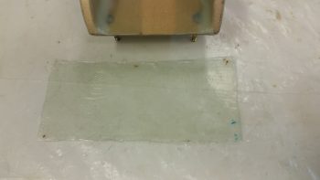
I then glassed in the 2-ply layup and peel plied it.
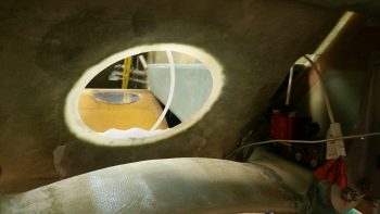
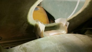
Here’s another shot at an angle to help with the exact orientation of this layup.
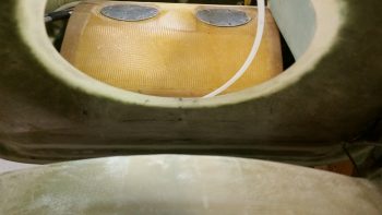
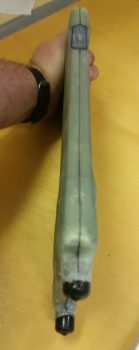
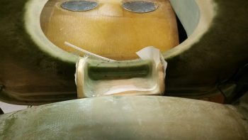
While the oil heat pump mounting bracket base reinforcement BID curing I then trimmed up the heat exchanger top duct piece.
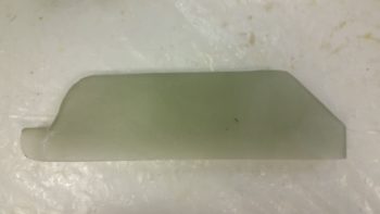
I then test fitted the heat exchanger top duct piece back on the heat exchanger.
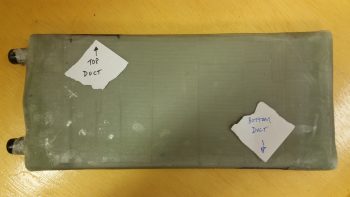
With both top & bottom ducts glassed, I could then verify the exact spots where the heat exchanger top & bottom inlets would go, given their dimensions match the ducts’ dimensions of 0.75″ x 2″.
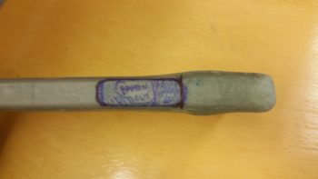
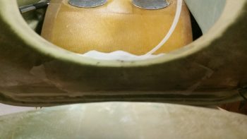
Again, for better understanding where the heat exchanger ducts are located, I identified them with a couple pieces of paper.
I then took a few minutes to mark up the lines along the entire perimeter edge of the heat exchanger cover to split the case in two and remove the heater core with all its protective tape, etc.

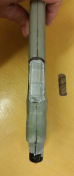
First though, I cut out the heat exchanger duct inlets on both the top & bottom (inlet & outlet).
After a fair amount of pulling, prying and practicing my “How to converse with Sailors” speak . . . and not to forget the requisite injury, I finally got one side off of the heat exchanger core.
Following the shampoo mantra . . . ok, the “repeat” part . . . I was finally able to get the other side pried off as well.
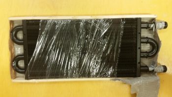
I then got to work deconstructing the protective barrier that Stacey had helped me construct (could this be why it was so difficult to remove?! . . . just kidding!). I took a fair number of pics on this process since I didn’t take any as we applied the protection before.
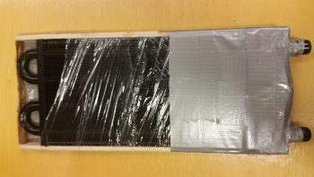
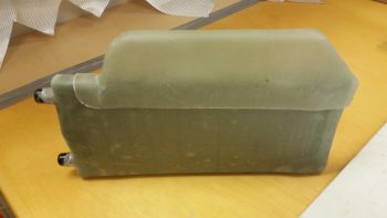
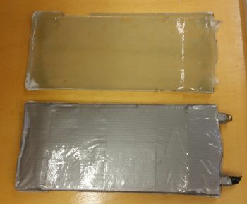
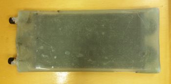
Here’s the final protective tape ensemble with the top & bottom 1/4″ wood caps that all served to protect the heat exchanger core while it was completely covered with glass.

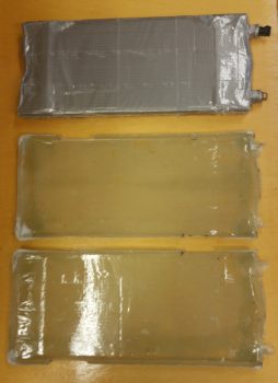
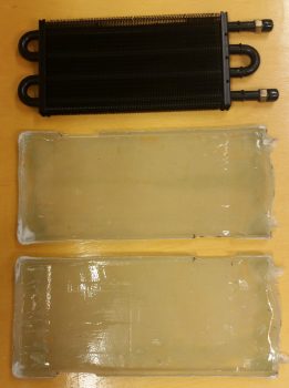
Finally, here’s the heat exchanger core with the two halves of the heat exchanger cover.
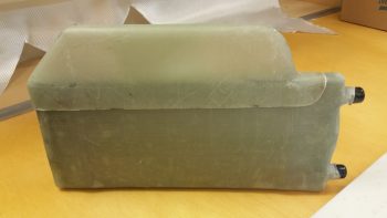
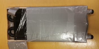
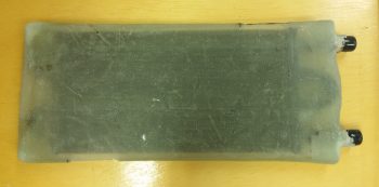
I then set the heat exchanger into one of the halves of the cover.

And then checked the fit of the heat exchanger core inside the cover. Ahh, it’s awesome when a plan comes together!
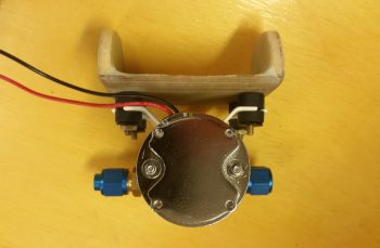
Although I had mounted the oil heat pump to its mounting bracket much earlier in the evening, my last official build task of the evening was to flox and glass the mounting bracket to its location on the lower aft side of the GIB seat.
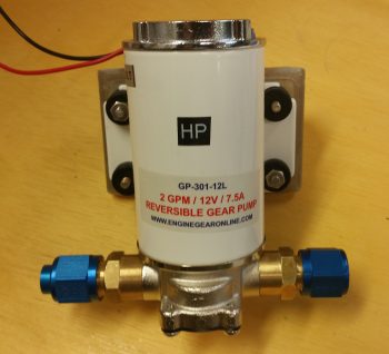
Before I get into that though, here’s a good shot (aft side) of how the oil heat pump will attach to the mounting bracket.
I pulled off the fittings and taped up the exposed areas of the heat pump as it sat on the mounting bracket. I’m floxing & glassing the mounting bracket into place with the oil heat pump mounted to it to ensure clearance for the pump on both the forward and aft sides.
Although my off-center pic makes it appear more askew than it actually is, I must admit that during the initial mounting process of this thing, it did end up skewed off center about 0.070″ and is higher on one side by about 0.030″ . . . but that’s why we call it the hell hole right?! (As I told Dave Berenholtz: “Loaded up with flox on the edges of course this guy was like trying to balance a fish on a greased hard boiled egg!”)
I do have one more set of BID tapes to do on the bottom after the 2 sets of outboard vertical, 2 sets of inboard vertical, and 1 set of topside horizontal BID tapes cure.
I took this shot at an angle for as good as view as we can get of the side layups, in the hell hole and all!
The layup schedule I used was a 3-ply BID tape on each outboard vertical junction (the foam tabs & seat back), with a 2-ply BID tape on the inboard vertical junctions (inside surface of foam tabs & seat back), and a 3-ply BID tape on the horizontal junction (1/4″ plywood bracket & seat back). Tomorrow, I’ll do a 3-ply BID tape across the bottom intersection with the seat back. Moreover, the 2-ply vertical junctions have a lot of overlap in the interior corners, thus there’s a good amount of “5-ply” BID in the corners.
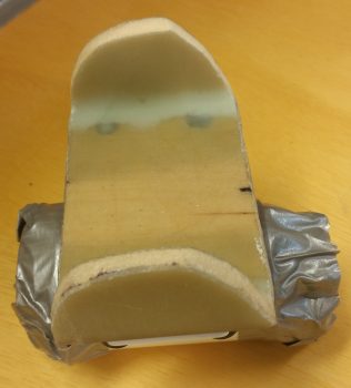
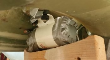
Finally, I wanted to show you all how I secured the pump/bracket assembly in place while I floxed & glassed it up. What you can’t see in this pic is that the wood support is actually sitting atop my large shop vac. In addition, If you look closely you’ll see that I taped 2 stir/ popsicle sticks on the front of the pump as a standoff pad so I could then just feel if it was pressed firmly against the fuselage bottom at the front and then concentrate on the aft side for clearance with the landing gear bow.
Tomorrow I’ll continue to work on the oil heat system ductwork, heat exchanger and finalizing the oil pump mounting bracket install.