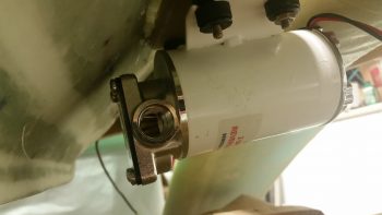
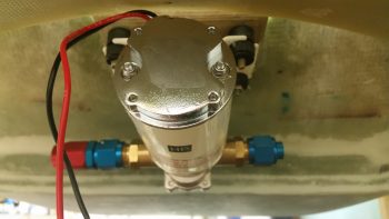
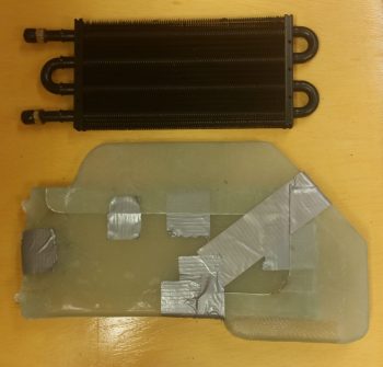
Today I started out by pulling all the tape off of the oil heat pump and checked the clearances both front and aft. The clearances thankfully looked good. As a side note, with the rubber vibration pads, I can tweak the clearance biased either forward or aft a bit just by the amount of torque I place on each mounting bolt.
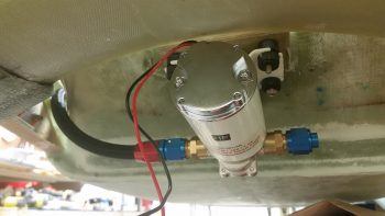
I then placed the oil pump fittings back in place, but this time I went ahead and put the AN hose fitting that will go on the end of the oil feed line that heads towards the heat exchanger.
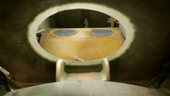
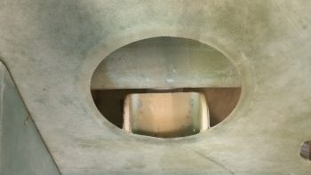
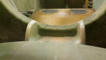
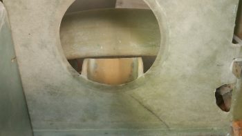
Here’s a shot of the cured and cleaned up oil heat pump mounting bracket.
And another shot.
I then prepregged the next and final round of glass for the oil heat pump mounting bracket installation. I laid up 2-plies of UNI over the edge of each foam upright support tab (after adding micro slurry to the foam and a bit of flox as a transition at the front edge with the seat glass), and then a 2-ply BID tape along the bottom side intersection of the bracket and the back seat (see below).
Here’s the final installed oil heat pump mounting bracket.
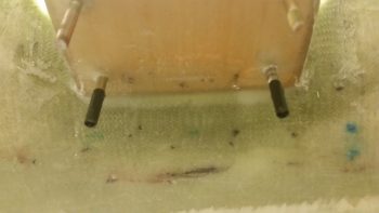
In addition to the 2-ply BID tape, I also laid up a 2″ x 2″ 3-ply BID tape in the center area of the bottom side bracket to GIB seat back for a total of 5 plies of BID right in the middle area of the bracket. I couldn’t lay up a more than just the edge on the outer 1″ of each side of the bracket since the bolt studs are in the way (the ones with the black tape in the pic below).
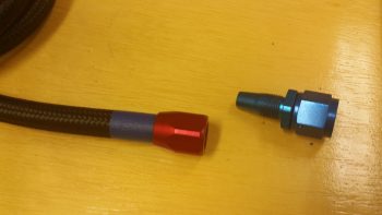
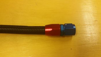
I then got to work building the oil pump to heat exchanger hose, via the 1/2″ to 3/8″ reducer… which this hose will actually attach to. I slid the outer housing of the AN-8 fitting into place until it bottomed out (red piece). The blue tape behind the outer housing was to let me know if the blue fitting piece was pulling the outer housing off the hose more than it should.
I then carefully threaded the blue fitting piece into the red outer housing piece to hand tight at first, then I used a couple of crescent wrenches for the final tightening. Not shown here is the blue tape I wrapped around each component to protect them from getting marred.
I then installed the hose onto the lower reducer fitting in the front left wall bulkhead of the sump tank. I only tightened the fitting hand tight to get a decent idea of the hose length I needed.
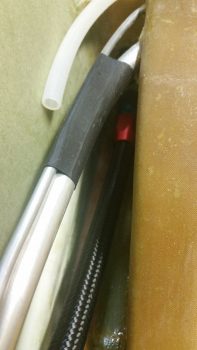
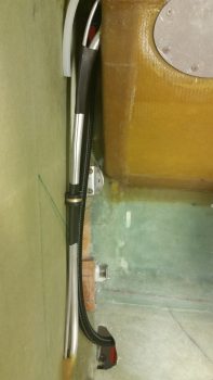
I then ran the house into the hell hole through the lowest hole in the GIB seat back. There I cut the hose to length and followed the same process as before to install the opposite end hose fitting for connecting to the oil heat pump.
I then took a bit of time working on the heat exchanger ducts. I trimmed them up a bit at the corner where they intersect and once they were able to play nicely together, I then taped it all up.
I then spent a good 45 minutes figuring out the exact location that the heat exchanger will get installed in the GIB area in the fuselage. I was remiss to take any pics, but I was able to mark up the existing ductwork (that I have yet to permanently install) and the fuselage floor to know where the heat exchanger will get remounted.
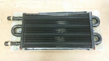
Most importantly, for today, I was able to determine how the heat exchanger will get mounted inside its cover, and in turn, how the whole unit will get mounted onto (and atop) the current ductwork.
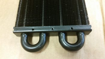
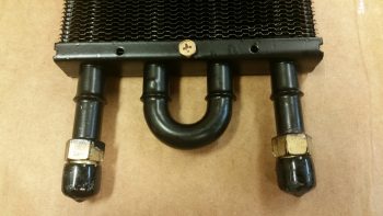
I was originally thinking I would use spacers, but since the locations I chose for the spacers were about 0.5″ from the center holes on the heat exchanger’s side frames, I chose to simply drill those out for a #10 mounting bolt.
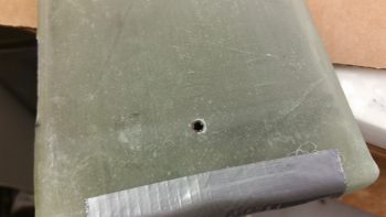
So I drilled out the center mounting hole on the forward end of the exchanger in short order.
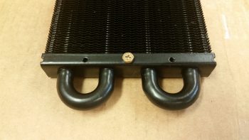
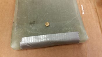
And test fitted a bolt.
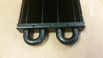
Then I did the same sequence on the aft end of the heat exchanger.
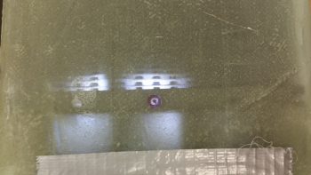
I then remounted the cover onto the heat exchanger, taped up the sides to ensure the heater exchanger was secure, I then shown a light up through one of the holes I had just drilled out in the metal side frame of the heat exchanger and marked it.
I then drilled a hole through both sides off the heat exchanger cover using the hole in the heat exchanger side frame as a guide.
Again, I then test fitted a bolt to ensure the hole was good.
I then did the same sequence on the other end and ended up with another hole going all the way through the heat exchanger and cover.
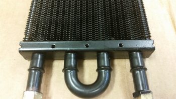
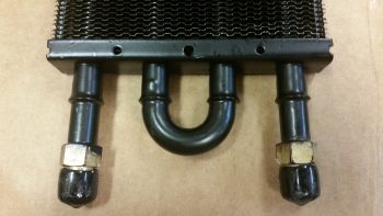
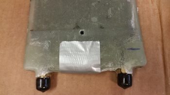
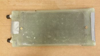
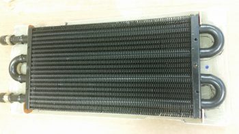
Here’s the heat exchanger with the mounting bolts (test ones) in place.
I then cut out some mini air dams from 1/16″ (0.063″) phenolic to keep the air out of the end “caps” of the heat exchanger cover and flowing only through the finned middle area.
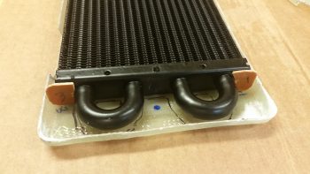
The cover extending over the “U” shaped tubes on each end was glassed that way to make glassing the cover over the heat exchanger much easier. On the front side (shown below) it also created a straight wall to use as one of the interior duct walls for the exit duct of the heat exchanger. Finally, it simplifies the heat exchanger lines and in my opinion makes it look better. Still, there’s no need for the air to get “lost” in those end “cap” areas so I’m keeping the air path focused so that it will run only through the fins, which are kept warm by the hot oil running through the pipes.
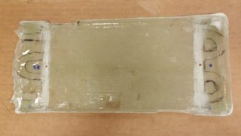
[As a side note, you can see the blue dot close to the hole I drilled in the frame of the heat exchanger. That blue dot was where I had planned on putting a spacer for mounting but obviously decided against it.]
This pic is a little bit washed out, but you can make out the mini air dams at each corner of the heat exchanger.
I then prepped the outboard wall of the heat exchanger cover by sanding the strips that would mate up to the frames on each side of the finned core.
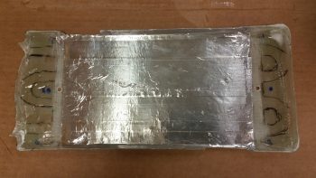
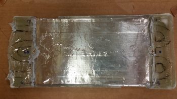
I then cut strips of foil tape and placed them on the inside of the heat exchanger to keep the heat as concentrated in that center area as possible as the air flows through it.
I then did one last test fit to ensure all my parts were good and aligned for what was next…
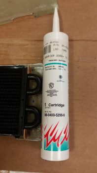
. . . hi-temp RTV.
I ran beads of the hi-temp RTV along the areas I sanded that would mate up with the frame of the heat exchanger. I also put a small bit around the contoured openings for the fitting posts.
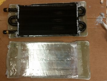
Then, using installed bolts through the mounting holes as guides, I placed the heat exchanger in place onto the beads of hi-temp RTV. I added a good dab of hi-temp RTV at each outside corner of the heat exchanger and set the mini air dams in place, and then ran a bead along the edges of each dam to hold it in place.
I then RTV’d the top of the heat exchanger edge frame, a thin bead along the top of each phenolic mini air dam, and again a small bit around the contoured openings for the fitting posts on the opposite side.
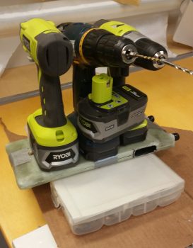
I then set the other side of the heat exchanger cover into place to entomb the heat exchanger once more. I then taped the 2 halves of the cover tightly on each of the 4 sides of the heat exchanger. I then placed the entire unit on a plastic box, added a bunch of drills and heavy batteries to weight it all down in place, and then ran to the store to buy a few groceries I needed!
Upon my return, I had a quick dinner before heading back down to the shop. In all, I let the hi-temp RTV cure a little over an hour total as I also cut the BID for the prepreg setups in prep for the initial glassing of the 2 cover halves back together over & around the heat exchanger.
I used only 1 ply of BID in prepreg setups, all 1″ wide. Since there are some minor gaps that are understandably much wider if no pressure is placed holding the two sides together, I decided to make this a 2, possibly 3, step process (the extra one may be needed for the corners).
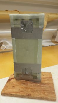
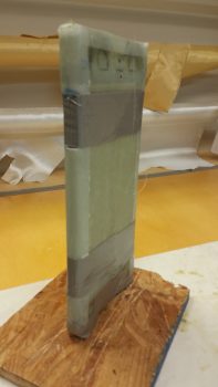
I taped a tight band of duct tape around each duct opening which worked well to keep the forward end (top in pics below) and middle sections tightly together. I did need to use another bit of tape on the corners to close the gap at the bottom side in the pics below (which is the aft side of the heat exchanger).
I then laid up all the glass strips and peel plied them.
Tomorrow I’ll clean up the layups I did tonight and then prep another round of layups to finish closing out the seams in the heat exchanger cover and make it all one unit (It will be a finished unit when the upper & lower ducts are floxed into their respective places on the heat exchanger… as was shown mocked up earlier in this post). I should also get an order I placed with Summit Racing so I’ll have more fittings on hand to continue working on the oil heat lines install.
