
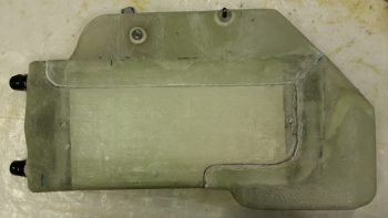
I started out today by cleaning up the inboard face of the heat exchanger by sanding the edges of the added upper & lower ducts where they overlap onto the main assembly.
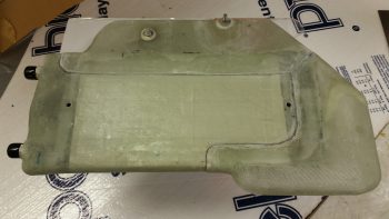
I then cleaned up & prepped the heat exchanger for glass, or actually for 1 ply of carbon fiber.
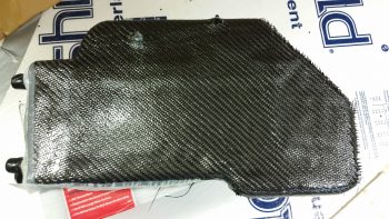
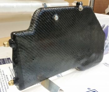
Here’s the ply of carbon fiber after I laid it up and peel plied the edges a bit to ensure it stayed in place. I didn’t go with the traditional super sexy carbon fiber look, since the reason I’m adding the carbon is I believe that with this heat exchanger being inboard of the ducts, it will get rubbed on with legs, knees, small marsupials, etc. over the years. If it was painted, as I’ve seen with many a canard, over time the paint would simply rub off. I wanted something that would not only be a good contrast with the gray granite paint that I’m using for the cabin, but that would be hardy enough that it would withstand getting rubbed on over the years without discoloration or deterioration of the surface.
I used fast hardener so a few hours later I trimmed the carbon fiber and got the heat exchanger pretty much back to the way it was before, just with a ply of carbon fiber on the face of it.
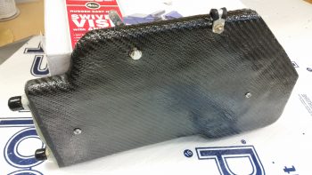
I wasn’t sure what I was going to do with the aft end, I just knew I didn’t want to attempt making my layup infinitely more difficult by trying to put carbon fiber here and wrap it around. Admittedly, my original plan was to get much closer to the edge but the carbon fiber apparently had other thoughts on the matter.
With so much stuff to get done on this plane, I punted and went with the 80% solution to get this thing in the done column, and simply painted the aft end . . . In the grand scheme of things I don’t think anyone will really notice that the aft “face” is painted black.
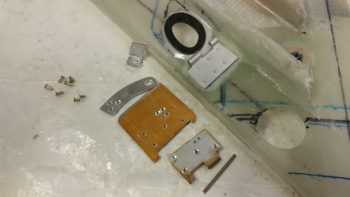
I then got to work on the fresh air/heating air routing valve. Below is the valve assembly in its component parts, ready for assembly.
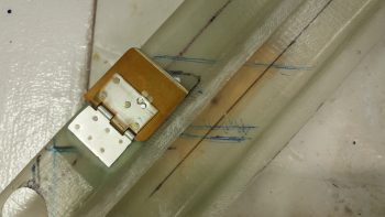
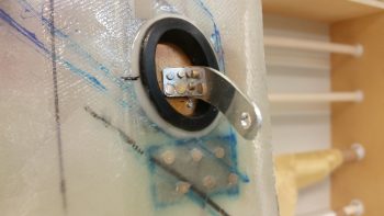
And here’s after I riveted it all together . . . the second time!! You see, the valve hinge had to go in first before I riveted all the main pieces together. So of course I went to Tahiti for a few minutes in my mind while I riveted the first couple of rivets to get it all together. My fault, but what a royal PITA to drill those rivets out. Plus, it widened the holes a bit so I used a bit longer rivets and merely mashed harder!
Ok, so she ain’t perfect, but it looks like this dog will hunt. The one thing I’m not overly happy with is the height of my valve, since it’s taking up valuable space in my duct and reducing the duct’s cross section for airflow by almost 0.5″.
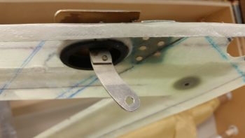
Here’s a shot to see where this valve is in relation to everything else.
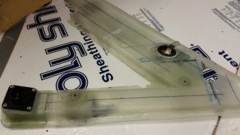
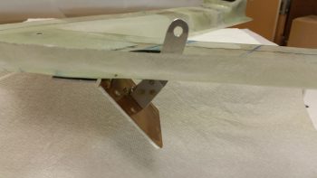
And here’s a few shots of the valve and the attached control arm.
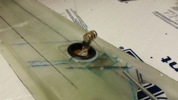
I then added a cable mount bolt and a cable to test out the function of the valve. It’s simple and I don’t think there should be any issues (besides having to trim down the upper edge of the valve since it’s just a hair wide.)
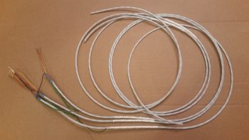
With my ductwork tasks done for the evening, I focused on getting the cable runs to the GIB headset jack squared away, primarily at the Dynon Intercom harness connector.
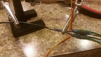
After doing over an hour’s worth of research and brushing back up on the intercom wiring, I then cut the wires to length, stripped the wires and then added shield grounding pigtails by using ground solder sleeves.
The pilot and GIB Mic/PTT wires share a common ground at Pin 2, so I went ahead and did a solder wire splice to add a small length of 20 AWG wire to the 2 shielded wire ground wires. BTW, I used the Bob Nuckolls’ technique for solder splicing 2 wires together.
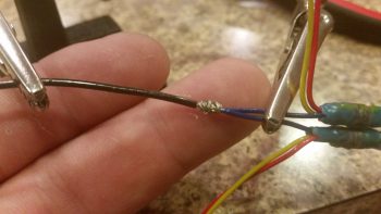
Here’s my soldered wire splice.
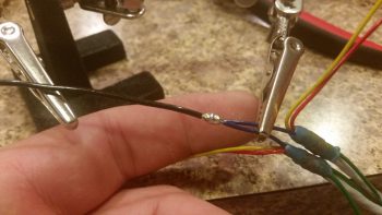
I then added a piece of shrink wrap over the soldered joint.
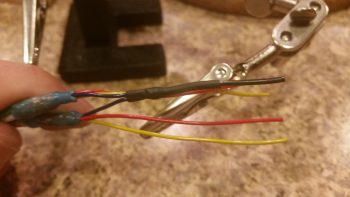
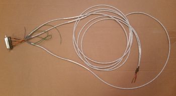
Here’s a shot of my Dynon Intercom wiring harness . . . so far! You can see that I labeled the main cable insulation and terminated the individual wires with the included D-Sub sockets.
Wrapping up the evening, I terminated the sockets into the Dynon Intercom 25-pin D-Sub connector. I also stripped and heat shrank the GIB headset jack ends (the sides in the left GIB armrest) of the cables in preparation for installation.
Tomorrow I’ll continue to work on knocking out all this extraneous build stuff so I can get on to the nose, canopy and strakes.