
Today I started off by heading out to my local hardware store to buy another clevis pin to be converted into my heat restrictor butterfly rod (round 2!) and some other miscellaneous hardware.
Last night I already bought another 4-40 tap set to replace the one I broke. I also looked for the same style clevis pin that I am converting for the butterfly valve rod, but none of them at Lowe’s or Home Depot, which were the only stores open, would work.
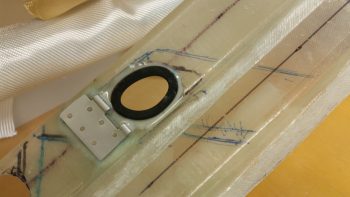
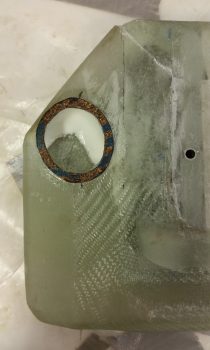
Upon returning home, I then floxed into place the rubber grommet that I configured to go in the hole between the main duct outlet into the heat exchanger’s upper duct (heating air inlet).
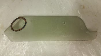
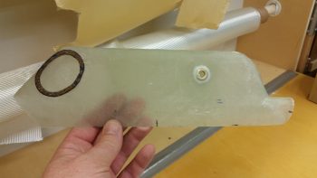
Here’s the backside of that same grommet. This is the surface of the grommet that will actually interface with the gasket that I place around the matching hole in the heat exchanger’s upper/inlet duct (see below).
I had pondered a while last night and this morning on how to fill in the minor gaps between the heat exchanger duct entry & exit holes and the associated holes in the main duct. I mounted the heat exchanger on its ductwork mounts and assessed the widths of grommets and/or gaskets (which I stumbled across during my pondering) that would be required.
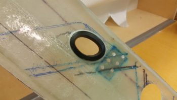
I decided on using gaskets to mate up with the grommets I had just floxed into place. [Actually, I cut out this gasket below for the heat exchanger upper duct and floxed it in place at the same time as the grommet above.]
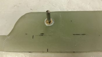
I also went ahead and floxed an AN960-416 1/4″ ID washer in place to use as a reinforcement sleeve for the heat restrictor butterfly valve.
A bit later I floxed on 1.5 gasket rings on the outlet hole on the heat exchanger’s lower duct. I floxed in place one entire gasket ring first, then a half of one shaped basically in a backwards “C” in relation to the pic below.
When I floxed in the gaskets above, I also floxed in the 1/4″ washer on the other side of the heat exchanger’s upper/inlet duct.
The vast majority of the day was spent on constructing the heat exchanger’s upper duct heat restrictor butterfly valve. After snapping my 4-40 tap off in modified clevis pin #1 (which was heat restrictor valve rod #2), I vowed to go super slow and clear the tap at every step this go-around. Well, I got half way through the 2nd hole and wouldn’t you know it: my new 4-40 tap snapped in half! Oh yeah, and this time I was fortunate enough to impale myself on the top of my thumb! Ugh!
Well, after about 15 minutes I was finally able (and fortunate enough!) to remove the snapped off tap piece. I then very carefully was able to use the two broken tap pieces to thread just enough of the remaining hole to mount a screw into it.
Later on, in the same hole –after using countersunk screws all day and well into the evening– as soon as I switched to my new standard stainless steel phillips head screws, the head snapped off immediately as I was just finalizing threading it into place. Ugh!
After another 30-40 minutes of drilling out the snapped off screw, I was again thankful that the slightly undersized drill bit that I used didn’t wipe out my threads in that hole. Going back to my CS screws seemed to do the trick and was definitely the safe option at this point.
Instead of taking a myriad of pics (which I failed to do anyway amidst all the mayhem!), I decided that I could better explain what I was doing with a video… so here you go:
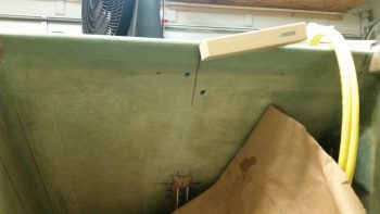
I thought I would also knock out a quick side task and mount the GIB RAM air mount on the aft upper center of the pilot’s seat. Now, I already have one that I mounted on the aft side of the pilot’s headrest, but I need to assess that one further since it may very will get moved or removed altogether depending on how well it plays with the canopy’s reinforcement crossbar.
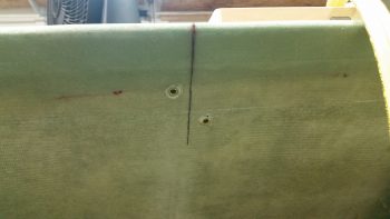
Since I don’t have any extra of my preferred CG-style aluminum hard points, I simply used 2 RivNuts diagonally opposed in opposite “corners” and floxed them into the holes I made below (I’m using 4 screw hard points on this mount). Later I’ll add the other 2 screw hard points.
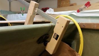
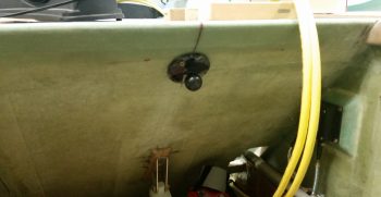
Here’s a shot of the RAM air mount with the RivNut hard points mounted and floxed into place. As you can see, I used my handy German clamp to keep the RAM air mount in place while the flox cures.
A couple hours later, after the flox had cured, I pulled off the clamp to reveal a nice “half-mounted” GIB RAM mount installed on the back of the pilot’s seat.
I then removed the ball mount and did a quick cleanup on the RivNut hard points. Again, I’ll add 2 more hard points when I have them on hand.
Tomorrow will be a half build day since I’ll be helping my friends that are moving to NC. But I do still intend to get a few things knocked out.