
This past week hasn’t allowed for a lot of major build efforts, and I expect that won’t change until starting on Monday. I have some good friends that are moving out of the area so I’ll be spending a bit more time with them over the next couple of weeks.
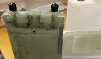
Today I started out by sorting through & figuring out LED lights for the GIB area floor area lights that will be located in the fuel sump tanks’ low fuel warning sensors covers. After figuring out the LEDs, I then updated my cockpit lighting wiring diagram.
I then mocked up the upper & lower heat exchanger ducts after my design, placement, and initial construction of the heat restrictor valve (butterfly style) that resides towards the aft end of the heat exchanger inlet duct.
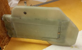
I would have preferred to have the heat restrictor valve located about 1-1/2″ forward, where you may be able to see a location dot. However, since I wanted the valve’s actuator arm on the outboard side of the heat exchanger unit for clearance to keep it from hitting the GIB’s knee or leg when the valve is actuated, I had to place it a bit aft of where I wanted (where it is in the pic below) to allow for valve actuator arm clearance with the underlying (outboard, on the cockpit wall) ductwork.
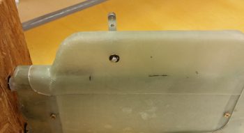
I then laid up 4 more small pieces of BID on the aft side of the heat exchanger to finalize the sealing up of the heat exchanger cover. In addition, I added a 1-ply BID “patch” on each side of the heat exchanger upper inlet duct around the heat restrictor valve mounting holes (seen on the right side in the pic below).
Tomorrow will be another light to non-build day. Again, however, I plan to be back at it hot ‘n heavy on Monday.