
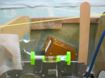
I started off today by taking a pic of the pitch level of the mounted Triparagon. As you can see, the addition of the last 3 nutplate mounting hard points tilted the Triparagon ever so slightly forward. Nothing that can’t be reworked or overcome during the installation of the top “shelf,” but it is something for me to take note of to ensure I get 0° level.
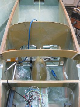
Here’s a shot from the top to show the mounted Triparagon in comparison to the CL. Again, you can see that the Triparagon is very closely aligned, so not bad.
I cleaned up the left side layups on the Triparagon nutplate mounting tabs. In the pic below you can see that the top F28 Triparagon mounting tab still needs to be cleaned up.
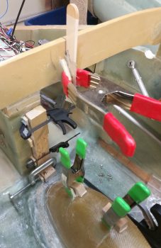
I then laid up 2-ply BID layups on the RIGHT side of the Triparagon nutplate mounting tabs. I then clamped these right side layups so that the glass would cure as flat & tight as possible to allow the Triparagon to mount back into place close to its original installed position.
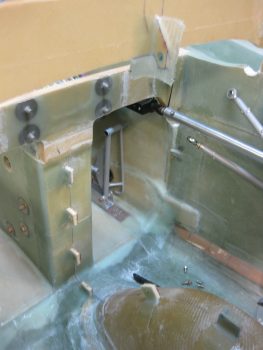
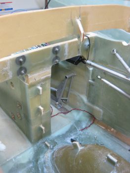
While the right side Triparagon mounting tabs’ glass cured, I took a few minutes to re-drill the GIB seatbelt crosspiece screw holes, since I had inserted G10 hard points to buttress the square cross tube.
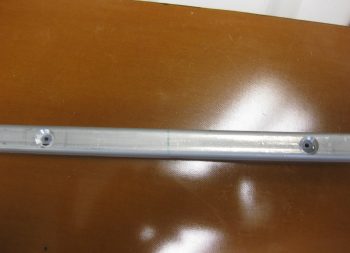
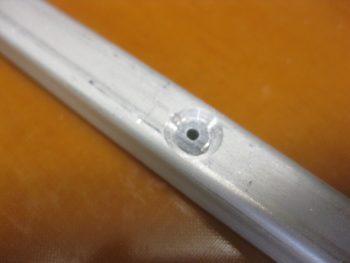
Here’s a closeup shot of the initial drilling of the G10 hard point in the GIB seatbelt crosspiece screw hole.
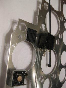
I then started back working on the actual Triparagon by remounting the electrical components to it. I also drilled a couple holes to allow a zip tie to be used for mounting the Trio autopilot Autotrim relay –along with a patch of velcro.
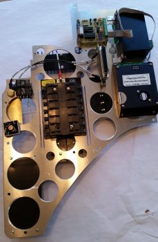
I wired up the G5 avionics ground buss to connect it to the bolt mounting the G4 panel ground buss. Here’s a shot of the left side Triparagon.
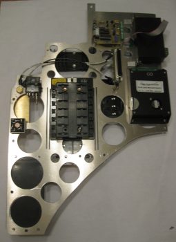
Another shot of the left side Triparagon. You can see below that I also wired the E-bus to the Schottky diode.
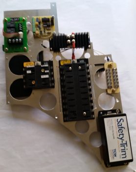
Below is a shot of the electrical components remounted to the right side Triparagon (with a pic hue for some reason).
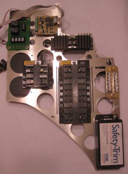
And another shot of the right side Triparagon. Again, note that I wired the E-Bus feed by adding a wire between the Main Buss terminal to the Schottky diode (sorry for the slightly blurry pic).
A few hours later I removed the clamped blocks off the Triparagon nutplate mounting points and cleaned up the 2-ply BID layups.
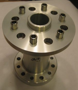
I also wanted to add a shot of my prop extension back from Sam at Saber Manufacturing. As you can see, he added in 3/8″ bolt holes and bushings for the Silver Bullet prop on the prop side, and he also added 7/16″ bolt holes in between the 1/2″ holes for mounting the extension to the engine prop flange.
From here on out my main focus will be on wheel pants until I get those nearly fully installed.