
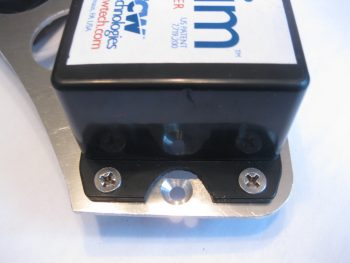
I started out today by undertaking the task of removing part of the TCW Safety Trim box’s lower mounting bracket, which was covering and in the way of the bottom Triparagon mounting screw hole.
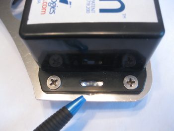
So I removed a half moon notch of the mounting bracket and uncovered the bottom Triparagon mounting screw hole.
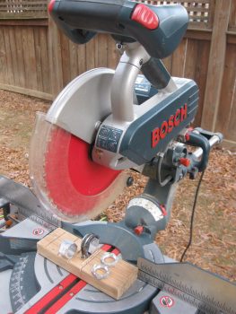
In other news, I fried my heat gun last night. So after a trip to Harbor Freight to pick up a nice cheap replacement heat gun, the weather was nice so I got to work outside to complete quite a number of cuts that were required with aluminum pieces & stock.
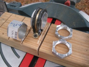
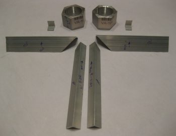
The first task was something that I’ve needed to do for a while now. Since I finally got the correct sized Adel clamp in my latest ACS order, I was able to clamp down the Matco wheel axle nuts (from VANs Aircraft) that are used to mount the outboard sides of the wheel pants. Since I won’t be using them as per their original design, I need to shorten them to 1″ in width from outboard to inboard. Specifically, I won’t be using the cotter pin holes, so those are going away.
Just as I did my LWA9s & CNLs, I clamped the axle nut extensions into the Adel clamp & secured it with a screw. I then took my time to ensure that the axle nut was 90° to the mounting board.
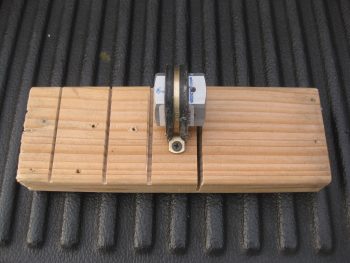
I then used my saw to slowly cut the axle nut down to 1″ width.
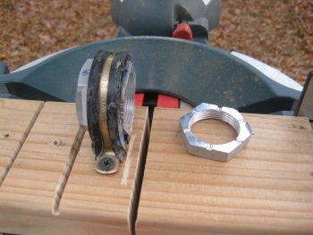
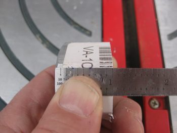
The actual width came out to be more like 1.05″, which works fine.
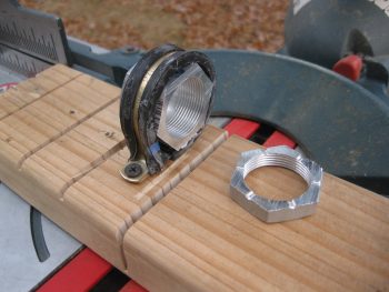
Here’s a shot showing both axle nut extensions cut to 1″ in width.
And a closer view . . .
I then spent a good bit of time cutting the angled aluminum extrusions for the Triparagon upper cross shelf. The 2 extrusions in the foreground of the pic below are for actually attaching the Triparagon’s top horizontal cross shelf to the vertical plate. The larger angled pieces shown left-to-right are primarily additions to the front of the cross shelf that will be used for both mounting smaller components, such as airspeed switches and the warning horn, and also for the diagonal supports for the Triparagon top cross shelf.
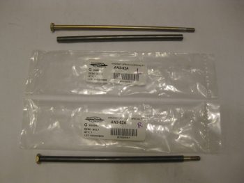
Since I was in a cutting mood, I also cut the 4130 steel tubes to length that will be used as bolt inserts in the longeron doublers for mounting the 2 newly acquired AN3-62A bolts. These assemblies will hold the canard in place at the upper mounting tabs in lieu of the plan style pins. The bolts look a bit curved due to the camera angle, but they are in fact straight!
As I mentioned in the Project Update, I’m working on the Triparagon right now and my main goal in finishing it at this point of the build is really threefold:
- Ensure the Triparagon concept works & can be incorporated with a minimal (and acceptable) weight penalty.
- Install the Triparagon and ensure it fits while I have access to the nose area.
- Wire all the resident components on the Triparagon. This is primarily wiring cross-connects for ONLY those circuits on the Triparagon. All other components will get wired as they are installed.
I should state that part of my fit & finish testing for the Triparagon includes the B&C Voltage Regulator, which is not actually mounted on the Triparagon, but immediately forward of it on the aft upper side of F22. So I also wired all the connections from the Voltage Regulator to Triparagon components.
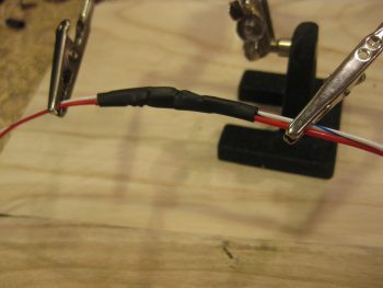
The long pole in the tent for the Voltage Regulator wiring was the wires coming off of pins 3 & 5, since they both connect to main buss power and pin 5 drives the warning signal to the AG6 warning annunciator. The warning circuit required a 1K ohm resistor which I soldered into place.
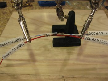
Here you can see the 1K ohm resistor soldered into place, and the heat shrink in place on the respective wires to help build wire thickness for physical joint strength when the final piece of heat shrink is put in place.
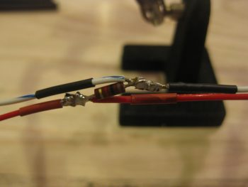
The final heat shrink tubing in place over the resistor that’s tied in between the voltage regulator’s pin 3 & 5 wires.
Tomorrow I’ll continue to finalize the Triparagon components’ wiring cross-connects before moving onto the wheel pants install.