No more electrical stuff for me… back to the GIB area! Ok, except this one sideline task. HA!
Today I started by finishing up annotating the J3 PQD connector color codes, which of course meant digging in the GRT Mini-X manual and also seeing what the wire colors were that I physically had on hand. Since I had the Mini-X wiring harness (15-pin D-Sub) in my hand, I decided to go ahead and knock out the wire harness connector for my Mini-X.
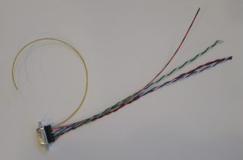
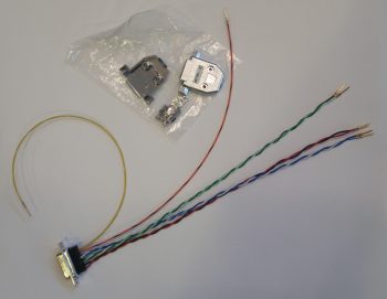
First, I had to pull a few wires for connections that I won’t be using. These few specific wires came installed on the GRT-provided 15-pin D-Sub connector/harness. I measured the required wire lengths between the back of the Mini-X and the J3 PQD connector on the Triparagon. I added a couple of inches for ‘insurance’ purposes and another half inch to account for the multiples pairs that would be twisted together, then ended up cutting all the wires down to 10.5″ long. I then crimped some D-Sub sockets onto 3 wires for the magnetometer (since it’s optional) and terminated them into the Mini-X D-Sub connector. I then twisted the appropriate wire pairs together using a small portable drill.
I then terminated the ends of the wires with D-Sub pins on the opposite end from the Mini-X connector and performed a continuity check on each wire… all good.
Then, on the Mini-X side of the harness I installed the D-Sub backshell.
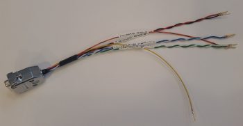
Having also just received some more correct-sized wire labels, I then labeled the 2 individual wires and the 3 wire pairs.
For the panel component labels that run ONLY between the panel components themselves, or the panel components and the PQD connectors, I’m using a bit more simplified wiring label scheme than the one I use for the rest of the plane: essentially providing just a pin number, the wire function such as “power” or “DU link” and an opposite pin number, all separated by dashes. Obviously, on the panel I’m looking at the wire runs from the back of the given device and seeing its termination point just a scant few inches away… all the info is there for me to see straightway, except the pin #’s and wire functions. So, for example, the lone magnetometer signal wire label goes like this:
10-MAG SIG-9
Pin 10 on the Mini-X EFIS D-Sub connector, the truncated description as to the function of the wire, and Pin 9 on the J3B PQD D-Sub connector. Short and sweet. If a twisted pair is getting labeled, I simply add both pins on each side separated by a “/” (aka 11/12). I’m still sticking with the more robust label scheme throughout the rest of the plane which allows me to determine where the wire is coming & going, what devices it goes to (points A & B) and what pins it connects to at each end (typically power, ground or data signal).
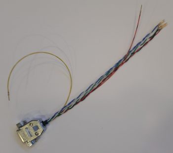
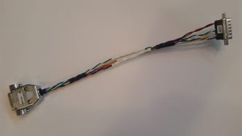
Here’s a shot of the Mini-X wiring harness, minus the D-Sub 15 backshell (which is on order) for the J3B side.
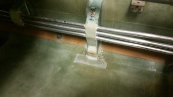
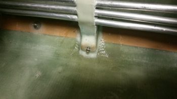
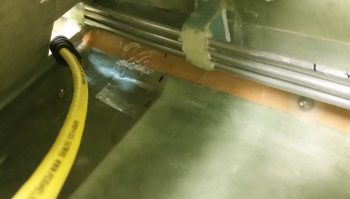
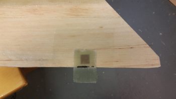
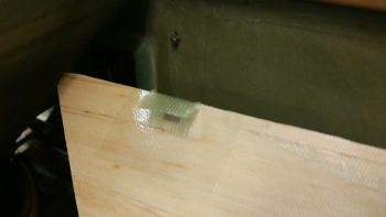
I then set my sights on finalizing the GIB right side kick plate mounting. I started by stuffing some plastic saran wrap into the aft lower hardpoint screw hole, and then laid up a ply of BID over it.
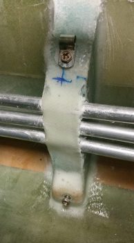
A few hours later it was really close to being cured, so I hand drilled the hole through the glass in the front to remove the plastic. I then cleaned up around the hard point screw hole and test fitted the screw.
Here’s another wider angle shot of above.
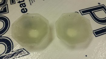
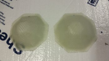
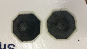
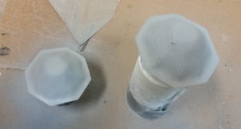
I then spent a bit of time sanding down and cleaning the fuel sump low fuel sensor covers.
Here’s the exterior side of these things . . . After sanding, I then gave them a good Simple Green wash and dried them off.
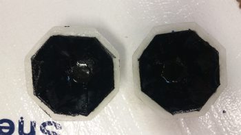
I then taped up the interior edge of both sensor covers and then shot them with a couple quick, light layers of black paint. I would have preferred to use matt paint, but I only had gloss on hand so they’re a bit fancier than I had intended.
I then prepped both the outboard side fuselage area and of the interior wall of the kick plate with clear packing tape to keep the composite bracket from gumming anything up.
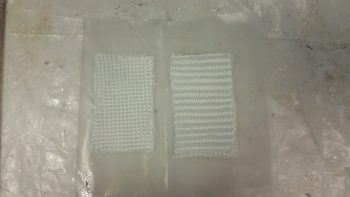
I then set up 2 prepregged 3-ply BID layups.
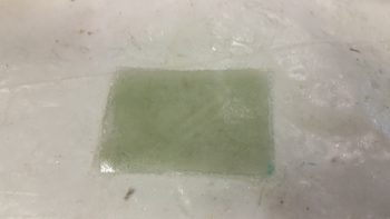
I then wet out the prepregs and combined the 2 stacks of 3 plies to make up a 6-ply forward kick plate mounting bracket.
I then laid up the 6-ply bracket layup half way onto the forward kick plate mounting hardpoint.
I then folded it back on itself so that it was almost touching. My goal here was that when the kick plate was mounted, gravity would simply pull the glass down onto the protective tape on the floor, creating the exact correctly shaped bracket blank –since the floor at the corner here is 45°– after it cures.
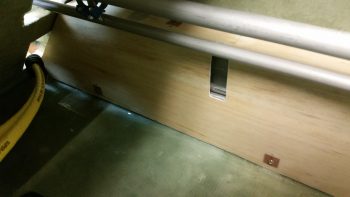
Here’s a shot of the entire kick plate, with the 6-ply mounting bracket glass formed on the inside. I was able to get just a peak of it through the holes in the front seat bulkhead and from what I could ascertain, my “shot in the dark” layup looks ok.
As the kick plate bracket glass cured, I then took a quick opportunity to apply a couple of coats of gray primer onto both thigh support fuel sump low fuel sensor covers. Since I’ll have a pair of LEDs poking out the bottom of each of these covers, I wanted to get them painted so as to not have to worry as much about taping off those LEDs, which again will be on the bottom side, when I paint the rest of the back seat area.
Tomorrow I’ll continue working on all things GIB!
