
I started off today spending about 45 min updating my cockpit lighting electrical diagram and printing it out.
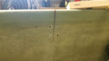
I then removed the GIB RAM mount to inspect the mounting holes and do an initial cleanup. I still need to fill some areas around the inserts with some more flox/micro, but they all look good.
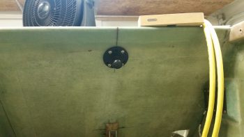
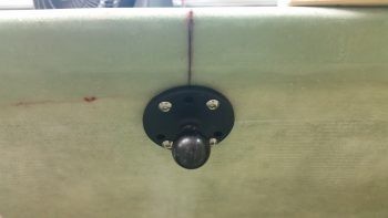
I then remounted the RAM mount to see how it fit and how it looks. I’ll say that I’m very happy with this install.
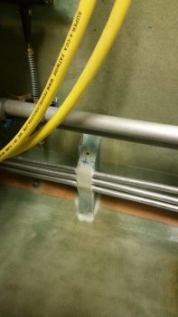
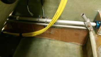
I also checked out my other hardpoint insert from last night. This hardpoint is for the small wire bundle [meaning a bundle of small wires, not necessarily a small bundle . . . ] that will be routed just under the top edge of the kick plate that will run along the right side. I was going to put an Adel clamp here, but with the slant of the top of the fuel line mount, it would just be too bulky. So instead I mounted a metal tab that I’ll then be able to secure the wire bundle to.
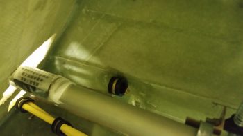
Here’s a shot a bit later after the 2 plies of BID that I laid up over the forward small wire bundle Clickbond cured. I then set an Adel in place to check out the fit. And yes, I realize that I still need to get in there and clean up the forward fuel line mount since it’s looking a bit messy.
Here’s another shot of the forward small wire bundle Adel clamp. This too will be hidden from view when the kick plate is installed.
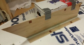
I then tweaked the scrap cardboard template I made up last night to determine the dimensions of the GIB right sidewall kick plate. As you can see, it runs from the aft edge of the pilot’s seat to the front edge of the thigh support fuel sump front wall . . . specifically the right side bulkhead.
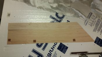
After I got the kick plate dimensions squared away, I then cut up a couple of pieces of 1/16″ thick Balsa wood that I had on hand just for this purpose. I determined where my lower mounting hard points would be, then cut 0.7″ x 0.7″ phenolic pieces and inserted them into the Balsa kick plate to reinforce the areas on the kick plate that will get screwed in place to the sidewall.
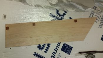
Here’s a shot of the other side, but with all the phenolic hard points and the two strips of Balsa wood micro’d in place.
I then laid up 1 ply of scrap UNI on the interior side of the kick plate.
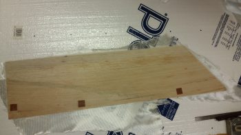
I actually had a lot more planned to knock out today, but late in the afternoon my friends that are moving to North Carolina called and requested my assistance, so I was out most of the evening. I did manage to trim up the layup on the interior kick plate when I returned many hours later.
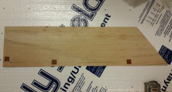
I then cut more Balsa strips for the top, inserted 2 phenolic hard points and prepregged a couple of 1-ply BID layups. I then laid up 1 ply of BID on each end, overlapping in the center. This overlap helps reinforce the center a bit since I used 2 pieces of Balsa for the top, which precluded me from having to use an entire new strip of Balsa wood (remember: I’m cheap!).
I of course used a micro fillet and micro’d the phenolic hard points in place before glassing the interior of the top.
The top is 1.6″ wide, so I used 2.5″ for my width on the first ply of BID to glass both the internal top surface, but also overlap onto the kick plate side piece 0.9″. In addition, I laid up an extra BID tape in the corner that was 1.5″ wide, so it overlapped about 3/4″ onto the top and side pieces of the kick plate.
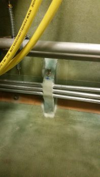
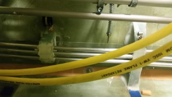
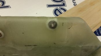
In addition to my kick plate shenanigans, I also laid up a ply of BID over the Clickbond I floxed into place last night onto the heat exchanger’s upper duct, to be used for an Adel clamp to secure the heat restrictor valve cable in place. I peel plied that layup, and below is a shot after it cured and I pulled the peel ply.
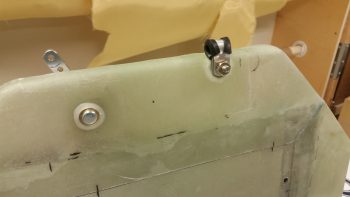
I then attached an Adel clamp to ensure the fit & finish was right… so far, so good!
Tomorrow is a planned day to help my friends moving to NC, so I don’t think I’ll get any building done at all.