
First off, I’d like to convey my latest task sequence plan for the build. My immediate goal is to finish up the GIB area components since those will be the hardest to work after the strakes are installed. I’m giving myself up until 1 August to finish up these GIB seat area, pilot seat area, and nose component installs and then move on to building and glassing the top of the nose. Then I’ll move onto constructing the canopy.
As for today, I started off by prepping the left GIB armrest forward mounting bracket for getting floxed to the left fuselage sidewall.
After mounting the forward mounting bracket to the left GIB armrest with its attach bolt, I then mixed up some flox and slathered it onto the outboard side of the mounting bracket.
I then mounted the left GIB armrest into place, installing the 4 aft bolts into place to hold the freshly floxed armrest forward mounting bracket firmly against the fuselage sidewall.
I used the same epoxy that I used above to layup a ply of BID to seal the cut angled edge of the heat exchanger lower duct piece. This edge was one that I had to cut to remove the duct piece off to the heat exchanger cover. I then peel plied it.
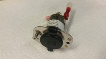
 While the epoxy above cured I digressed a bit to knock out a small task that while not needing accomplished just now, curiosity got the best of me. I drilled and riveted 2 nutplates to the GIB cigarette lighter charger that will be used in mounting it later on.
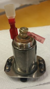
Here’s a shot of the backside of the riveted nutplates.
In addition, I also mounted the two 1/2″ oil heat lines that terminate into the reducers mounted into the left side bulkhead that is an extension of the GIB thigh support fuel sump front wall (no pics). There’s not a lot of space to get in there to mount the oil line fittings, so it took a bit of time to get them installed. I still plan on making a specialized wrench that will better allow me to install & remove these 1/2″ oil lines due to this limited space.
By the time I finished riveting the nutplates onto the GIB charger & installing the oil lines, the layup on the heat exchanger lower duct piece was cured enough that I pulled the peel ply & cleaned it up. I then “mounted” it on the heat exchanger, positioned it in place where it will be mounted in the cockpit, and then drilled a hole through the aft heat exchanger mounting hole into the lower horizontal duct that sits immediately behind (outboard) of the heat exchanger.
I then removed the ductwork and sanded down a 2″ wide swath from the top edge of the lower duct flange to the bottom flange edge, with the mounting hole in the center (1″ mark) of the sanded swath.
Here’s a wider angle shot.
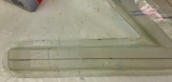
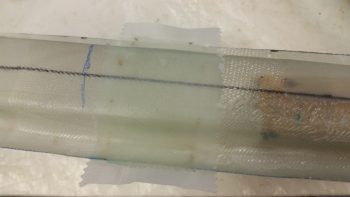
I then laid up a 2″ wide ply of BID from the top edge of the horizontal duct flange to the bottom flange edge for reinforcement when the heat exchanger is mounted. For a little extra strength, I also laid up a second ply of BID 1.5″ wide that terminated on the bottom and top edge of the actual duct (not the flanges). I then peel plied the layup.
I had also cut out a 0.5mm piece of aluminum (from my German stock) to use as a hardpoint for the midpoint attachment of the right side storage pocket to the right GIB armrest. This setup is simply to reinforce the midpoint glass so that it won’t crack under the pressure of the countersunk screw that will be mounted.
I then floxed the aluminum piece in place and covered it with 1 ply of BID using the epoxy that I had made for the layup above. I then peel plied this layup as well.
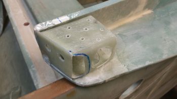
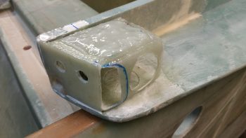
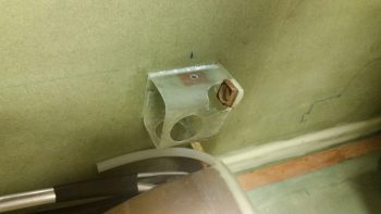
I then removed the left GIB armrest to reveal the forward mounting bracket, which of course also serves as the GIB headset jack plate and PTT button mount. I had just a bit of flox leftover from the previous layups, so I used that to seal the perimeter of the flox on the bracket.
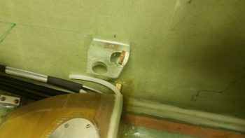
Here are a couple more shots of the left GIB armrest forward mounting bracket floxed in place.
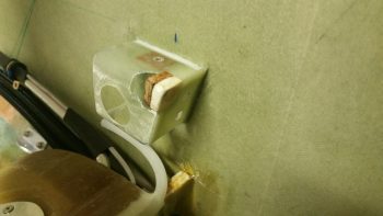
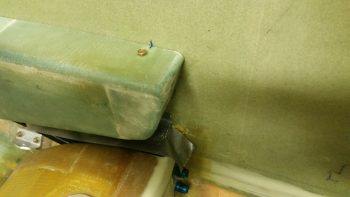
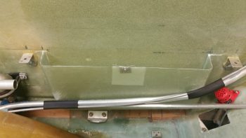
Here’s a pic of not only the left GIB armrest forward mounting bracket floxed in place, but also the two 1/2″ oil heat lines that I mounted earlier.
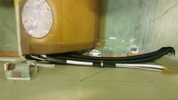
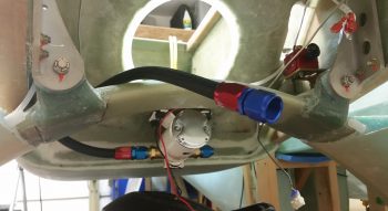
Here’s a shot of the oil feed line that I previously mounted that comes out of the oil pump and to the heat exchanger via the 1/2″ to 3/8″ reducer. In the foreground you can see the oil return line that comes from the heat exchanger back to the engine oil sump. I terminated this oil return line hose with the AN-8 fitting just prior to taking this pic.
My final task of the evening was working on the heat exchanger upper inlet duct’s restrictor (butterfly) valve. I started off by redrilling the valve mounting holes that I had covered up with the reinforcement plies of BID, then inserting the valve plate’s mounting rod into the duct holes and marking the sidewall positions onto the rod.
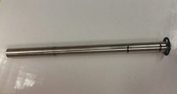
I then Dremeled and filed a flat spot almost 1/16″ (0.060″) deep into the valve plate’s mounting rod specifically to mount the valve plate to.
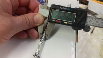
The diameter of the valve rod is 0.240″.
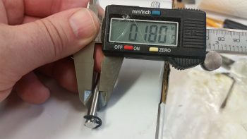
And as you can see, the width of the rod after I cut nearly 1/16″ of it out, is 0.180″. Makes sense eh?
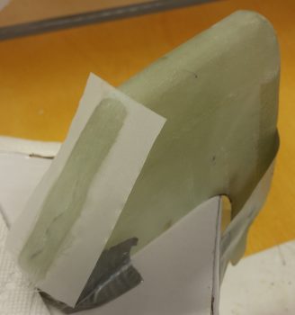
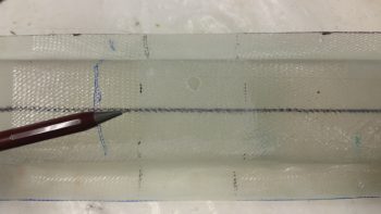
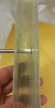
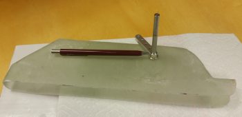
Here is the valve rod installed in the duct with the valve plate mounting flat showing. As you can see, I need to make the flat a little wider so that the edges of the valve plate sit flush with the duct sidewalls.
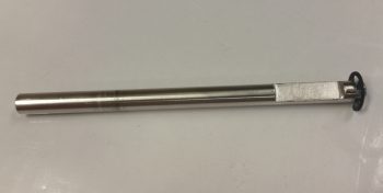
I’ve left the heat restrictor valve rod long for now, but will be cutting it to length in the next day or two after I’ve worked out & finalized all the other working valve dimensions. It will most likely get cut at the spot where the tip of the pencil is pointing to.
The side shown below is the outboard side, so as I mentioned before the valve lever will operate “behind” the heat exchanger and away from any body parts of the delicate GIBs! ha!
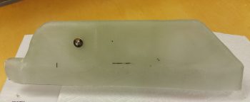
Here’s the inboard side of the heat exchanger, with the restraining E-clip showing on the inboard end of the heat restrictor valve rod.
Tomorrow I will continue to work all the GIB area component installs, including working to finalize all the stuff I worked on today.