
Today I made a hard right turn in regards to my current tasks to get the cockpit component installs squared away now, so I don’t have to do them later after the install sites are buried underneath top nose foam/glass and/or behind the strakes.
I started off today with the intent of just knocking out wiring up one of micro-video cameras with an extension length of wire (a run to get from the camera which will be positioned just forward of the fuel site gage to behind the instrument panel). Why today, you may ask…. well me digress just a bit:
When I tested out the micro-video camera a few months ago I discovered that the image was definitely clear enough to incorporate for viewing not only of the respective left & right fuel site gages, but also a top camera –mounted in the pilot headrest– looking aft at the engine, prop and top cowling [perhaps a view of the GIB’s face too to ensure they’re ok]. I then decided to add a camera to view the bottom of the aircraft from the nose area looking aft, again to verify all is good down below.
With 4 onboard cameras, I needed (read: “wanted”) a way that I could bring all the cameras’ video lines together into one component to feed the HXr’s RCA-to-USB video input feed device. I talked to GRT and they stated that their USB video feed device only accepts one input. Moreover, I wanted my video feed combiner –that feeds the GRT device– to auto cycle through the cameras, showing a video feed for 3-5 seconds on each camera, before moving to the next camera. Lastly, I wanted to be able to cycle quickly to one of the 4 specific cameras to watch its video.
I posted my question on Bob Nuckolls’ AeroElectic Connection forum and besides Bob himself, got tons of interest on creating a RCA IN-to-RCA OUT video feed device that would control & cycle n number of cameras for 3-5 seconds each (user set), and would be simple to control. Bob opened up an official project file on this device and two very electronic tech savvy forum members took on the project based on my requirements. Pretty helpful (and cool) to be sure, but at this point the most pertinent part of this story is the two guys honchoing this project need camera, video feed and system data . . . from me.
Now, since I know from UPS tracking that my GRT USB video feed device will be delivered tomorrow, I decided to prep the micro video camera a bit to see if swapping out the typical bulky RCA cord for shielded 2-conduit aircraft grade wiring would work. However, as is often the case, this is the same wiring that might be required to finish off the Intercom connections . . . ok, long story to state that I felt I should finalize the Intercom wiring –a goal when I started the panel mockup wiring anyway– to figure out how much wiring that I had on hand to use for the micro camera’s video feed test.
So on to the prerequisite intercom wiring, I started off by crimping a D-Sub socket to the end of the Dynon Intercom power wire.
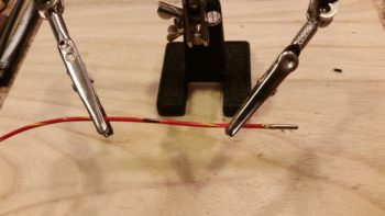
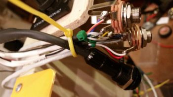
Although I could have done the next step with the wire strippers much easier beforehand, I then used a razor knife to cut away the Tefzel conductor to expose about 1/4″ of bare wire (pic #1 below).
I don’t yet have a Bose noise cancelling headset… yet, but I wanted to go ahead and get the Bose LEMO headset jack wired in with the traditional standard style headset jacks. The Bose LEMO headset jack powers the headset so that you don’t need the bulky battery pack sitting in your lap and in the way [again, not much room in a Long-EZ!). For the Bose LEMO headset power, I then spliced and soldered an inline fuse holder for a 0.25 amp fuse that is required as per the Bose connector install instructions. Of course they don’t make ATC fuses (to my knowledge) that small, so I had to go old skool with a glass fuse.
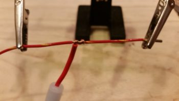
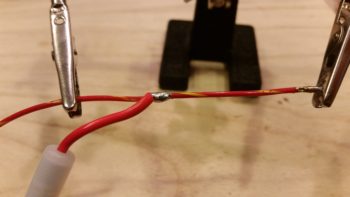
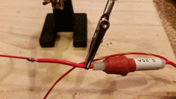
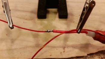
Here’s the final solder splice, connecting the Bose LEMO headset jack input power feed parasitically to the Dynon Intercom’s power wire.
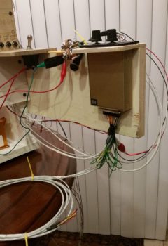
I then spent a few hours, involving 4 batches of printed heat shrink wire labels (around 8 labels per batch) with the majority of those applied, knocking out the wiring connections of on the Dynon Intercom wiring harness D-Sub connector. Since most of these wires are shielded, it took a bit of time finalizing all these wiring cross-connects. In the pic below, the Intercom wiring bundled together on the table are the cables for the GIB headset jacks and the COM2 radio.
Regardless, I’m calling the Dynon Intercom wiring harness complete, with some options open for future connections (i.e. remote music jack for GIB, direct EFIS audio input, etc.).
The last push on knocking out the Intercom wiring was to connect the 2 standard headset jacks (phone & Mic/PTT) and the Bose LEMO headset connector. Besides a power & ground wire, the latter simply ties into the 2 standard headset jacks.
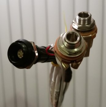
Here’s a bit closer shot of the headset jack wiring. My soldering won’t win any beauty contests, but it’s definitely good enough to work.
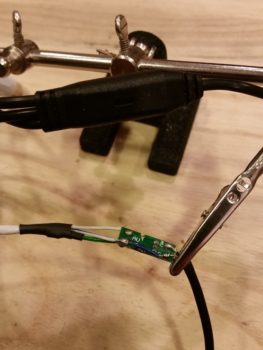
After spending quite a few hours getting the Intercom wired, including power, all the cross connects, and the headset jacks, I finally got to my initial task: wiring up the micro video camera. I had originally removed the plastic shroud –shown intact on the unmodified camera wiring above my science experiment– covering the mini circuit board that feeds the camera. While removing this plastic encasement, I nicked the circuit board and cut the thin foil circuit that connects the exterior video feed to the camera video feed. Thus, when I attached the long aircraft wiring feed to the circuit board, I also had to do a little cross connect wire addition to repair the wayward neanderthal damage I had caused earlier.
When I tested out the extended aircraft wiring connection, the camera was much grainier than the unmodified camera. Ironically, all the trouble I went through to ensure I had enough shielded wiring on hand was probably for naught. My instinct is telling me that the shielded cable that I’m using for ground is inducing too much resistance and that I need to try using just regular wire for the ground lead. Still, I’ll continue to play with it some more to see if I can get the cameras to work using aircraft wiring for the longer leads.
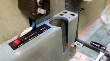
It was getting late and I had yet to make the requisite amount of noise that I usually do in the shop, so I carefully cut out the front top of the left armrest that I had marked the outline of the heating switch panel onto. I then test fit the armrest in place over and around the now permanently installed heating switch panel, with of course then mandated rounds of sanding, fitting, etc.
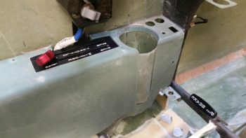
I then mounted the cupholder and test fitted the left armrest in place again. It fits ok, but there is definitely some fine tuning required over the next day or so to get all these components dialed in and playing nicely with each other fit & finish-wise. Still, this gives you a good idea of the configuration on the front half of my left armrest.
Tomorrow I plan on being back in the shop for most of the day, and then fiddling about with the GRT HXr RCA-to-USB video input feed device later in the evening.