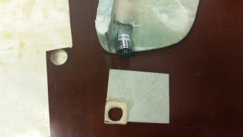
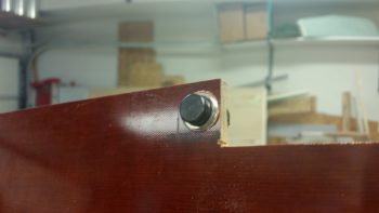
I started out today working on the GIB PTT button configuration & construction of a front plate for both the GIB PTT button and GIB headset jacks, all which will reside on the front of the left GIB armrest. It may be a bit hard to tell, but the greenish blob coming down from the top of the pic below is the front of the left GIB armrest. Top of armrest is to the left, with the PTT button resting in the notch I created for PTT button clearance.
I positioned the PTT button notch where it is to get the PTT button as far up into the inboard corner of the armrest front face for easier “mashing” of the button any time the GIB is going to use it. However, to stay clear of the PTT button being inadvertently pressed or an open mike situation, I’m recessing the button so the top of it is just below the face of the armrest front face. Thus, at the center bottom of the pic is the piece of 1/16″ G10 I cut as the armrest front face cover plate, and in the corner where the PTT button will go, I notched it and shaped a piece of Divinycell foam with a 1/2″ diameter hole for the PTT button to sit in. I 5-min glued the foam piece in place, then when cured I radiused the perimeter edge of the hole.
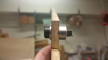
All this is sitting on a piece of 1/4″ phenolic which I drilled a 0.609″ (39/64″) hole into for the actual securing of the PTT button as it’s press fitted into this hole with some Silicone RTV to lock in nice & tight.
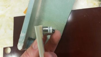
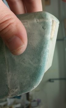
Since the left armrest front tapers aft at the bottom, I tapered the foam PTT button recess housing so that the PTT button would sit parallel with the top of the armrest for clearance on the internal side of the armrest. Here you can see the PTT button set in place where it will get mounted. If you look just forward (left) of the ID label sticker you can see the wider 0.609″ flange that will get press fit mounted into the phenolic. The phenolic piece will of course get floxed to the aft side of the tapered foam recess housing.
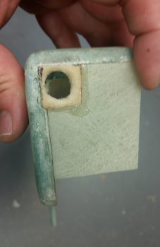
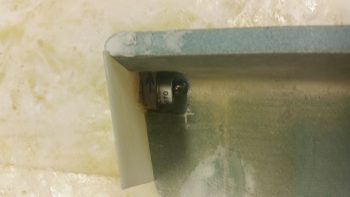
I then tested the fit of the assembled armrest front face piece in the notched corner I created in the armrest. When finished, this front face piece will be an integral part of the sidewall bracket that remains on the fuselage sidewall when the armrest is removed.
I had to do some very light sanding after I drilled the 0.609″ (39/64″) hole for the PTT button to fit, which it did with a reasonable amount of force. Perfect.
Again, the physical mounting of the GIB PTT button will be in this 1/4″ phenolic block piece that itself will get floxed to the aft side of the foam recess housing that is attached to the front face piece.
I then cut out the phenolic block and trimmed it up. I then mocked up the PTT button secured in the phenolic block, set in place where it will attach to the foam button recess housing, all with the front armrest face piece set in place.
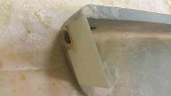
Another shot of the recessed PTT button in the left GIB armrest front face piece.
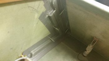
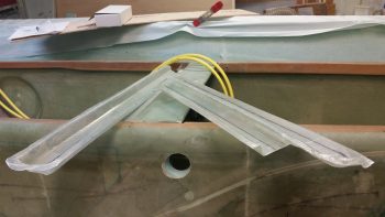
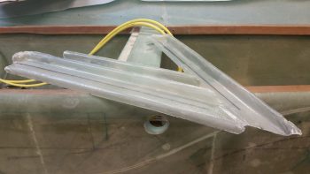
I then started back working on the GIB area heat & fresh air ducts that I laid up last night. My first task was to drill some 3/32″ holes into the flanges and install clecos to ensure I would later have the correct duct alignment when remounting the ducts back in place.
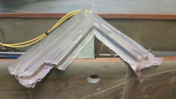
I then removed the clecos and fought for a good 30 minutes to get this ductwork assembly off of the interior fuselage sidewall . . . .
. . . notwithstanding major puncture wounds to my finger and thumb and a fair amount of blood!!! Literally blood, sweat and tears in building this plane!
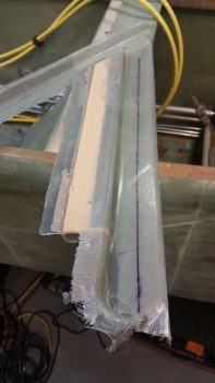
I removed the foam & tape for both the main air feed and the horizontal GIB lower air feed, but the air feed that goes back up top for the GIB high air feed I couldn’t remove without a lot of difficulty unless I trimmed the glass flange that will secure the shared duct wall with the main air feed. This flange is from the main air feed and had I not subsequently glassed the adjoining parallel GIB high air feed duct right next to it, it would have stood on its own as a “normal” duct without being integrated into a 2 channel duct (or 2 separate ducts sharing an internal wall).
Well, I trimmed down all the flanges and was able to remove the foam from the GIB high air feed duct. I didn’t weigh this ductwork assembly but it is super light, as one could imagine with it being just a couple plies of UNI.
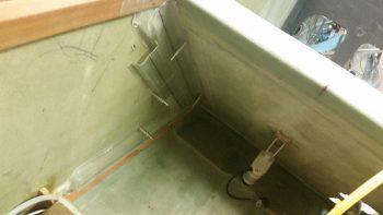
I then clecloed the air ductwork assembly back in place after cleaning up a few spots on the internal fuselage sidewall.
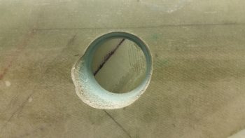
I snapped this shot of the main air feed as seen from the external fuselage side, through the ram air inlet, expansion chamber and transition tube hole.
Starting tomorrow up until mid-week will be light build days, if I get any building done at all, since I have Independence Day celebration activities, out of town visitors and get-togethers, etc.

