
My goal today was to get the engine mounted. Having the engine mounted for a bit will again allow me to figure out firewall component placement, firewall pass-thrus, the engine compartment hose requirements, firewall/engine electrical wiring requirements, upper cowling fitting (specifically for canopy/D-Deck angle), initial baffling requirements, lower cowling fit and air intake (fuel injection servo & RAM air) configuration. Then I’ll remove the engine and mount it to an engine stand.
Since A) I needed to remove the engine mount from the engine to get the fuel pump OUT fitting installed, and B) do a final clean and painting of the engine mount, I decided since that since the engine mount was secured in place for the moment that I would trim down 3 of the 4 engine mount stubs to allow for clearance of the firewall face’s Fiberfrax and 6061 aluminum sheet covering. About an 1/8″ at most getting trimmed off any of the stubs… with the top left already short enough for clearance.
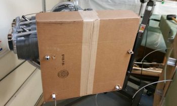
I cut and placed a box that I had just received the second shipment of hoses and hose end fittings from Summit Racing (pretty much finalizing all my hose/fittings orders) over the engine mount/accessory case to protect all of it from sparks and metal debris.
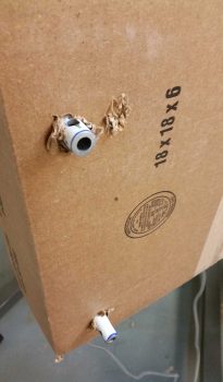
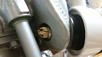
Here’s a closeup of the right side engine mount stubs that needed just a hair trimmed off the front side.
I then spent about half an hour trimming them all up.
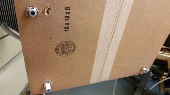
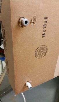
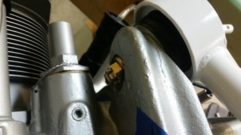
Here the right side stubs are trimmed up and filed smooth.
On my errands yesterday I picked up some hardware and some Automotive & industrial strength fast-drying White Rustoleum paint. I spent a good 30 minutes sanding down the engine mount surfaces with 220 grit sandpaper. Then I filed off a couple very small weld spatters that I missed before, then washed in hot water and Simple Green. I then let it air dry.
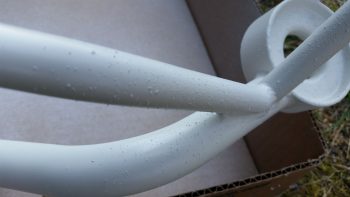
While the engine mount air dried I spent a good 3-4 minutes shaking the can to mix up the new paint… in painting, preparation is everything, right?! I then started spraying. It looked good and sprayed like normal spray paint, but then about 5 minutes into painting the bottom side of the engine mount… apparently my normal spray paint decided it wanted to be a can of textured spray paint. Within a matter of seconds I had the bottom, bottom right corner and right side of the engine mount peppered with what looked like textured, speckled paint.
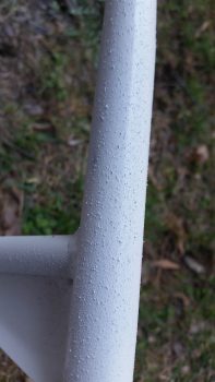
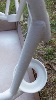
Needless to say I was quite pissed. My saving grace was that this was fast drying paint, so after about 5 minutes I felt a spot and it was what I considered in it’s green state. Another minute more and I was able to rub down the surface with a paper towel with a decent bit of force to remove the spackles of paint over nearly a third of my engine mount. That didn’t leave it feeling the smoothest, but at least the speckles were nearly completely gone. Apparently a glob of paint or something got caught in the sprayer head…. which I cleared out. And a number of test sprays in the air to be certain, I continued on painting the engine mount.
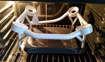
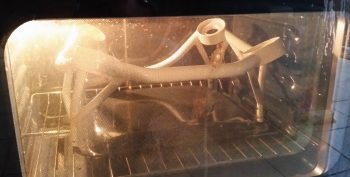
As I waited the requisite 15 minutes for the fast drying paint on the engine mount to dry, I then preheated my kitchen oven to 175° F. I then popped the fairly dry engine mount into the oven and baked it for 30 minutes. My goal here on the engine mount paint is of course to have as nice as paint as possible in a reasonable amount of time, but, moreover, I want the engine mount protected against corrosion and for it to be visually inspectable for cracks (thus why no powder coating).
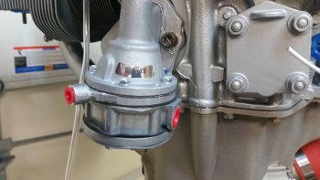
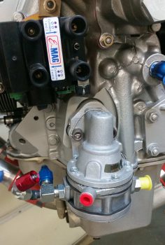
As the painted engine mount baked upstairs, I got to work on the engine mounted mechanical fuel pump. I took some BEFORE pics from both the right and left sides…
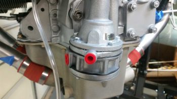
I then mounted the OUT side fitting on the fuel pump, which is a 90° steel fitting that also includes a 1/8″ NPT port straight out for installing a 45° reducer fitting for the fuel pressure sensor line (on the left in pics below). I also mocked up an AN6 90° hose end fitting (blue & red) to test out the angle for how the fuel feed to the fuel injection servo would run, and an AN4 90° hose end fitting (silver & red) for the fuel pressure sensor hose. The aluminum AN6 hose end fitting is just to test the angle. After I verified the angle was the best possible solution I pulled the trigger on a steel AN6 90° hose end fitting from Summit Racing (as well as a 90° 1/8″ NPT to AN3-3/16″ MAP port fitting).
I then installed the fuel pump fuel line feed IN fitting on the right side (as oriented in right pic below).
After getting the fuel line fittings squared away, and turning off the stove to let the just-baked engine mount cool, I took off for a bit to run some errands, grab some lunch, and pick up some 1/8″ thick steel angle from Home Depot for the engine mount mount that I’ll weld up for the engine stand.
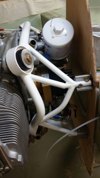
Upon returning home I then grabbed the cooled and cured engine mount and proceeded to remount it back onto the engine. [A point of note: the paint on the engine mount is about a 1 meter paint job…. it looks great unless you actually get fairly close or touch it…. if it were an external component I would probably wet sand it and hit it with one more layer of paint, or clear coat even. Obviously it will be subject to high heat, oil, dust, dirt, etc. in the engine compartment, so I’m more concerned about a robust paint job vs. a sexy one.]
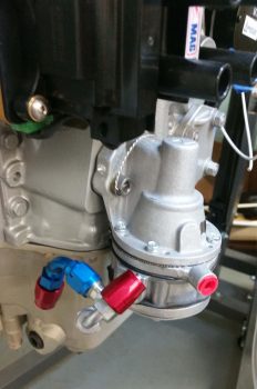
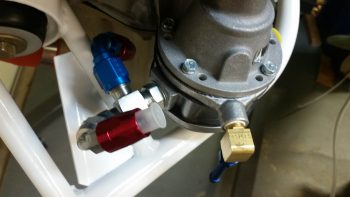
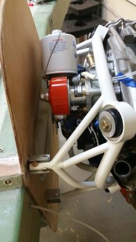
After I got the engine mount remounted to the engine, I then installed the last of the fuel pump’s fittings: the overboard vent line fitting.
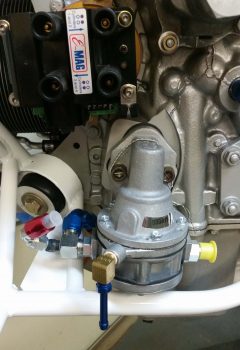
Yet another shot of the fuel pump fittings.
After my airplane building credentials were called into question by a yet to be named Aussie (ok, I give . . . it was Dave Berenholtz!) Ha! I had to prove my mechanical prowess by actually getting the amazingly challenging cotter pins installed on the engine mount castle nuts. Seems like it shouldn’t be that difficult, but the angles and clearances are just killer! (All in fun my friend!).
Here are the top side cotter pins installed in the engine mount bolts and castle nuts.
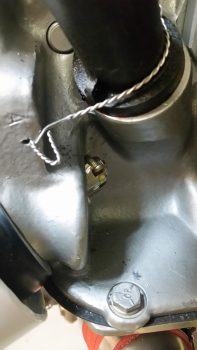
And the bottom left cotter pin installed. I still have no intentions of trying to do this under cylinder #4 and will swap out that castle nut with a lock nut a bit later.
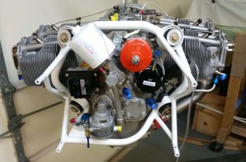
With the engine mount re-mounted on the engine and everything torqued to specs, there was nothing left to do but mount the engine! It was go time!
So here she is . . . engine is mounted!!!
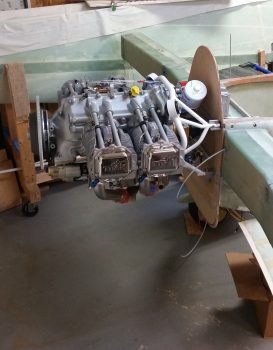
I only had minor issues with getting the last 2 bottom horizontal bolts in place on the engine mount, but after a few minutes of finagling and some light tapping they went right in.
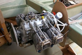
As you can see, even with the eventual fiberfrax and aluminum sheet firewall covering, the clearances are pretty good (by Long-EZ standards) with the firewall. The only clearance concern I have is between the fuel pump overboard vent fitting and the left aileron control tube…. I’ll have to watch that closely.
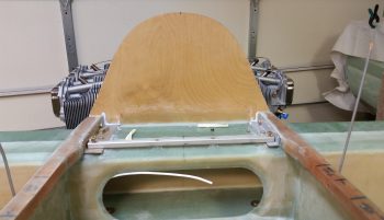
The engine looked a bit small and compact mounted to what I have so far of the fuselage, so wanted to see the cross-section of the engine…. here’s a taste of what that looks like:
Tomorrow I’ll move forward with my engine data collection tasks that I outlined at the beginning of this blog post, and any related tasks as well. Next week I plan on starting on the nose and canopy, and hope to have all this engine stuff put to bed for a while… until final engine install crops up.