
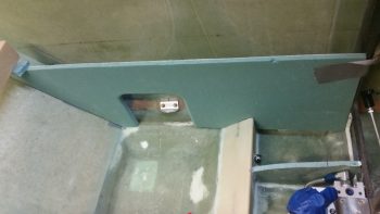
I started out today by pulling the peel ply and cleaning up the pilot thigh support ribs. I also cut out the glass from the mouse hole on the aft side of the right rib along with the overhanging glass from the layups.
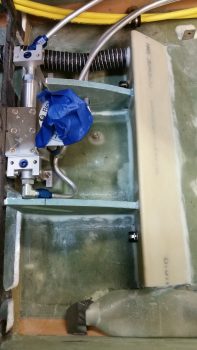
I then trimmed the bottom of the right armrest to provide clearance and eliminate any rubbing on the fuel lines.
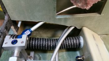
I also notched the bottom center of the left pilot armrest with a triangular opening to allow the armrest wall to fit over the pilot thigh support wedge duct when installed. I also had to narrow the thickness of the wall on the outboard side of it that was adjacent to the air vent plenum duct in order for it to fit in its planned location.
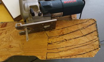
I then got to work on shaping the pilot thigh support seat floor. First, I copied the thigh support rib profile onto a template. Then I used the template to mark up a scrap piece of OSB chipboard to cut out 4 thigh support rib jigs.
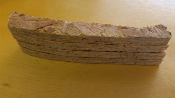
I then cut out the pilot seat thigh support floor piece from 3/8″ foam, and then clamped the 4 thigh support rib jigs to the bottom of the floor piece.
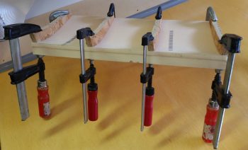
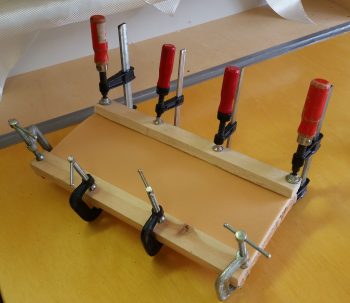
I then baked the jigged & clamped pilot seat thigh support floor piece in the oven for an hour at 280°. In hindsight, it may have a been a bit too long to bake it, but in my defense there was no bake time listed in the plans!
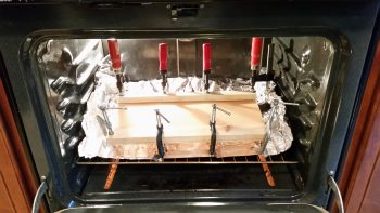
I had to run out for a while after I turned the oven off and the floor piece started cooling down.
When I returned, I noted that there was a bit of waviness in the front & aft edges of the floor piece since the heating of the foam apparently produced some sagging in between the clamped rib jigs. Moreover, these “scalloped” edges were significant enough that I thought about scrapping this floor piece and remaking another one. But I don’t like wasting foam and to be honest, I kind of like the challenge of fixing a piece that’s less than perfect and make it work.
I pressed forward with the floor piece install and started working it until it proved to be unworkable, to see if it would . . . but it didn’t.
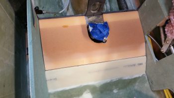
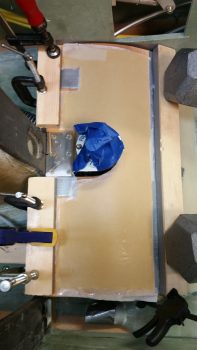
I wanted to lock in the CORRECT floor piece profile, so I decided to do a multi-part layup starting on the top of the floor piece surface (plans has you layup the bottom surface first). Since I needed to clamp both the front and aft edge to lock in the correct shape, I further decided to start with a large central ply of Kevlar –specifically to add puncture strength to a piece that gets stepped on every ingress & egress of the plane– and then add a strip of BID on both the front and aft edges after the center area floor piece profile was better locked into shape. After these first pieces are laid up, I’ll of course lay up a ply of BID over the entire top surface of the floor piece.
As for the Kevlar layup, I started out by microing the surface of the floor piece top where the Kevlar ply will get laid up.
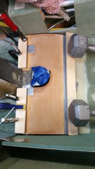
I then set the ply of Kevlar in place on the top of the pilot seat floor piece.
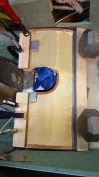
I then wet out the Kevlar.
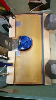
And then peel plied the Kevlar layup.
Tomorrow I’ll continue to glass the pilot seat seat floor piece in my attempt to both get it installed, but also to straighten out some of the front and aft edge waviness that was introduced during my heating of the floor piece foam plate. Still, I think it should be fine.