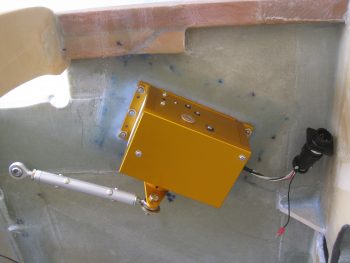
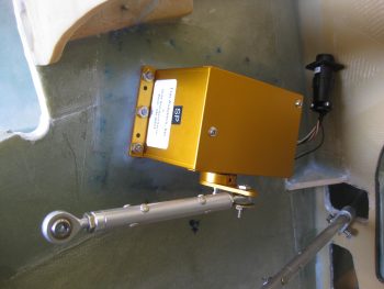
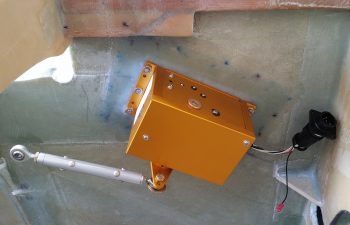
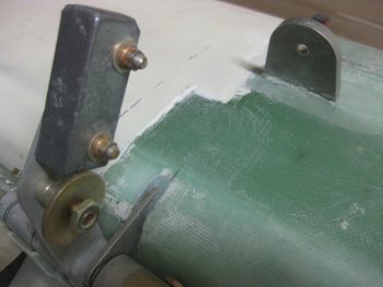
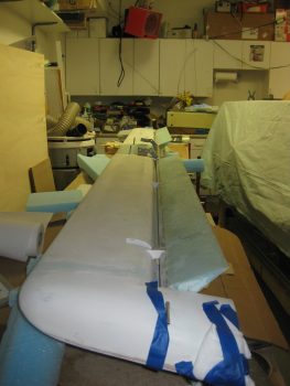
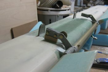
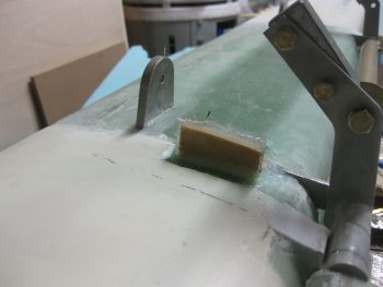
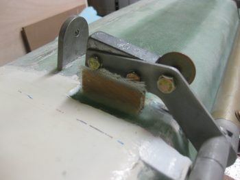
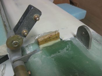
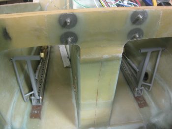
I started today off by peeling the peel ply off the autopilot pitch servo mounting pad & doing some minor cleanup around the edges of the layup.
I then mounted the pitch servo with the control rod in place to show what it will pretty much look like when installed operationally.
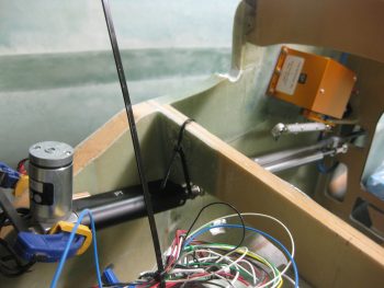
I took the pic below with my phone and included it here because it shows the actual color much better, which is a rich yam orange vs. a sweet potato gold showing up in the pics above.
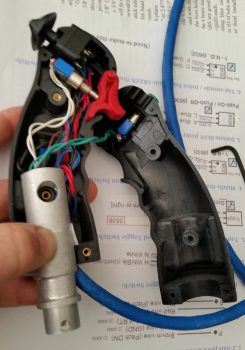
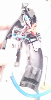
I had to run out and run some errands for a few hours, but when I returned home I went to work on fixing the “crease” that was running down the middle of my Infinity stick grip. Something was misaligned inside to cause a noticeable edge of one half of the stick off from the other.
The first thing I did was to “crimp” the adapter I bought from JD at Infinity to more closely encircle the adapter I made. The second thing I did was reroute some of the internal wires that I think simply had nowhere to go so was bunching up a hair and knocking the halves just slightly askew.
Still, it was the proverbial “herding cats” game but I finally got it. I then torqued the screws down to keep it that way, only to read a few minutes later in the instructions: “Don’t over tighten the screws!” . . . oh, well. They are tight!
So far the problem is solved, but I’ll have to play around with it for a while to see if it regresses before I add blue Loctite to the threads.
For those of you more esoteric types that like more pastel colors, like turquoise, I offer you this . . . I call it, “Nouveau Grip.”
So, there I was . . . it was late afternoon, and the days are getting shorter. Also, this warm weather spell is supposed to end tomorrow so I figured I had better get outside and do some saw work . . . er, uh, I mean some milling work! Ok, milling work on a poor man’s milling machine, aka “a table saw.”
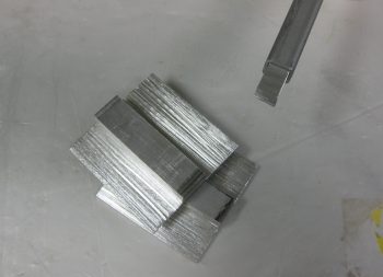
I bought a 2.5″ wide x 0.5″ thick bar of 2024 from ACS specifically to make my inboard mounts for the wheel pants. I did a quick measurement of one of the inboard axle bolts & plate, then marked off the 2024 bar stock for cutting.
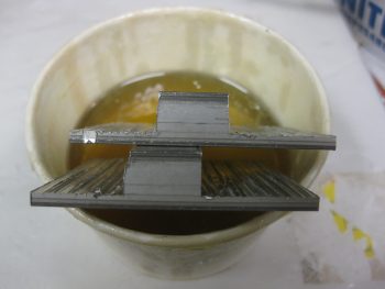
I stole the idea for these from Bernie Siu, who ended up with this style after 2 prior iterations of inboard wheel pant mounts, including the original style called out by Gary Hertlzer in the instructions. These are bit more “elegant” in style, and if all plays out the way I intend, the horizontal “bar” will be able to be used to jack up the gear leg to change tires, etc.
I want to point out that these are in the ROUGH stage, since, as I mentioned before, I had to use the poor man’s milling machine to get these ginned up.
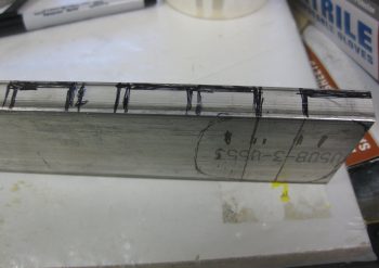
Here’s a profile shot of the wheel pant inboard mounting brackets. I thinned the top and bottom plate material down to 1/8″ by cutting into the 1/2″ bar 3 times, an 1/8″ at a time (for a total of a 3/8″ deep cut).
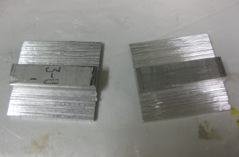
The shot below is more to show the other 2 pieces I cut from the 2024 bar stock, and that’s a 3/8″ x 3/8″ x 1.2″ plug that will go into the end of a 1/2″ x 1/2″ 6061 square tube that I’m using as a crossbar for the GIB top seatbelt straps. Since riding in the back of Marco’s Long-EZ, although not bad at all, I can see where there could easily be a need for folks to bring the top seatbelt straps in closer together.
My bar will be secured in 3 places: on each side with the forward engine extrusion bolt into the CS spar as the original plans upper seatbelt bracket tabs were. And then in the middle of the bar into a hard point in the CS spar. These 2024 square plugs will reinforce the hollow tubing for the 1/4″ AN4 bolt that will get installed vertically through each side of this bar to hold it and also, more importantly, secure the engine mount extrusion in place to the CS spar.
With my metal cutting tom-foolery behind me, I started working on a quasi-requirement of Trio for the autopilot. In the manual it states to not have the autopilot act as the hard stops for the aircraft control system. Although we don’t have hard control stops in most of our Long-EZs, I decided I would do what I could and put in a stop for full aft stick.
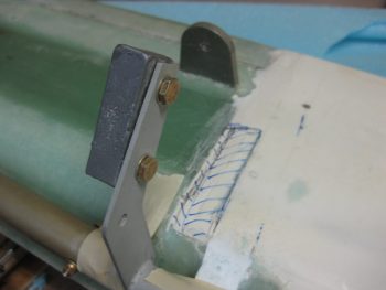
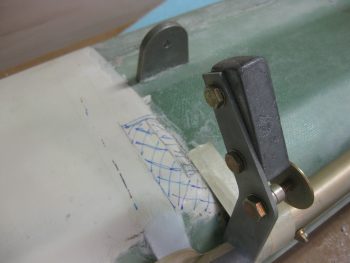
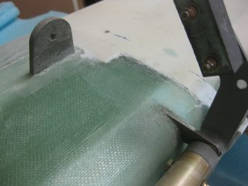
I had originally thought I would put a stop in both sides, under each torque tube offset arm. I may still do that, but for now I decided to just do it under the offset arm where the pressure is getting applied from the control system: the right side. Nonetheless, when I decided this, I had already marked the area on the bottom of the canard where the finish needed to be removed to get to bare glass (below). I did this for both left & right sides.
Here’s a couple shots with the finish removed, and with the glass sanded and ready for glassing.
Here’s a long view with the elevator control hard stop in place. The elevators are set at just a skooch over 30° at about 30.5°, just to make sure the full operational limit is obtained.
In addition to Trio’s requirements (which apparently I’m meeting only 25% of! …. actually, I talked to Chuck Busch and he said all was good with my install plan!), I found an old CP (CP# 48 pg 4) that stated some canard pilots were having issues rotating if they pulled full aft stick and the elevators went past 30° down. This gets into the backside of the lift curve and interestingly may not get the nose of the plane off the ground. As per the CP, in this scenario one would be “on the “back side” of the lift curve, lift is less than maximum and the elevator is creating lots of drag.” Marco was having some of these same type of issues on his plane, and found that NOT going full aft stick on takeoff was giving him better liftoff. Of course I’ll test it out and adjust the stop as necessary IAW this CP.
Here’s a closer shot of the elevator control stop.
I then floxed the elevator control stop in place, made some flox fillets and glassed each side with 1 ply of BID initially. Then, since I had enough epoxy, I added one more ply of BID to the inboard side since my first NON-prepregged piece of BID decided to go just a tiny bit wonky on me. I then peel plied the glass intersection on the canard surface.
Later in the evening, I reinstalled the Infinity stick grip in the arm rest and tested it out. Alles ist gut! . . . so far.
I realized the other night that my initial estimations on where the rudder pedals needed to be mounted were way off! I guess I’m just a lot taller than I remember (ha!) because twice I had to remount the rudder pedals farther forward. In addition, the space in the nose is TIGHT, and I may have to lop off the inboard tubes that make up the “T” on the rudder pedals. Currently, it’s just too difficult to set my feet along side them as if I were in the relaxed cross country mode, then bring my feet back onto the pedals. My shoes snag on that top pedal crossbar and make it a real hassle to get my feet back on the pedal. Since it’s so narrow on each side anyway, I doubt if lopping off that extra metal tubing will affect my ability to mash these pedals when needed!
With a really good idea of my pedal geometry now, I decided to re-attack the placement of the Atkinson pitch trim assembly. After mocking it up in different spots for a bit, I pretty much concluded that it has to go where I had planned for it to, except with one minor modification: it most likely will have to be mounted at an angle with the actuator motor leaning from 30-45° inboard to clear the upper curvature of the nose.
Tomorrow I have to get some work done on my truck, then run some more errands. I plan on finalizing some more of this perpetual odd-n-end stuff and hopefully move onto doing stuff that’s actually covered in the plans!

