
Today I started out by refining my wheel pants prep & wing mounting to CS spar plans.
I then discovered that my UPS friends had delivered my ACS order, and yet another Mouser order. I logged my new parts in my spreadsheet, sorting through the myriad of CAMLOC bits ‘n pieces & more new panel switches. I identified all the switches, labeled each one, and stowed them away with all the other switches.
One new item of note that I received today is the TCW Technologies 3-Amp hour Integrated Backup Battery System (IBBS). After W&B discussions with Marco regarding his new Long-EZ, he had advised me to literally front load as much component weight possible into the nose region of my plane to favorable counter the sensitive rearward balance tendency of Long-EZ’s.
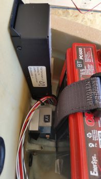
As I mentioned in a previous post, I had originally planned to install a 3AH model IBBS since it would serve me well enough –and for the specific reason that I would be saving weight over the 6AH model. So upon the “load the front heavy” advice I received from Marco, I assessed putting in the bigger model. Ah, but alas, the 6AH model was physically too big to mount it where I had planned (see pic below) so I went with my original plan and pulled the trigger on the 3AH IBBS.
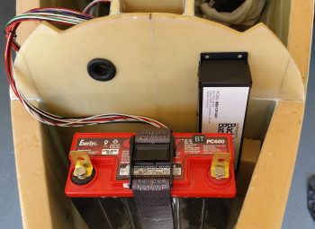
As you can see in these pics, the 3AH IBBS fits perfectly… and according to plan!
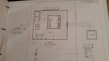
After getting all the first half of the day’s miscellaneous tasks out of the way, I started in on something I’ve been trying to knock out over the past few days. You see, Marco has been diligently working on the pitot tube wiring system for our Long-EZs, and I haven’t been the best teammate in assisting with the effort (See Marco’s latest post regarding the pitot tube electronics on his blog). Moreover, a number of days ago Marco asked if I could draft up the wiring diagram (#24) for the Heated Pitot Tube Electronics. Thus, a main goal I had today was to get this sucker knocked out, which I did below. Of course there will be a bunch more mods to this diagram as we move forward, but as of right now we have a good baseline schematic for the pitot tube electronics!
After completing the heated pitot tube wiring diagram, I then went down to the shop to get some work in on the wheel pants. My current issue is one that many builders seem to be confronted with, but oddly enough I’m starting to see a possible nascent trend that only 400×5 tire users seem to be afflicted by ? . . . and that is that until some type of slots are cut into the bottom of the wheel pants for the tires, the front and back half of the wheel pants can’t be mated together. Nate Mullins certainly had this issue.
As it goes during many a times during this build it was time to take yet another leap of faith and cut into the bottom of the wheel pants. Of course I don’t know exactly where the wheel will reside in each wheel pant, which prompted me to look at a myriad of pics from other builders’ installs. I decided to shoot for center mass: 4″ forward on the front side of the wheel pants and 3.3″ aft from the front edge of the aft side wheel pants.
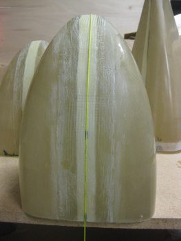
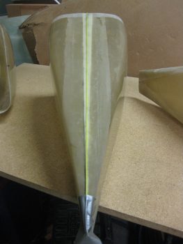
Since I would destroy the bottom CL mark by removing the glass on which it resides, I decided to move the CL marks out of the lines of fire on all the wheel pant parts. I grabbed my tape and a plumb bob line and ran the line down the CL of the wheel pant… Uh, except maybe I should aim for the correct side of the wheel pant! (I started on the top of the wheel pant in the pic below, but luckily I caught my error!)
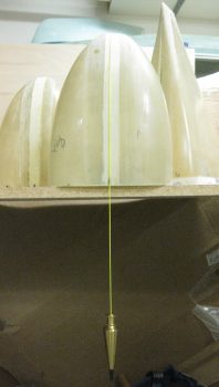
Ok, the BOTTOM of the wheel pants… this is much better!
I then marked the aft edge of the front side of the wheel pants for certain destruction and mayhem! Hoo-ah!
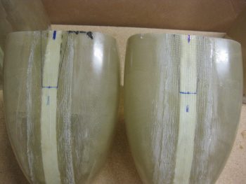
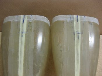
I then extended the centerline mark rearward on the aft wheel pant pieces as well.
And marked out the areas of certain destruction on these as well!
After cutting out the notches in each side of the wheel pants, I still couldn’t get the aft flanges into the front side receivers! I ended having to extend the notches another 1/2″ forward and aft, respectively, into the wheel pant assemblies.
Voila! It finally worked [BARELY] and after a fair bit of wrangling –and 3-1/2 years!– I finally was able to mount the back part of the wheel pants into the forward assemblies for the first time ever! And I bought these suckers from Sam James back in January 2013.
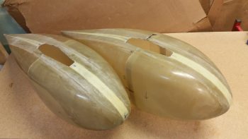
Here’s the first shot of my wheel pants assembled into one single unit per side! However, the fit is still really tight so the first order of business tomorrow is to give the flanges and receiver mating surfaces another intense round of sanding.
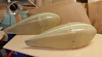
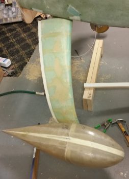
Excited to see actual, assembled wheel pants, I set them next to the gear strut for a quick mockup just to get a feel for the general size and shape.
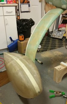
Another shot of my quick wheel pant mockup.
Now that I know the wheel pants actually mate together (and that none of the vertical or horizontal centerline marks are off by more than 0.1″), I’m really happy and confident that the wheel pants should mount & fit nicely over the wheels and onto the gear struts!