
. . . . with a sense of purpose!
I tested out my cell phone camera and although the portrait/landscape indicator is not working, apparently the camera is still automatically orienting itself correctly. I took a short video to show the installed Matco parking brake valve lever cable push/pull actuation.
I then cut a piece of 3/8″ foam for the initial approximately 3″ that makes up the start of the wedge shape that is the pilot’s seat thigh support. Basically what I’m doing is make the aft few inches of the pilot’s seat thigh support a triangular built-in air duct. Obviously the aft side of the 2 interior thigh support ribs will now have their tapered aft ends cut “square” so they mate up with the wedge-shaped duct that I’m making below. This is all to get the warm air over through the duct system to my right foot. Gotta keep those tootsies warm people!
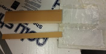
After I cut the top 3/8″ piece and shaped it, I then cut the front upright –or front wall- of this wedge-shaped duct. This smaller pieces is 1/4″ foam. Since I had a scrap piece of BID that would cover half of the internal side of this wedge duct assembly, I simply cut the other half off the roll and went with 2 pieces (1 ply) of BID. As per my norm, I prepregged the BID.
The entire width of the thigh support is 17″, the same as a stock plans-built Long-EZ. A long time ago, when I widened the fuselage 1.4″ at the pilot seat bulkhead, I was more concerned about space at the shoulders. Thus, instead of widening the thigh support (the aft seat pan is a bit wider since the bulkhead is wider) I focused on widening each armrest a bit more.
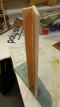
I then used fast hardener to mix up some micro to glue the 2 foam pieces together. (Unfortunately, this effort wasn’t simple and required a good hour of trial and error fitting & some resanding to get it all dialed in before joining the 2 pieces, thus the reason for the overhang of the top piece you can see in the pic below). I held the small piece in place with pins to immobilize it as the micro cured.
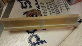
I spent a good hour prepping some other tasks while the micro cured, then while it was still tacky but structurally sound I laid up 1 ply of BID on the internal side of the wedge PIC thigh support duct. I then peel plied it at the BID ply overlap and each end.
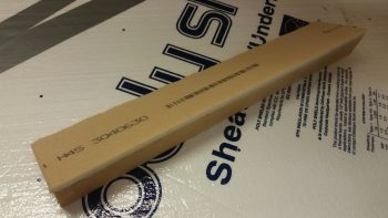
A couple hours later, after the glass was cured, I knife trimmed the glass and cut off & sanded the front overhanging piece of foam.
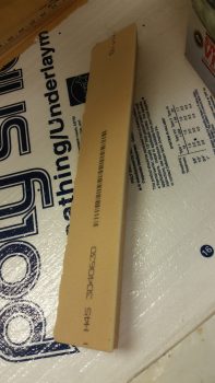
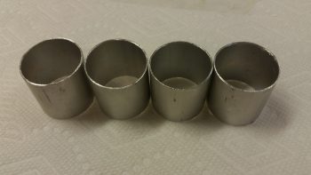
I then took my 1.25″ OD x 0.0.35″ walled 6061 aluminum tube outside and cut 4 each 1.25″ long pieces for subsequent use for connecting the 1.25″ ID SCAT tubing to the respective ducts that require it. I then spent a good 20 min cleaning up the edges on all these duct tube transition pieces.
As far as ducts in the duct network that “require” a SCAT tube interface, or cross connect, I determined that with the COMM & NAV COAX antenna cables being situated right behind the air duct as it initially enters into the PIC area through the lower left pilot seat, that I should make the transition over the left seatbelt mounting bracket SCAT tubing vs. glassing a hard, permanent duct.
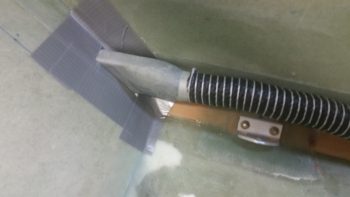
As you can see, when I finalized the shape of the duct coming out of the duct hole in the lower left pilot seat, I simply ran it out a few inches and capped it with one of the aluminum tube pieces I just cut.
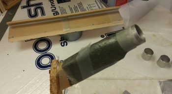
The duct tape around the hole in the pic below was for making a flange on the duct that would allow me to later flox the duct piece in place. Instead, I won’t be using that tape and will simply attach the duct piece to the lower left pilot seat with small BID tapes.
I’ll also note that I had planned on not having any of this duct piece enter the seat back duct cutout, but I then decided to leave a good lip so that it would be much stronger, and so I wouldn’t have any duct alignment issues. Yes, it will cost me a very slight penalty in airflow, but since I’m reducing my tubing diameter anyway by utilizing the 1-1/4″ ID SCAT tubing, I think it will be matched fairly close regardless.
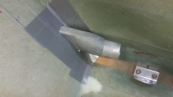
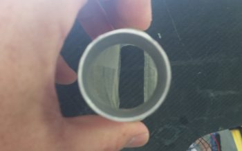
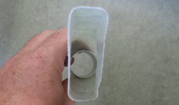
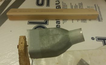
Here it is with the SCAT tubing slid in place. The area at the far right of the pic below is where this SCAT tubing piece will end and reattach –via an aluminum tube insert– back into the glass ductwork.
Here’s a couple shots showing the internal dimensions and airflow of the duct piece.
As I’ve already noted, I decided to make the duct transition over the left pilot seatbelt bracket SCAT tubing, primarily to ensure I can run my COAX antenna cables somewhat pain free, but I have a requirement to do something along that lines at the front part of the pilot seating area at the instrument panel as well.
The hole in the lower left instrument panel is a rounded square hole that my throttle handle cable connector needs to fit through. And it can just barely fit if I remove the Adel clamp (IIRC!). What is certain is that the throttle handle cable connector will NOT fit through that hole (for mounting, servicing or upgrading) if there’s a permanently mounted glass air duct running through that hole. Yes, I could glass a unique removable duct to go through there, but running a length of SCAT tubing is just the easiest & fastest option. By using a length of SCAT tubing to transition the instrument panel, then I ensure that both throttle handle cable connector remains removable as does the SCAT tubing. Moreover, they’ll fit and play nicely together.
Taking into account all I stated above, then what I have in the lower middle area of my left armrest is a 2-headed snake, one at each end. I have an aluminum tube connector ⇒ glass duct ⇒ aluminum tube connector. Hmmm… if this is the setup then you may ask why not just run SCAT tube the entire length under the armrest from point A to point B? Well, because there’s a point C. In between these 2 aluminum tube pieces that connect to SCAT tubing, is the duct outlet that flows through the wedge-shaped duct at the front edge of the pilot thigh support. Again, this carries air over to the right foot vent.
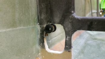
Since I want to minimize the footprint of the air ducting under the left armrest, I’m trying to follow the contour of the cockpit seat pan & floor as best possible. At the corner junction of the fuselage sidewall and floor (seat pan) the contour actually changes. To allow for this I made up a front duct foam form and a separate aft side duct foam form, each with an aluminum tube connector to cross connect to SCAT tubing. (These will be joined together into one duct after they are glassed separately and I pull the foam plugs).
Since the front side of this under-armrest sidewall glass duct “plenum” was the more complex of the 2 ends, I decided to knock it out first. As per usual, I made up the form with urethane foam and then covered it with duct tape. Normally these ducts are made by taping up the foam to the sidewall and using the sidewall as part of the form, with a resulting flange created on the duct used to mount the duct later on. However, since the space is tight with the left armrest upright sitting adjacent to this duct AND the requirement to glass all around the aluminum transition tube, I went ahead and glassed all sides of with it out of the fuselage. However, the bottom side is mainly open so that the existing fuselage corner will still act as the duct bottom wall.
Tomorrow I’ll continue to work more on the pilot seat area duct work. Since I have the initial pilot seat back duct piece completed, I can now better figure out some of the cable control routing to the 3 duct valves aft of the pilot seat.