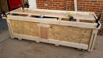
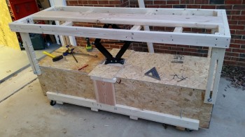
I did finish the major build tasks on the fuselage dolly, but allow me to cover the day chronologically:
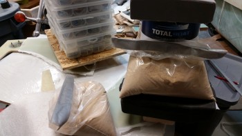
I started off this morning checking the NG30s’ outboard side layups. I failed to get this pic in the mix last night, but it’s essentially a bunch of heavy stuff that I balanced on separate 2x4s that are resting on plastic over the 3 hard points I just glassed, on each NG30.
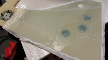
When I pulled everything off, here’s what I found. Nice & flat!
And then I pulled off the peel ply.
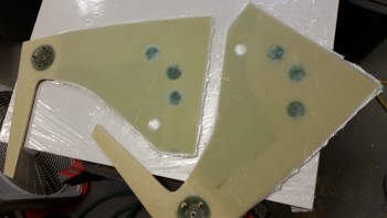
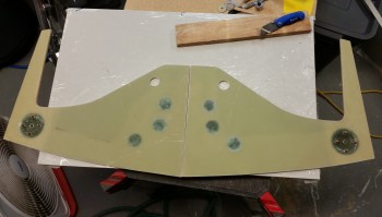
And here’s the finished product: Edge-trimmed & sanded NG30s ready for attachment to the F22 bulkhead.
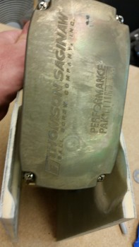
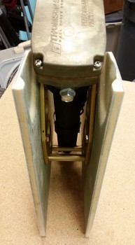
I re-drilled the gear actuator mounting bracket holes and put the NG30 nose assembly all back together to check fit & clearances. As you can see, it all looked good and went together smoothly. I checked the inside measurement of the NG30s and it’s almost exactly 3″, so the width is spot on (it would actually be a little tough to be off with the configuration as it is, with the mounting bracket spacers and all, but still, good to have the right numbers!)
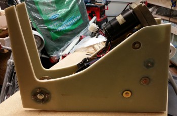
Nose gear actuator, nose gear pivot (NG6B) and NG30’s ready for install!
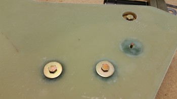
Here’s a good shot of why I filled in the hard point depressions. As you can see below, the washers sit nice and level on the new glass and there’s no concern over torquing these very important bolts down to the right value. Nice, clean & EZ!
After all the work on the NG30s was done for the day, I spent about an hour upstairs researching parts & electrical connectors for the nose gear actuator (I really don’t care for Molex connectors in an airplane so my plan is to swap them out for AMP CPC connectors, as my buddy Dave Berenholtz did).
I then opened up the garage and got to work on the fuselage dolly. My first task of the day was to get all the corner support struts built and attached. These are essentially the corner table legs that keep the top fuselage table mount steady and secure at each elevation.
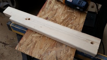
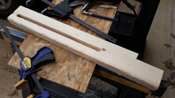
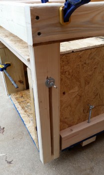
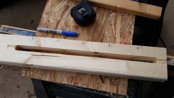
The support struts are simply 2x4s with a 5/8″ slot cut down the center so that a stationary 1/2″ bolt mounted on the lower box slides through the slot. Then, when the table is at it’s desired elevation, I simply tighten the 1/2″ wing nuts and secure the table mount in position. A point of note is that I intentionally made the slots in the support struts a little oversized at 5/8″ compared to the stationary 1/2″ carriage bolt (which protrudes through the strut slot) to ensure there was wiggle room in the sliding action to prevent any unwanted binding.
Here I’ve positioned a corner support strut and am marking the upper point to be drilled out with a 5/8″ auger bit.
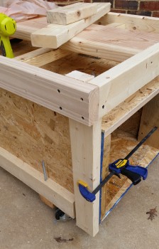
Here’s a corner support strut ready to be permanently screwed to the table platform.
Side view of fuselage dolly with the corner support struts ready to be permanently mounted to the table platform (top work/mounting surface).
I had also done a bit of research on creating ratchet arms as a safety mechanism since I’ll have a fair bit of weight on this table. The scissor jack can easily support & lift 5,000 lbs, but the area that it supports is less than 1 sq. ft., so these corner struts are vitally important to the stability of the load on the top table platform.
So although I haven’t designed or made the exact ratchet pawls, I went ahead and notched each corner support strut every 3″ starting from the bottom of the strut for the ratchet pawl to engage with once I make & mount them.
An updated pic with ratchet notches on the support struts:
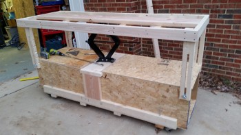
This is a pic I took immediately after testing out the raising and lowering of the table platform. So far my plan is working as designed!
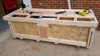
This is pretty much the same view as above, but some minor additions have been made such as cross supports at the end of the table platform and the final install of the lower decking immediately adjacent to the scissor jack on each side.
You may notice in the pics that the scissor jack is not at its full extension height. This means the height of the table platform is being limited by the length of the slot in the support struts, not by the scissor jack. I have already planned out additional steps I can implement to allow the scissor jack, and thus the table platform, to reach its max height… IF I really need it to go that high. We’ll see if I need to go that route during future build tasks.
It is getting dark much faster these days, and that will be even more accelerated here on the east coast as tonight we change our clocks for daylight savings time. Thus, by the time I had the top mounted it was fairly dark, so I lit it as best as I could. After turning on the outdoor lights there seemed to be enough that instead of just taking a simple picture, I figured I would attempt to make a video to show the fuselage dolly in operation.
Now, I didn’t narrate the video because I did this on a whim, and I had music playing fairly loudly in the garage. However, the mike on my phone hardly picked up the actual volume of the music, so the video seems like a silent film to a degree. Yes folks! I’m that lazy that it pains me to now talk during my videos! Ha!
Oh, one other note on the video. In the video I appear to be hunting & pecking around for the hex drive on the scissor jack that is situated towards the center of the table under the table platform (If I haven’t mentioned it before, I angled it towards the corner for easier raising/lowering operations when the fuselage is mounted on the table platform). My point is that it’s actually very easy to see and engage the scissor jack under the platform, it was just more difficult & time consuming to attempt it while trying to film the process with a phone in my hand.
Ok, a very final note on this video: the canopy is inside the lower box with the end caps screwed in place, making this a very secure housing for the canopy until I get to Chap 18.
