
Fuselage Exterior
1 June 2012 — I got a late start tonight because I went to the German equivalent of Lowe’s, Praktiker, versus the German version of Home Depot, Hornbach. And yes, they are even Blue vs Orange. By the time I got home it was past 10 PM and I wasn’t going to test the local noise ordinance, so I went into planning mode.
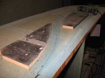
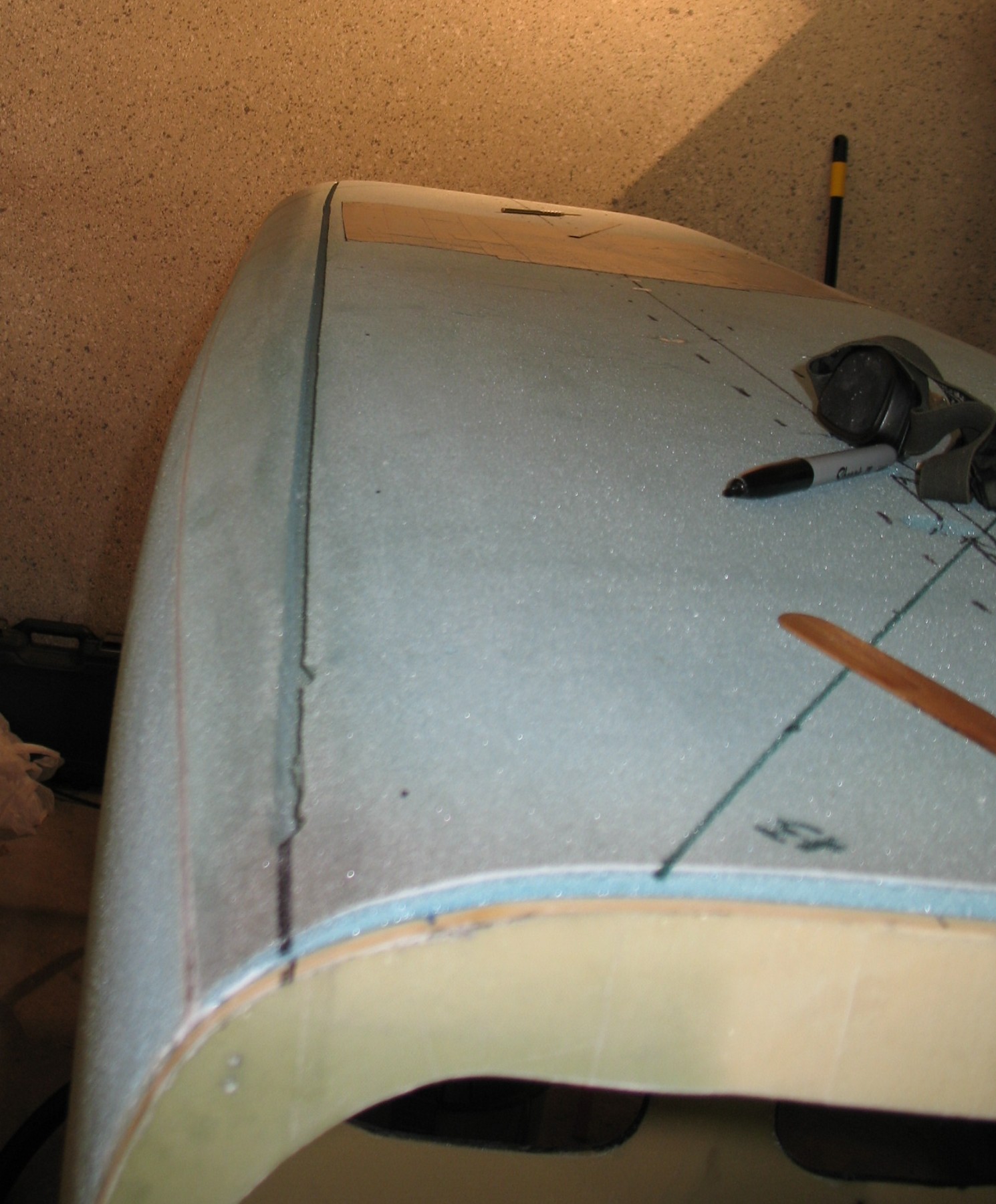
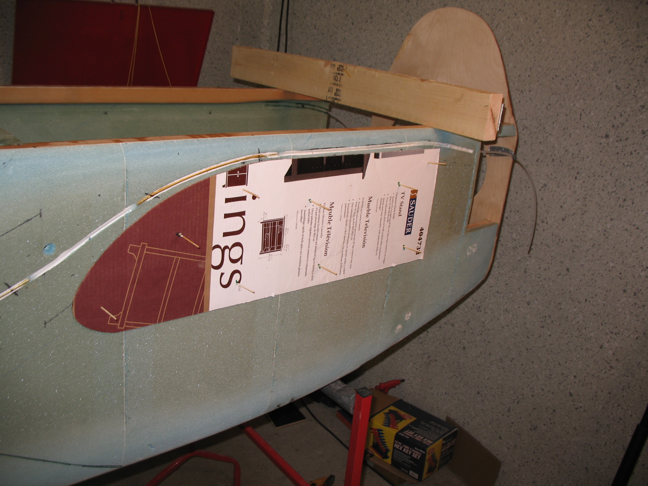
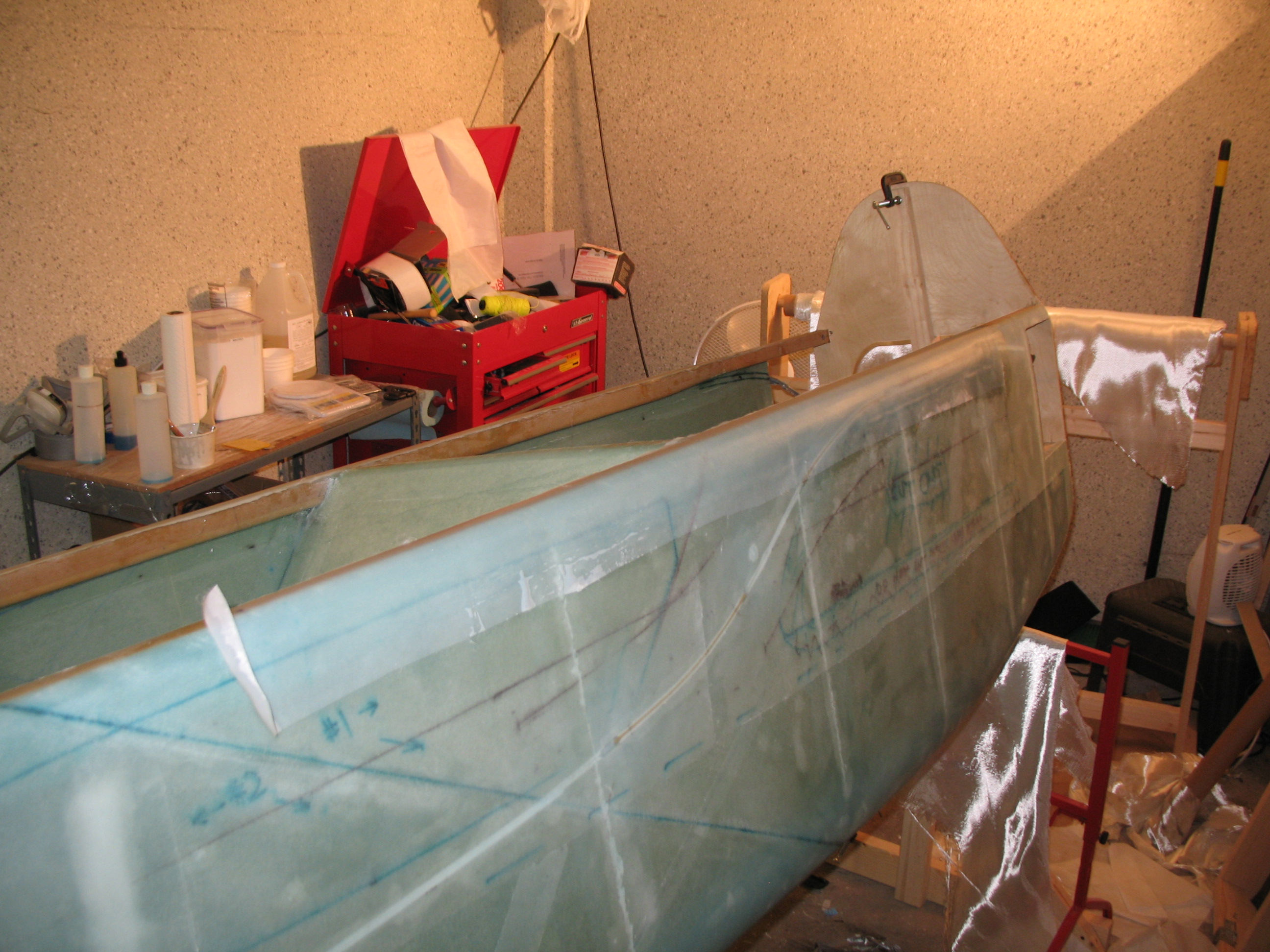
I planned out, and then drew the lines for the Nylaflow rudder cable conduit runs on the side of the fuselage. I then traced the ‘S’ curve onto trace paper for templates. I had some spare particle board from a cheap shoe rack that was damaged in the move, so I used those pieces to glue the templates to using 3M’s 77 spray adhesive. I would cut those out first thing the next day (Saturday).
Since I would be in wood working mode, I also quickly designed and set up cuts on some particle board I had shipped over to make a UNI glass stand to use when glassing the fuselage. Once the stand is built, I can simply bring a whole roll of UNI out to the garage and cut right off the roll as I need it.
Knowing that I was going to be installing the brackets for the seat belts in the not-too-distant future, I marked up a 2024T3 aluminum angle piece for all 4 seatbelt brackets for the interior of the fuselage. I planned to cut those as soon as I got the chance.
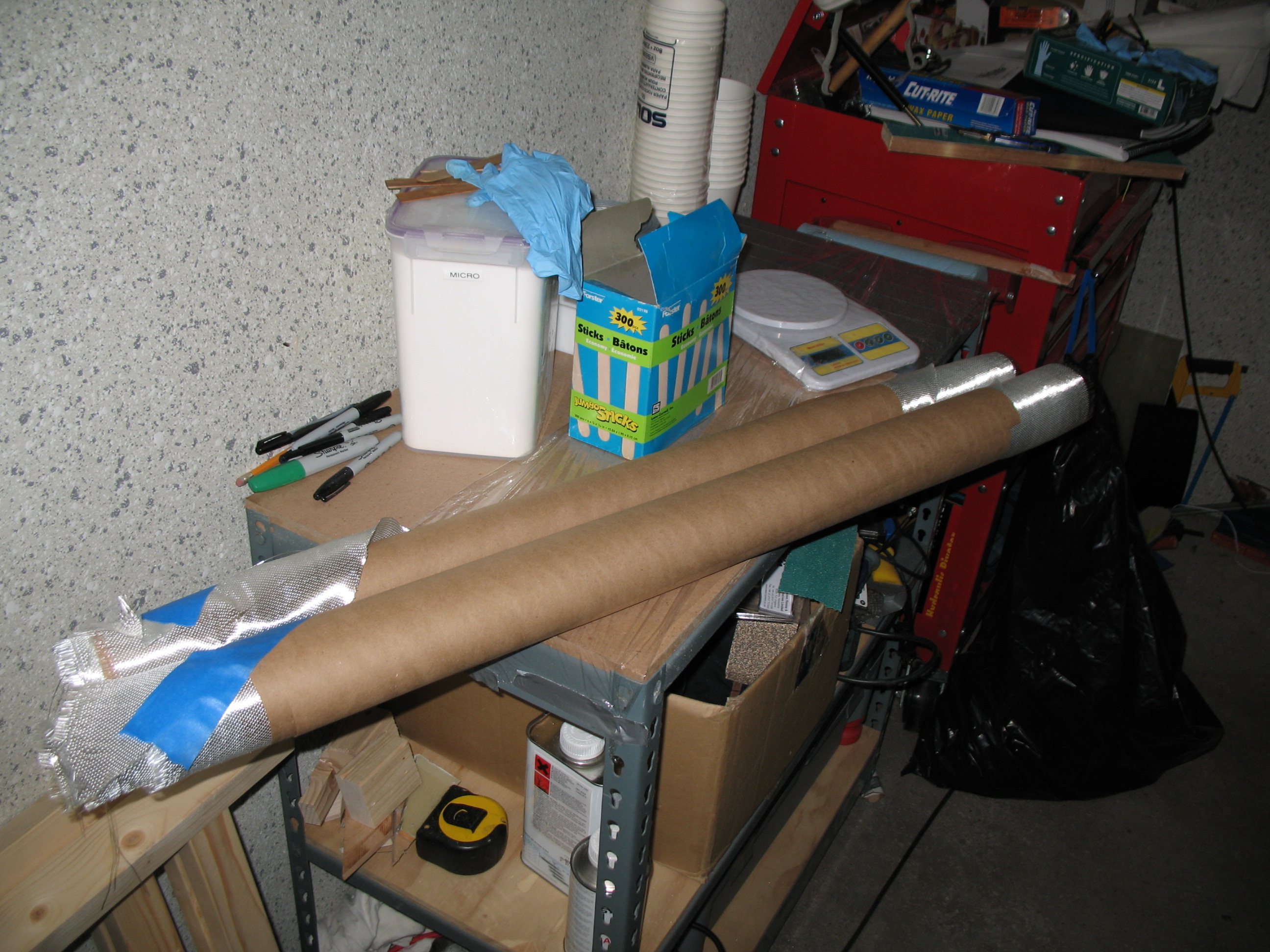
Lastly, in prep for the upcoming fuselage skinning, I put together a small metal workbench about 20″ deep by about 30″ wide with a top bench surface and two shelves for my garage shop epoxy station. The time was coming where I would need to make a lot of epoxy, micro and flox without hauling it out to the garage from the shop inside the house.
•••
2 June 2012 — Today was an amazingly busy day for the Long-EZ project.
I made the initial cuts on the seat belt aluminum angle extrusion, and also planned and marked the bolt hole positions for the seatbelt/bracket attachments.
I dismantled the Fuselage Bottom’s sled and reclaimed the three 2x3s for the UNI glass stand that I designed last night. Then I went to the woodshop on Ramstein to cut the wood for the UNI glass stand. Being an avid wanna-be consolidator, or maybe opportunist, I also cut 4 each 1″x1″x3″ Spruce blocks for the CS spar imbedded hard points (these will come into play A LONG TIME from now!). I then cut some 1/4″ plywood into 2.4″ and 2.5″ strips for some future templates.
After yet another BAD experience of dealing with the ‘Know-it-all Nazis’ at the base wood shop, I decided I’d had enough. Besides being a pilot, my Dad was both a contractor and a cabinet maker, so I grew up on just about every wood-working tool known to man. And these wood shop guys on Ramstein treat every person in their presence as if it’s the first time they’ve ever seen a power tool. Thus, although I have crates of power tools, saws, etc. in storage somewhere in Virginia, I marched my happy butt over to the Base Exchange and bought a small 7-1/4″ chop saw to lessen my interface with those knucklefutzes, and thus lower my build time, decrease my angst, and maintain my sanity!
I went to the German version of, oh, we’ll call it True Value Hardware, Toom, and bought some Dremel bits and then returned home.
Ok, back to work!
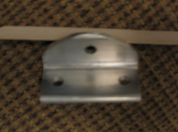
I drilled all the holes in the seat belt aluminum angle extrusions, and then cut one bracket completely out and filed down the edges. Although not a perfect specimen of machining, it looked pretty good! (Pardon the pic, I know it’s quite blurry)
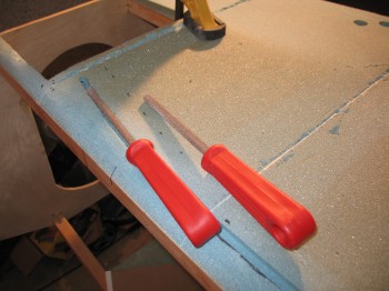
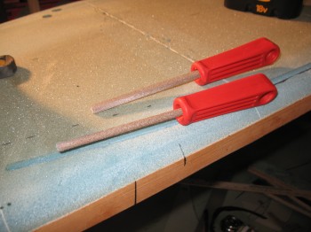
I then went from metal “machining” mode into woodworking mode and cut out the Dremel Tool templates—for routing the rudder cable Nylaflow conduit channel ‘S’ curve—out of the scrap particle board.
Since I had all my woodworking stuff out, I decided to knock out the UNI glass stand. I cut out a few more pieces (I did all the ‘heavy-lifting’ cutting at the base wood shop) and then finished building the UNI glass stand.
I took a break and talked to my buddy Marco to confirm some ideas and measurements (Steve Volovsek’s strake elbow-room mod, F22 center post width, Landing Brake LB22 & LB 23 dimensions, etc.). After our 1-hour long “strategy” session, it was time to get back to work.
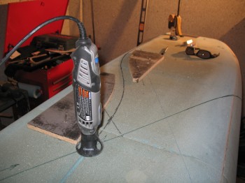
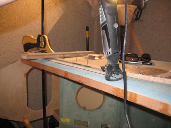
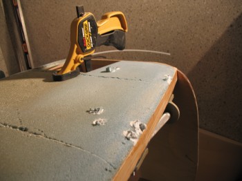
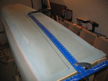
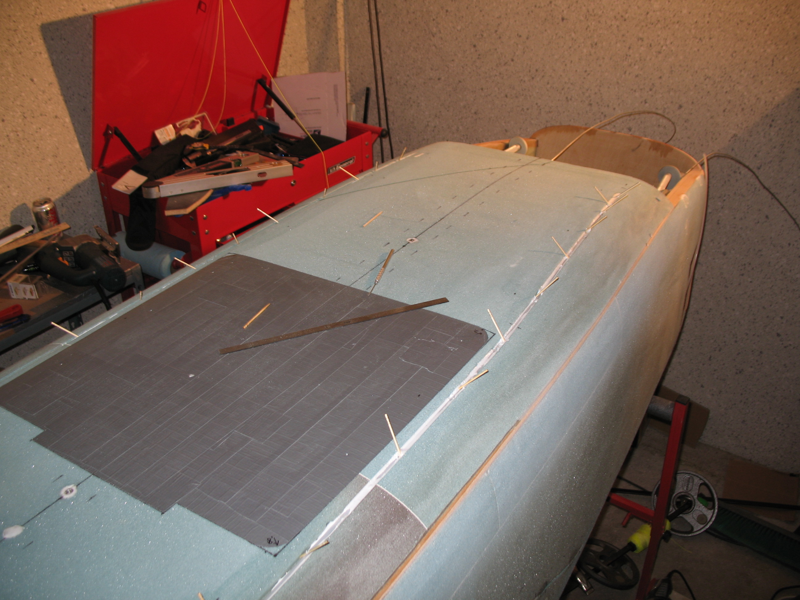
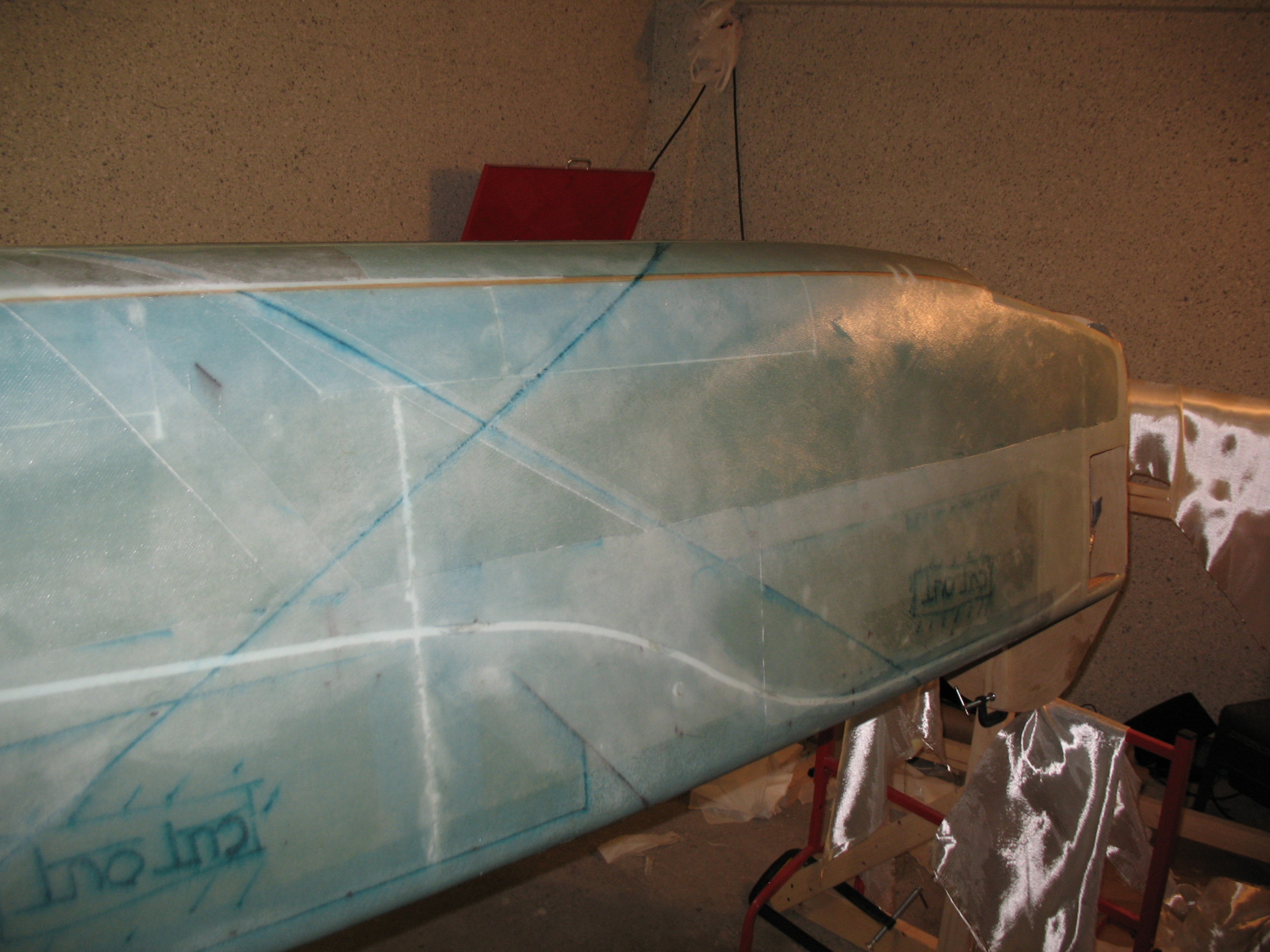
I set templates and then set up the Dremel tool. After double, triple, and quadruple checking everything, I pulled the trigger (literally! ha!) and Dremelled the channel along the Left side of the fuselage for the rudder cable conduit (Nylaflow).
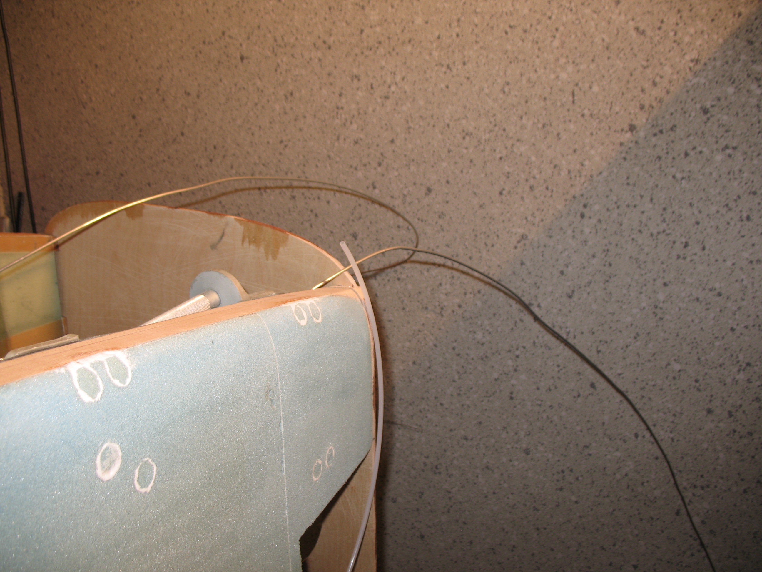
I also carefully drilled the holes at each end of the fuselage: AFT END – For the conduit to continue through the CS Spar and curve towards the outboard winglets . . .
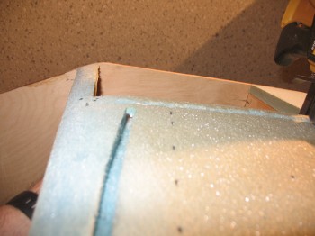
FWD END – To continue into the forward fuselage near to where the rudder/brake pedals will be positioned.
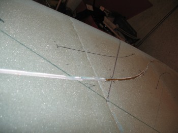
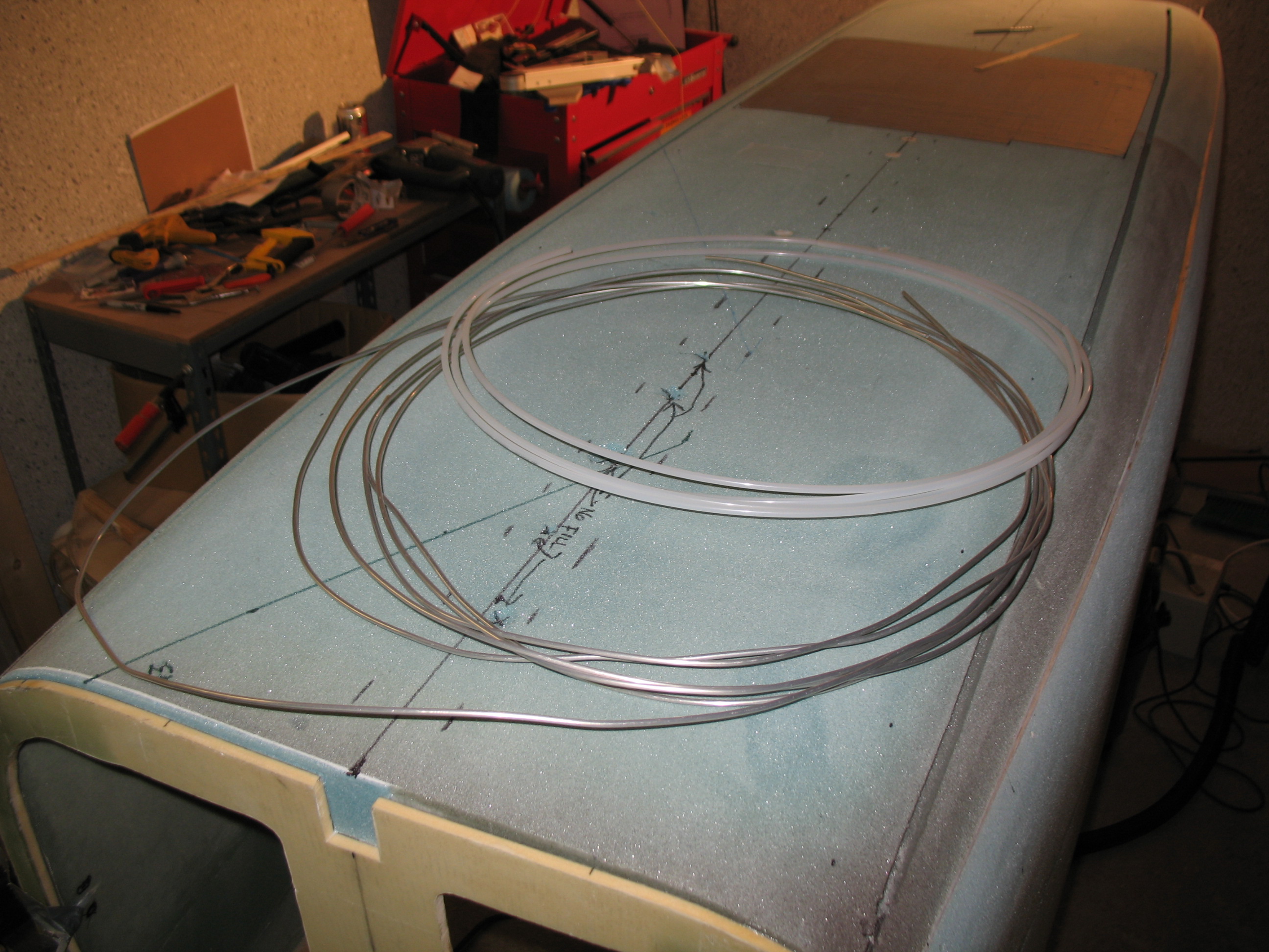
Although Nylaflow is some tough stuff, with a little bit sharper bends at the ‘S’ curves compared to anywhere else in the rudder cable conduit system, I decided I would reinforce it with some metal. I didn’t have any aluminum tubing, so the next best thing I could find locally was brass (at least that’s what it translated to!). I cut the brass tubing into two 9-7/8″ lengths for each side of the fuselage. I then chamfered the openings at each end. I cut 4″ of each end off of the 30″ long spring used for the trim system and set those pieces aside. I then used the remaining middle 22″ for shaping the brass tubing. It worked like a champ and didn’t deform the tubing at all.
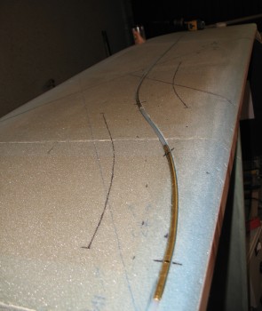
Once the brass tubing was bent and in place around the Nylaflow conduit, I micro’d the entire run of Nyloflow and brass tubing and held it into place with toothpicks.
Also, since I had the micro out, and still trying my hand at that efficiency stuff, I micro’d some foam chips into the main gear extrusion bolt holes in the foam.
•••
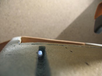
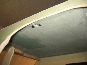
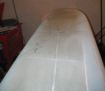
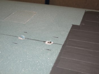
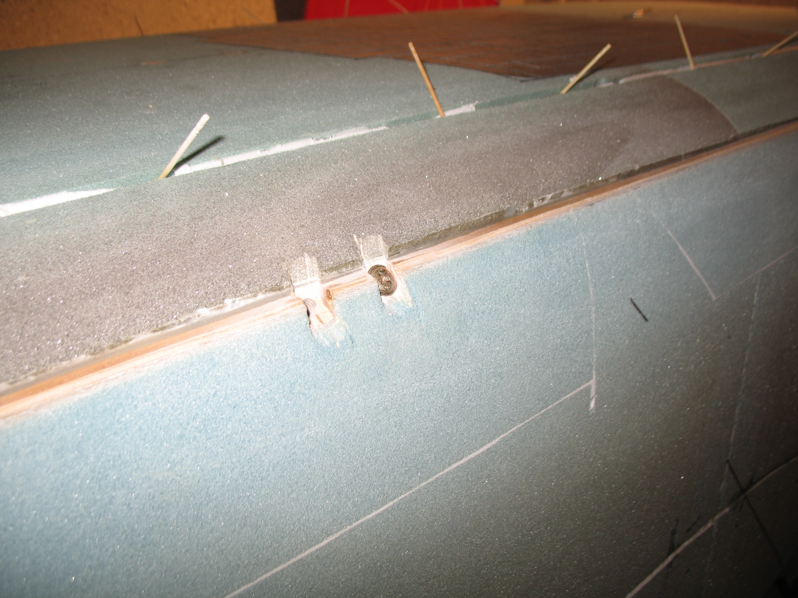
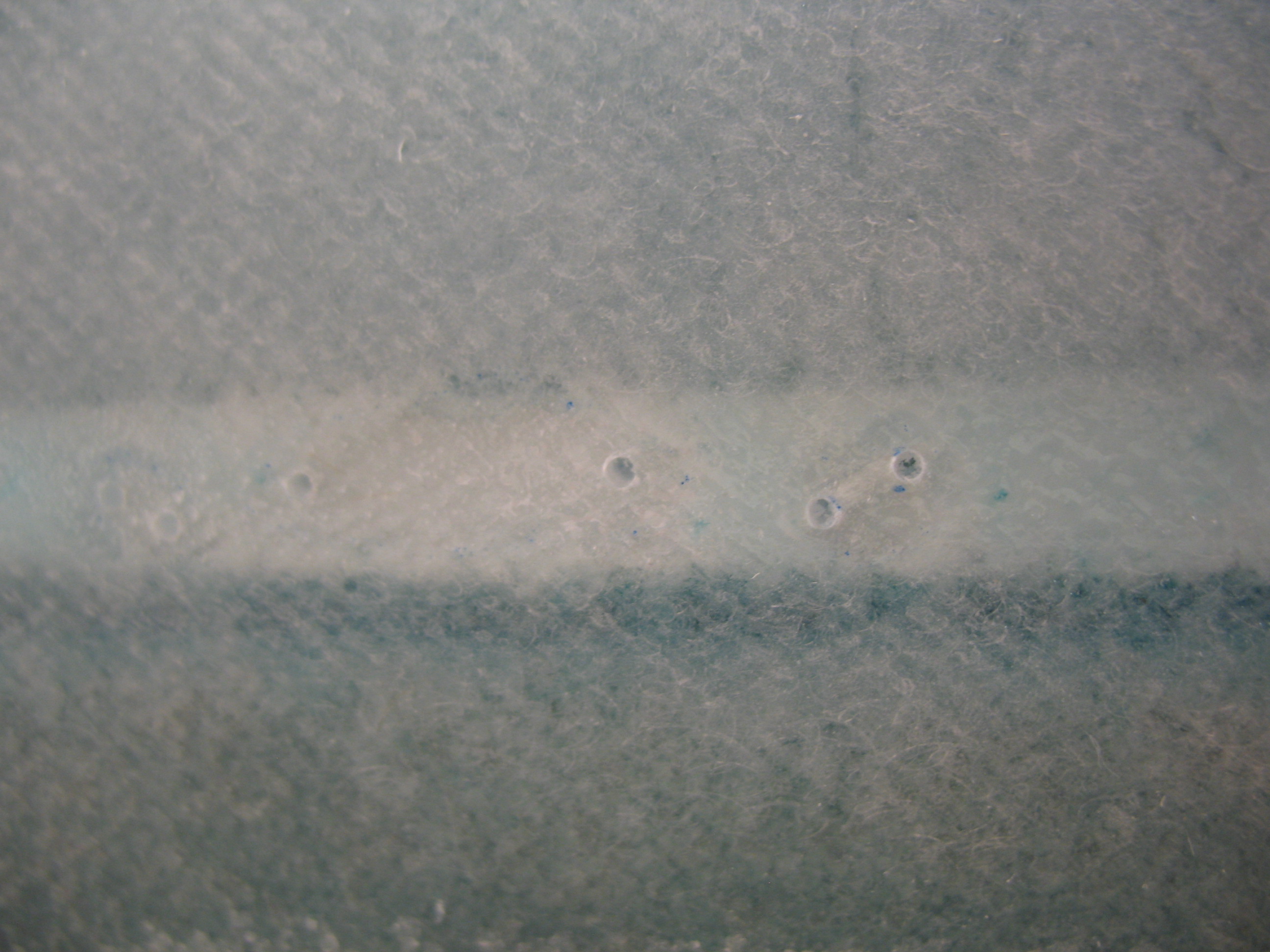
3 June 2012 — I checked the micro that’s now embedding the rudder cable conduit that I laid into the channel along the Left-side fuselage last night. I knocked off a couple of errant spots of micro that intruded into the airspace above the surface of the foam. I also checked the foam chips micro’d into the main gear bolt holes and snapped a picture of them after I cleaned up the area and sanded down the bolt hole inserts.
It all looks really good. The only downside is that 3 of the 4 pictures for today’s post are of the Left side of the fuselage. Regardless, the Right side was merely a repeat of the left.
For the Right-side fuselage I simply transferred the template over and used the Dremel in the same fashion for the Nylaflow rudder cable channel. Also like the Left fuselage side, I drilled the fore & aft holes, and then laid in 128″ of Nyloflow conduit, with two 9-7/8″ brass tubing sleeves installed at the ‘S’ curve section of my Nylaflow run.
In prepping for the micro, I made foam cylindrical plugs vs. the plans called-for ‘foam chips’ for covering the main gear bolt holes in the outer fuselage foam (no pic).
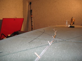
I then micro’d in the foam plugs for the main gear bolt holes and the Nylaflow tubing into the rudder cable conduit channel along with the 2 brass tube sleeves. Again, I held the conduit in place with toothpicks while the micro cured.
After 2-3 hours, I removed the toothpicks that were imbedded into the micro (much easier BTW when the micro hasn’t fully cured!)
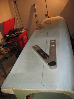
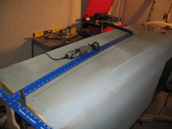
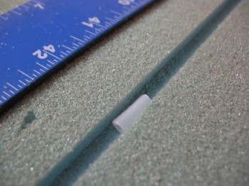
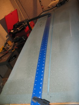
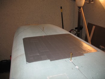
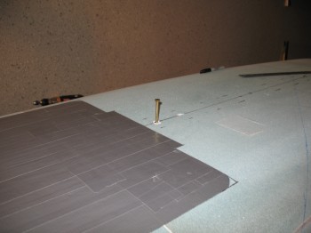
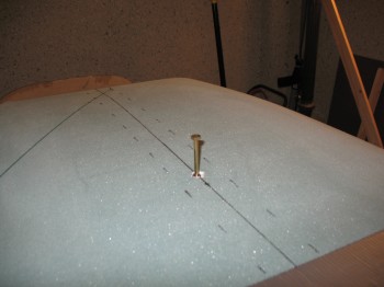
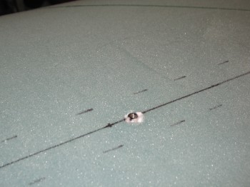
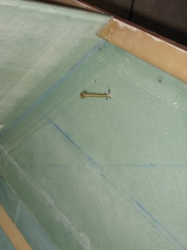
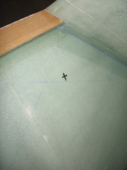
Then in preparation for yet another mod, I drilled two holes along the bottom fuselage’s centerline, one fore and one aft of the landing brake, to install two threaded aluminum inserts so that I can mount a long, straight bar that will denote my extended centerline when I build my nose and my strakes, and also when I rig my wings and canard. I also threw one of these lightweight inserts into the fuselage sidewall, just aft of the upper pilot’s seat, to provide for a future threaded sidewall mounting hard point.
•••
4 June 2012 — Today I removed the few remaining toothpicks holding the Nylaflow conduit in place. I trimmed the rudder cable channel of any excess & high micro, and then razor cut any excess foam & micro from the main gear extrusion bolt hole plugs. I then sanded the newly emplaced foam/micro bolt hole covers to finish.
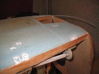
On the fuselage bottom I used 2 long AN3 (3/16″) bolts threaded into 2 aluminum threaded inserts (Note: These inserts, or ‘bungs’, are also used to mount the bomb-looking baggage pods to the wings.) that will be mounted into the fuselage foam on the underside fuselage centerline. FYI – The Cozy Girrrls sell these threaded aluminum inserts.
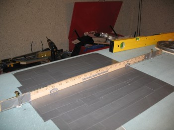
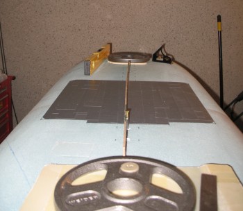
I then taped the 2 bolts to a yardstick and then micro’d the 2 threaded aluminum inserts into two holes that I had already placed and drilled in the fuselage’s centerline—one fore and one aft of the landing brake. Since there is a slight curve to the fuselage from fore to aft, I weighed down each end of the yard stick and then rechecked that the bolts were 90° to the fuselage. Now “90° to the fuselage” with a slight curve means that they are not exactly parallel: the curve will create about a 0.5° to 2° offset between the bolts. This offset will be manageable and the impact negligible.
As I was preparing for the installation of the bottom centerline threaded inserts, I also prepped the right inside fuselage wall so that I could have a threaded hard point mounted inside the fuselage wall for mounting a rear seat component, mounting tab, etc. This is located just behind the front pilot’s seat on the right side:
•••
5 June 2012 — Before it got too late at night (that noise ordinance thing again!) I started out the evening by cutting 4 pieces of 1/4″ Finnish Birch plywood for the hard points that will be glassed into each side of the interior fuselage corners where the seatbelt brackets will mount. There is a 7-ply BID layup that goes over these 1/4″ ply hard points, so the seatbelt mounts are designed impressively robust & strong. Since the pads that will be made up of the 7-ply BID aren’t that large, I scrounged together some scrap BID to throw into some “Poor Man’s” pre-preg set-ups. Once I got the set-ups ready, I set them aside to use in the next few days. (Sorry, no pics just yet)
I then checked and cleaned up the 3 threaded bungs: 2 BDCL and 1 interior R-side aft cockpit. I double-checked the fit & finish of the bolt going into the Right side fuselage wall insert and it fit great and threaded in/out fine.
I marked and drilled out a foam hole on the Left side to mount an insert on the interior fuselage wall opposite the one on the right.
I whipped up some micro and micro’d in the Left fuselage wall threaded insert (from the outside of the fuselage).
Since I had a fair amount of micro left over, I also filled in some fairly deep gouges in various places on the fuselage.
•••
6 June 2012 — Today I have at least one more controversial mod to make. I’ve been discussing these with a number of people, so here goes.
First, I’m planning on running my brake lines down the outside of the fuselage, imbedded just under the skin, like I did my rudder cable conduits. The only difference is that the brake lines would A) run along the bottom of the fuselage, one on each side of the landing brake, and B) be encased in Nylaflow for their entire journey through the length of the fuselage. Since I’m running 1/8″ aluminum brake lines, the ability to withstand pressure is high and I have a security blanket, almost literally, with the Nylaflow. [Note: I was originally going to go with Dick Rutan’s idea of stainless steel: but too hard to bend & also just found out the wall thickness is too great—so it won’t allow enough brake fluid to travel back & forth enough to recharge the brakes].
I’ve traced this out, and reviewed the mechanical layout a dozen times, as well as assessed the pros & cons, and I like the idea a lot. It means by the time I’m done skinning the outside of the fuselage, I’ll have both my rudder cable conduit and my brake lines “pre-run” cleanly without having to get into the inner bowels of the fuselage. Plus, I’ll essentially have one long brake line run on each side from the rudder/brake pedal (Point A) to the brake assembly (Point B) with no connectors in between (unless I choose to).
From my Bomb Squad days I like to worse-case-scenario things. I think any brake fluid leaks will be mitigated greatly in this dual-layered system. If something does go wrong, then the answer to peoples’ “what about maintenance?” question means that worse case I would snip the end of each line and run the brake lines per plans inside the cockpit and suffer a small weight penalty. In fact, my first act today was planning out & drawing the runs for the brake lines. Ok, enough on internal brake lines.
The next mod is a result of one of those head-scratching moments all of us builders have reading the plans. I didn’t understand why we skin the fuselage, and then turn around and drill holes through the skin to mount the seatbelt brackets. I read, looked at the diagrams, reread the plans and it just didn’t seem right to me. I Googled it, and then hit the blogs and the phones. I talked to my building mentor, Dale Martin, and others and still didn’t have a good feel for why the build sequence between the seatbelt bracket mounting and skinning seemed reversed (for the record, Dale suggested I follow the plans).
I finally made a command decision. Not wanting to drill through perfectly good glassed fuselage skin, I decided to mount my seatbelt brackets before I glassed the fuselage. Thus, below you will see exactly that: the start of my seatbelt mounting.
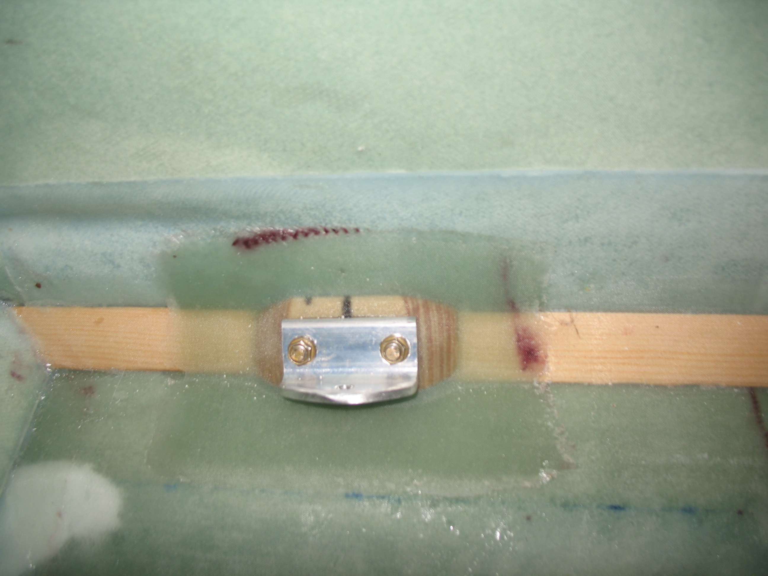
First, I finished cutting & sanding the 1/4″ plywood seatbelt hard points and then mocked them up for install. They looked good so I floxed them in place. I then wetted out the 7-ply BID “Poor Man’s” pre-preg setups that I had made up the night before, and then respectively glassed in the 4 seatbelt hardpoints with 7 plies of BID on each one. I then covered these 7-ply layups with peel ply and overlapped it onto the surrounding glass to get a nice, smooth transition. All the layups looked good, so I left them to cure.
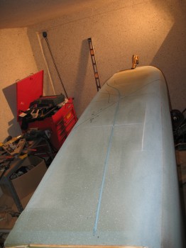
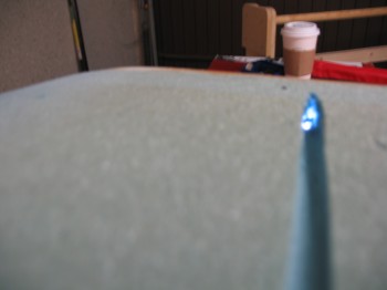
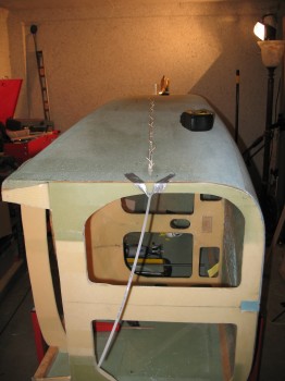
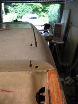
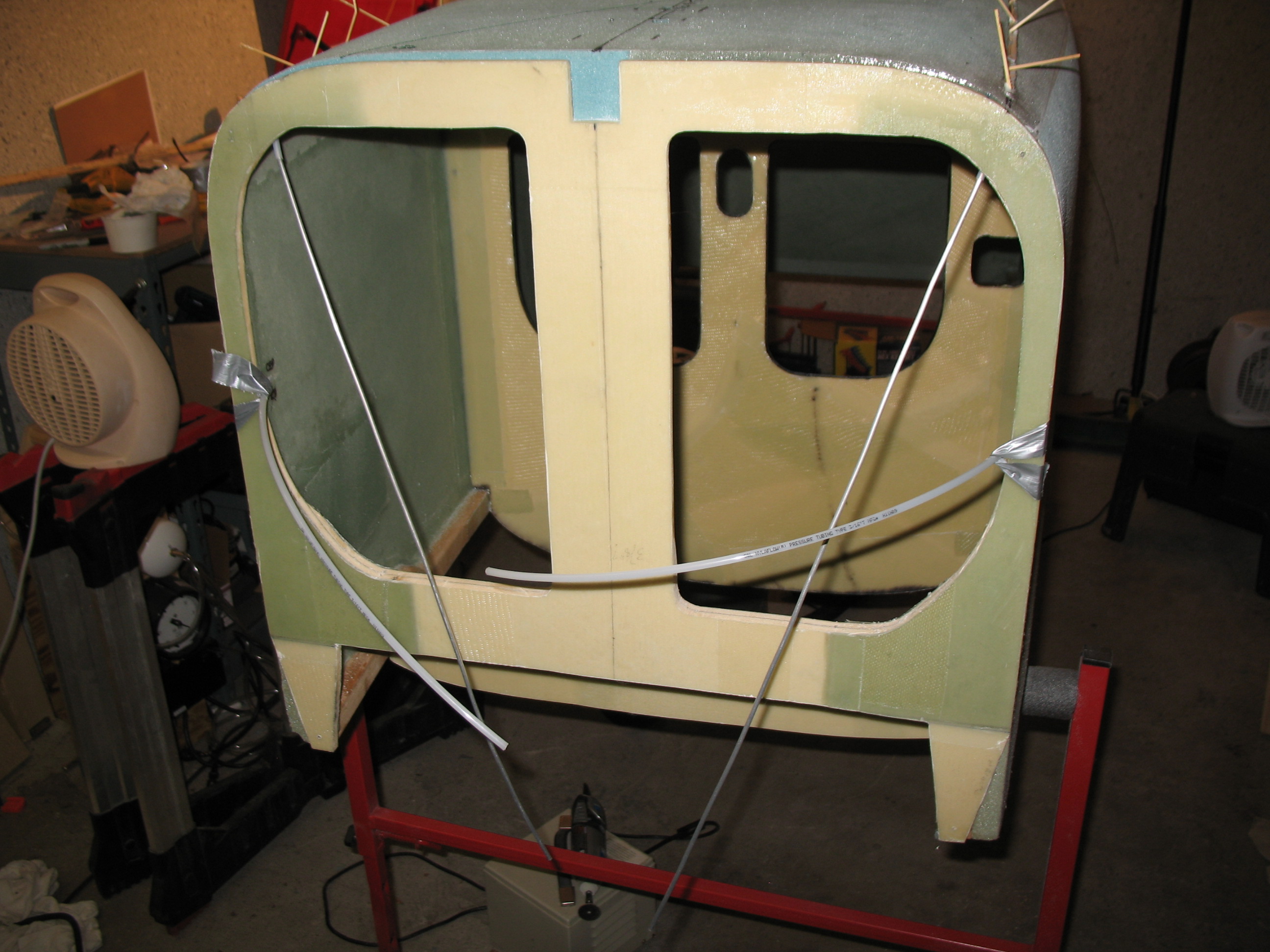
The pic below just shows the front end of the fuselage with the new rudder cable conduits coming out the front. I just gave my fuselage fangs! How cool is that?!
 Finally, to wrap up some of the tasks over the last couple of days: when I attempted to drill the final hole for the fuselage Left-sidewall thread insert, the drill must have just barely caught the soft aluminum, because when I inserted the bolt it caught and I put just enough force on it to strip it out. So I drilled it out, will reinsert another one, and will redouble my efforts to be more vigilant and careful!
•••
7 June 2012 — Today was a non-building day. I focused on getting a bunch of items that I received in an Aircraft Spruce shipment inventoried, organized and stored, along with some other items that needed the same.
I try not to go too long in-between entering everything I order into my tracking spreadsheet. In the spreadsheet I track every item that I’ve bought, and I have a list of every item I plan to buy & schedule of what timeframe I’m going to buy it (that’s the project manager in me coming out!). So, in my spreadsheet I list everything under 6 main categories:
- Bought
- Phase I – Materials (required for building: wood, metal, foam, etc)
- Phase II – Parts (metal aircraft parts, hinges, etc)
- Phase III – Major Components/Finish (electrical, engine, prop, avionics, paint, etc)
- Phase IV – Post Build Items (AC Cover, Anti-static spray, gust locks, etc)
- Tools
After my inventory spree, I drew out my initial plans for lo-vaccing the armrests and rollover assembly.
I also checked the 7-ply BID layups on the seatbelt bracket hard points and they looked good so I pulled the peel ply off and called it a night.
•••
8 June 2012 — I drove down to Aircraft Spruce EU in Bretten,Germany, about an hour and a half from my house, to pick up 28′ of 1/8″ 3003-0 aluminum tubing for my brake lines. I also picked up some Alodine, a 3′ hinge and a plastic eyeball vent.
When I returned to the house, I finished the other 3 angled aluminum seatbelt brackets and drilled all the holes to 1/4″.
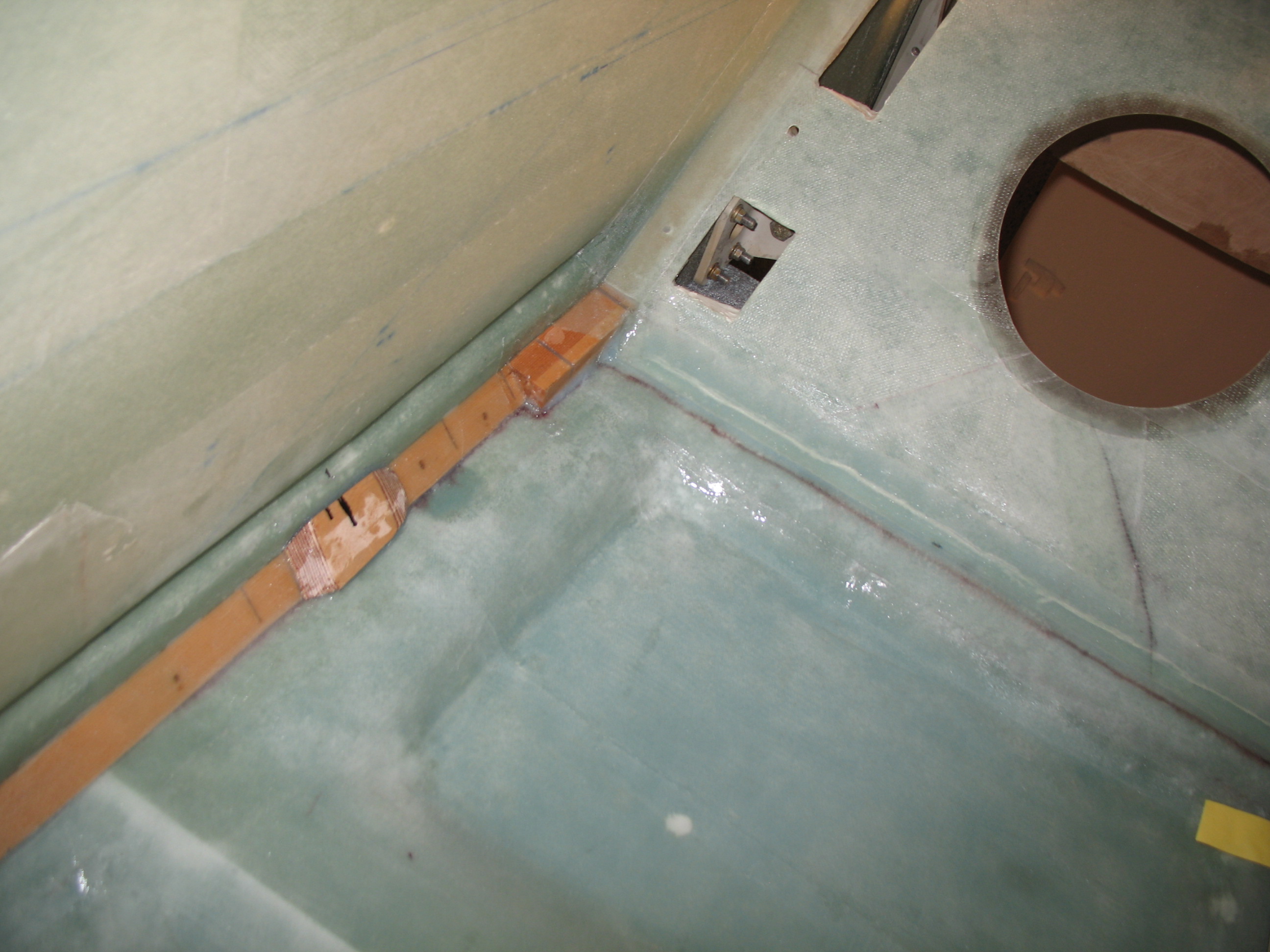
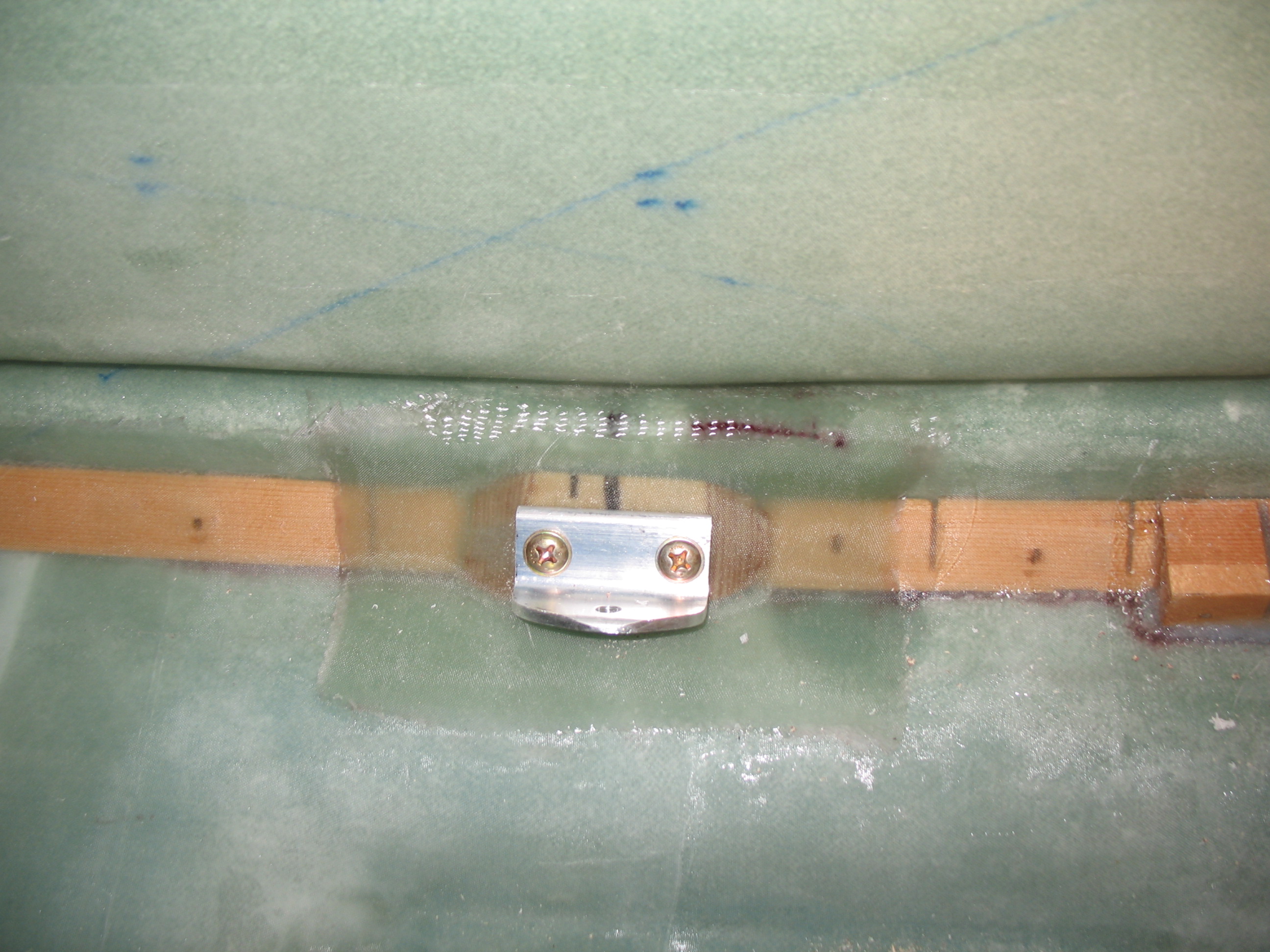
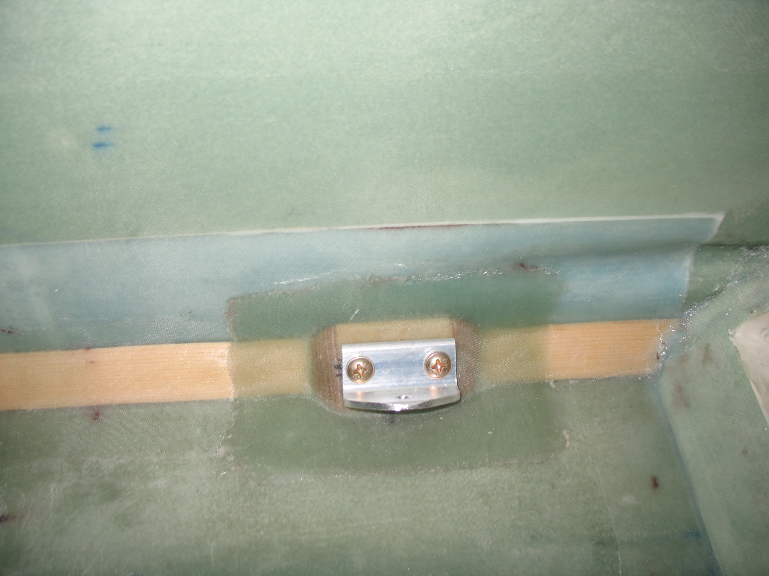
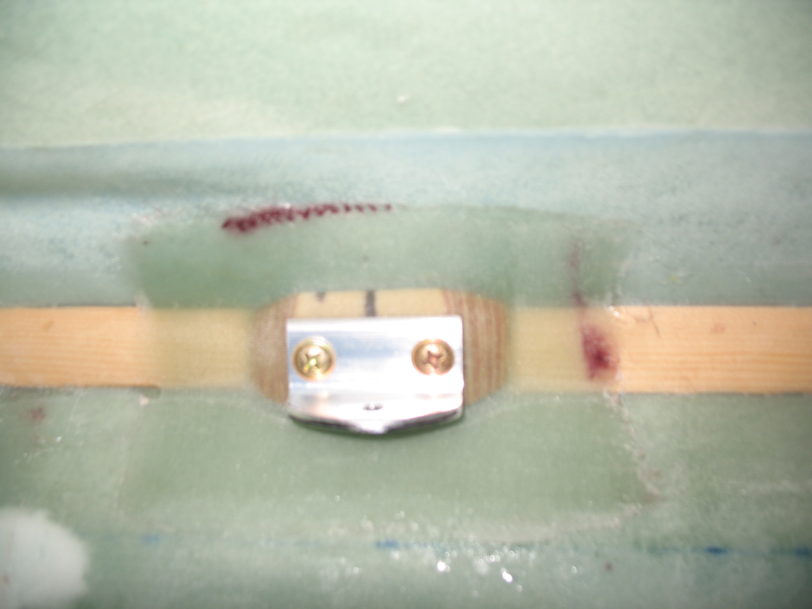
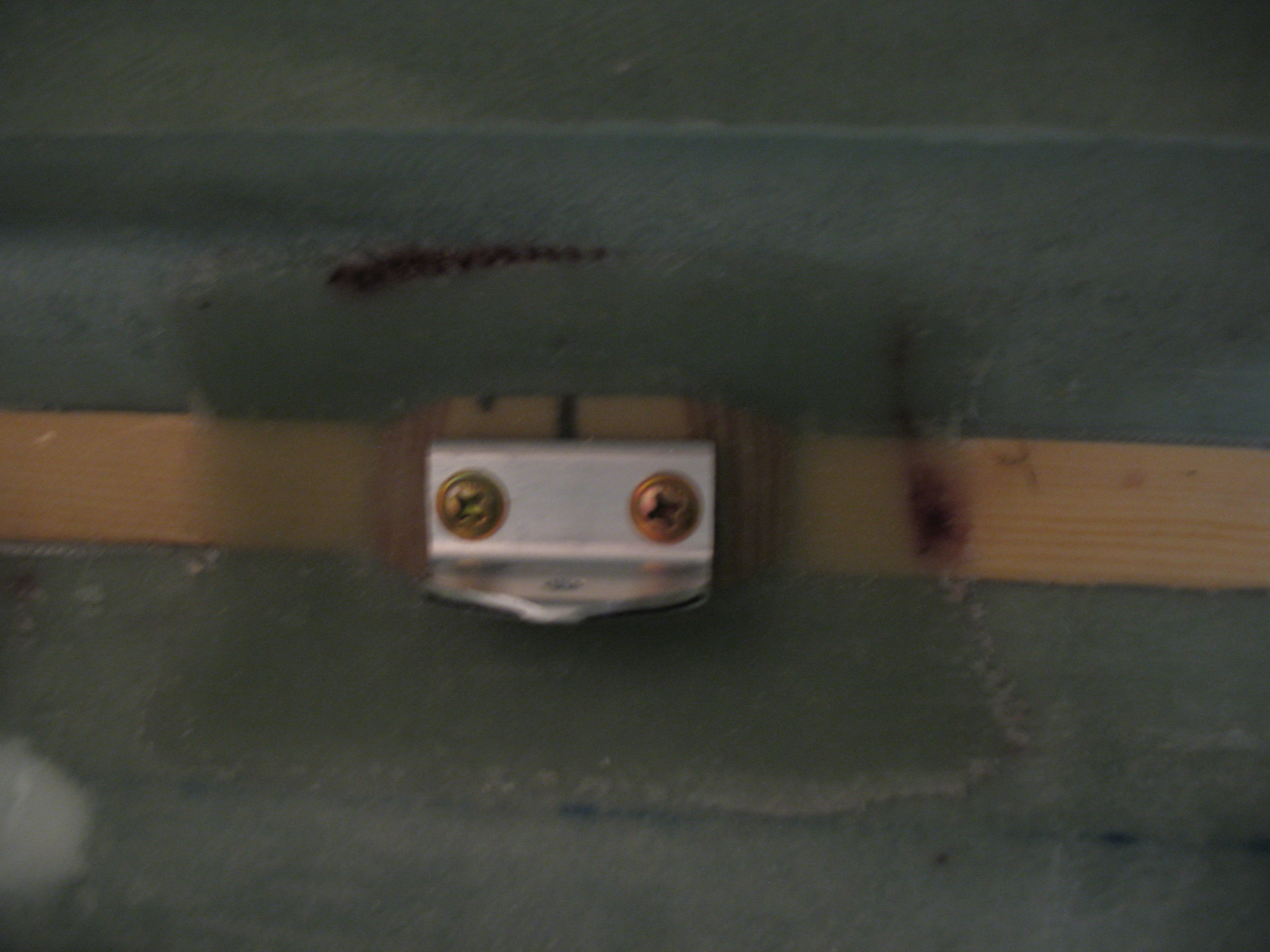
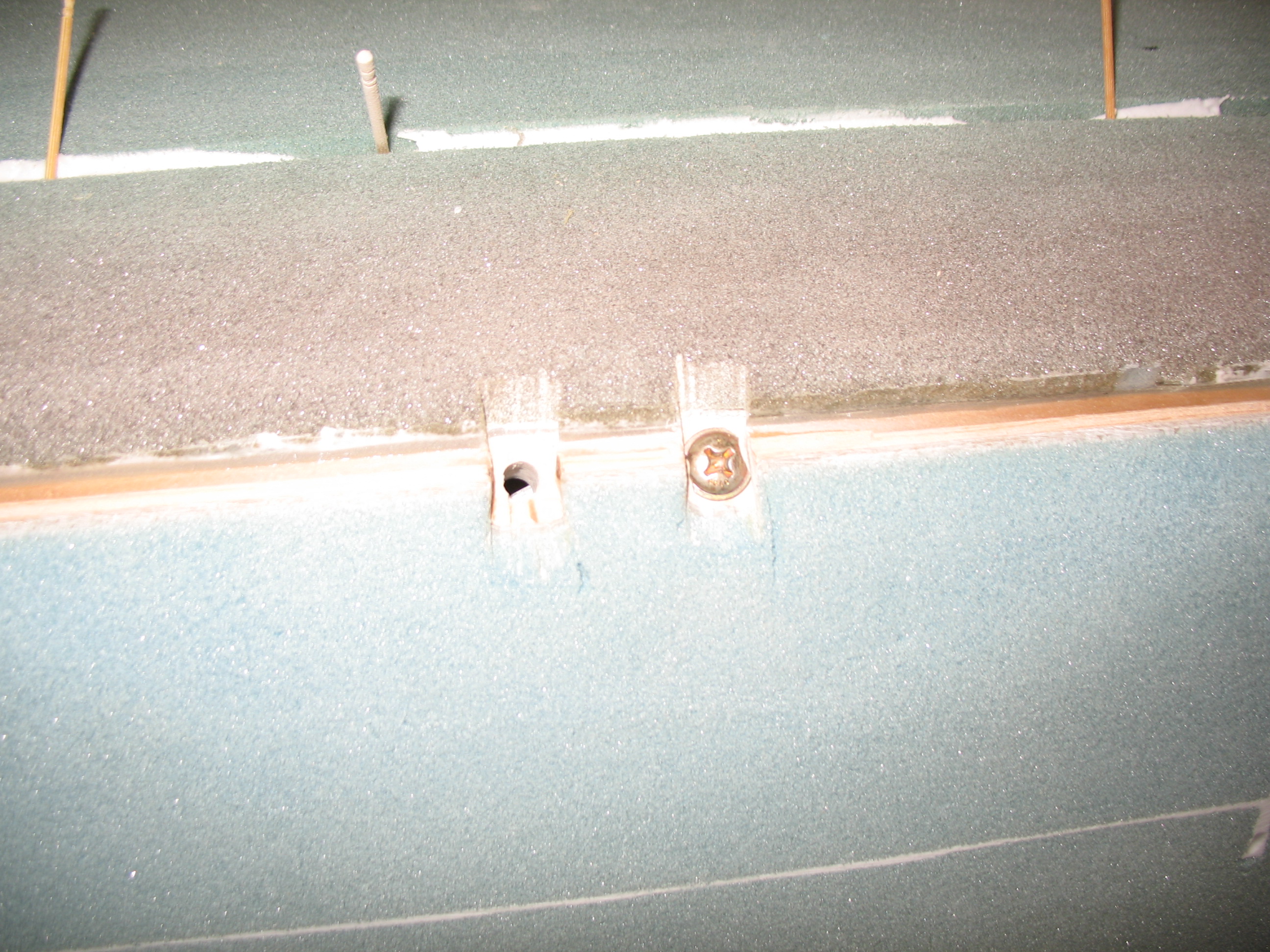
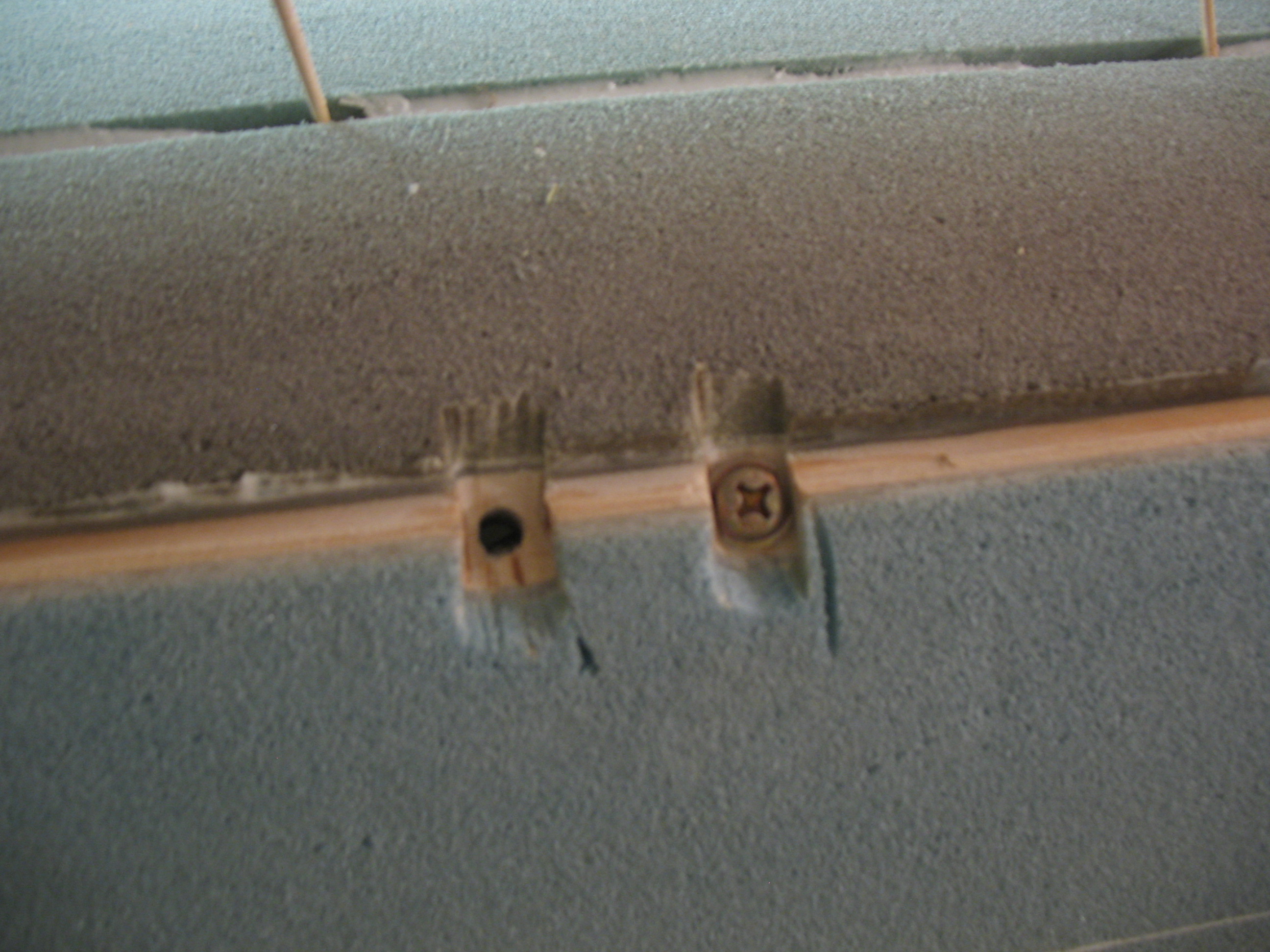
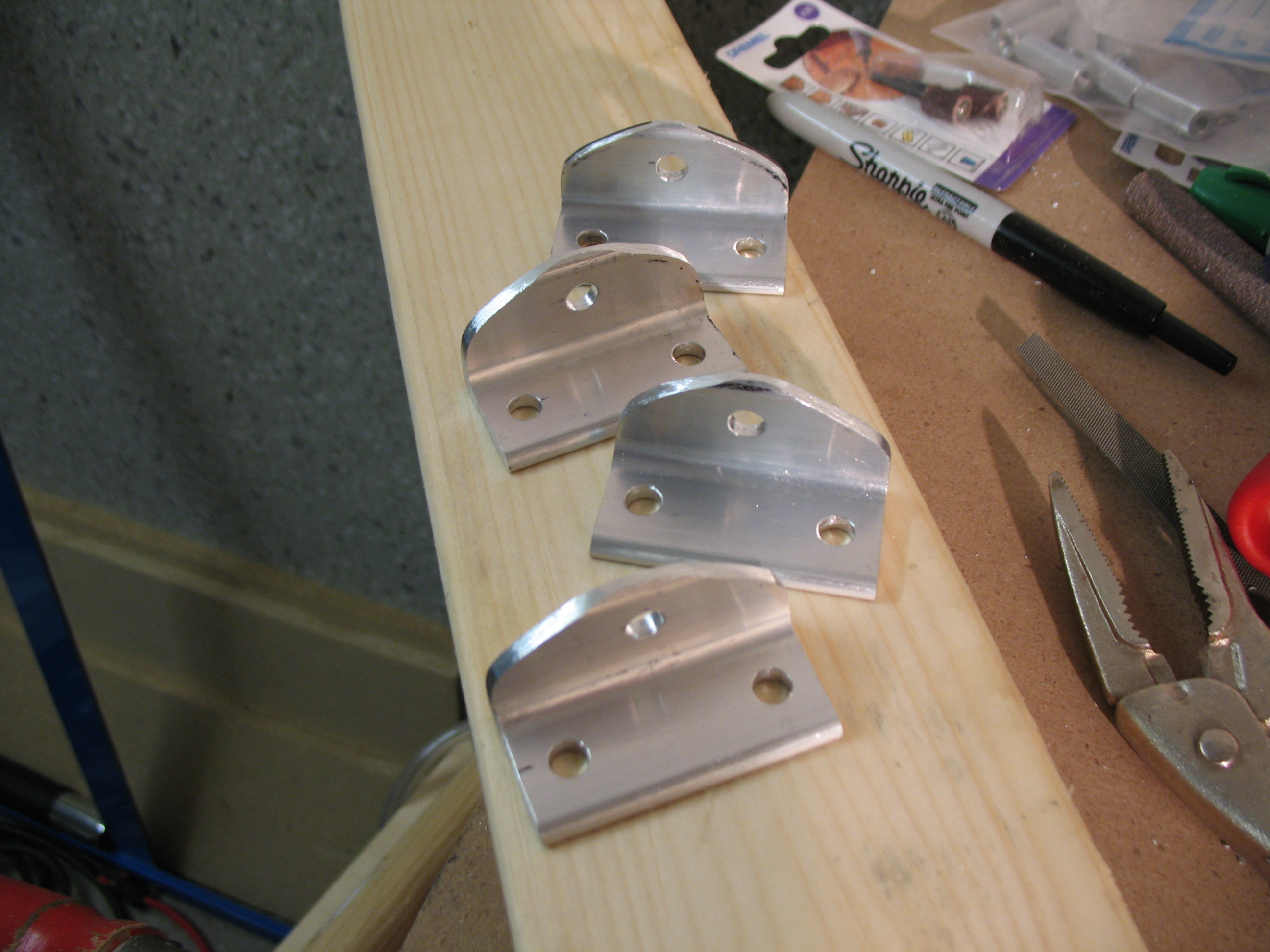 I then lined up and drilled the seatbelt bracket mounting holes into the corners of the fuselage at each of the 4 seatbelt 7-ply BID/1/4″ plywood hard points. Note that in the pics below that the screws are simply inserted into both the seatbelt bracket and hardpoint holes for spacing purposes only, since the screws are installed backwards—as you can tell by the screw head being on the inside of the fuselage vs. the outside.
•••
9 June 2012 — In the same fashion as the rudder cable conduit channels on the sides of the fuselage, I Dremelled a channel down each side of the underside of the fuselage, left & right of the Landing Brake, to run the brake lines internal to the fuselage glass & foam. This is another significant departure from the plans since the brake lines aren’t normally installed until chapter 15, but for all the reasons I spelled out earlier I wanted to get this mod knocked out.
Also, just as a quick mention, the plans still spell out how to install the master brake cylinders on the Firewall in the engine compartment. Ever since Debbie Iwatate’s groundbreaking mod back in 1982’ish to move the master brake cylinders forward to the rudder pedals, it doesn’t seem like there are too many builders who still mount them in back.
After using the Dremel to rout the two channels on the fuselage bottom, I used the #10 long drill bit (again) to drill holes at the front side of the fuselage and at the aft end of the fuselage to bring the brake lines back into the cockpit.

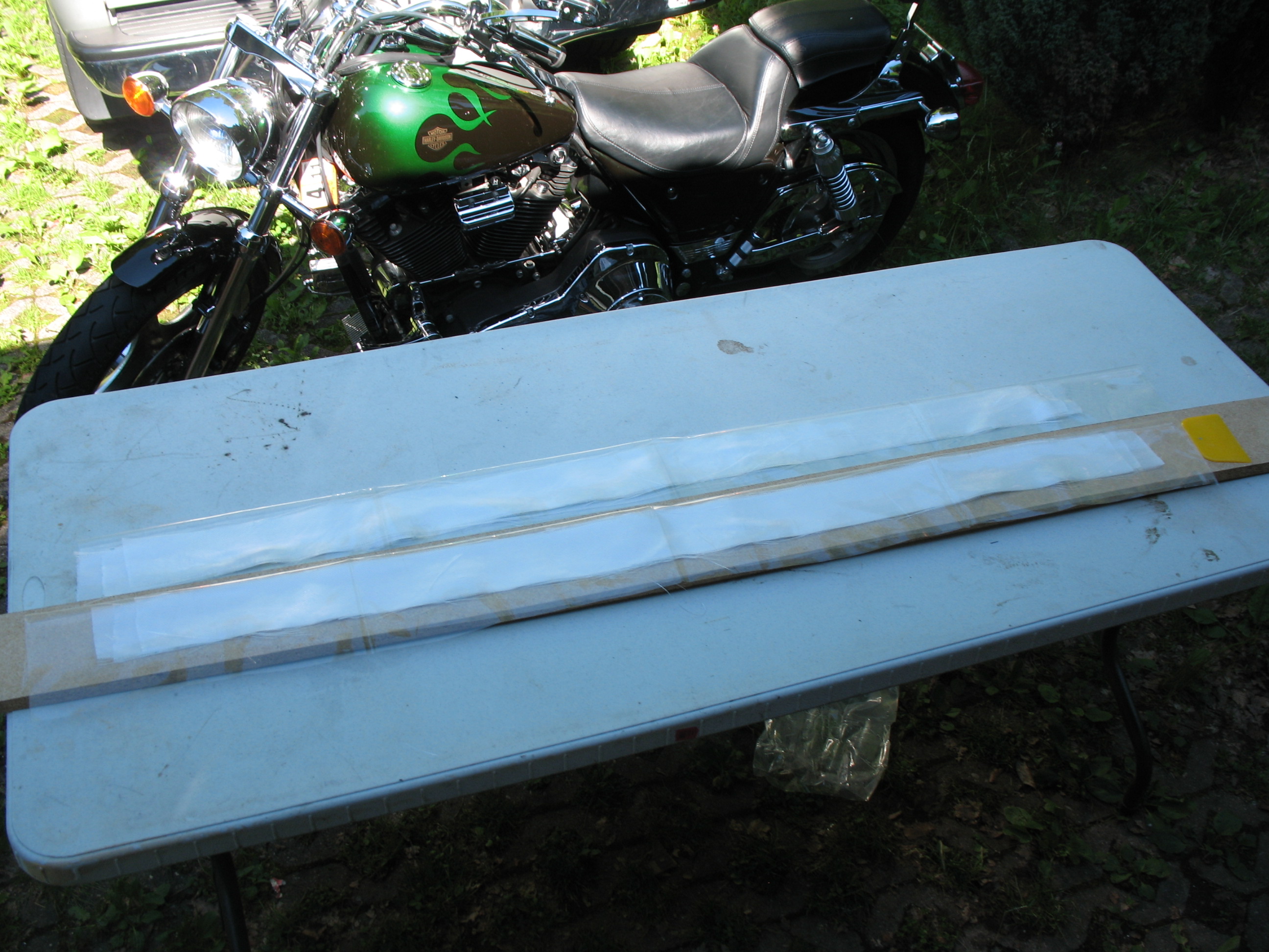
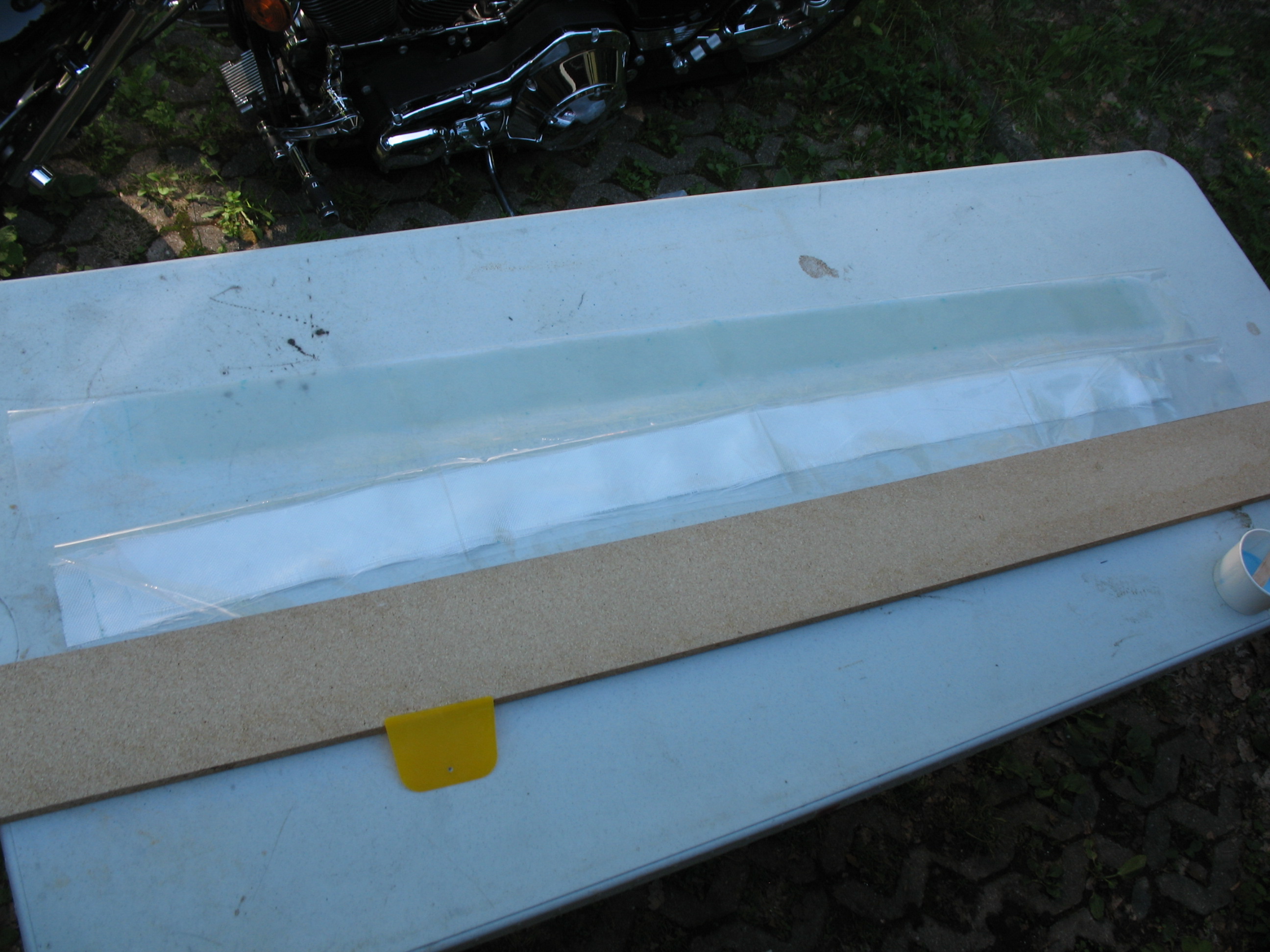
For each side, I took a 14 ft length of 1/8″ 3003-0 Aluminum tubing and inserted it into 88″ of a 3/16″ Nylaflow sleeve. Approximately 22″ of the aluminum tubing will stick out of the front the fuselage on each side.
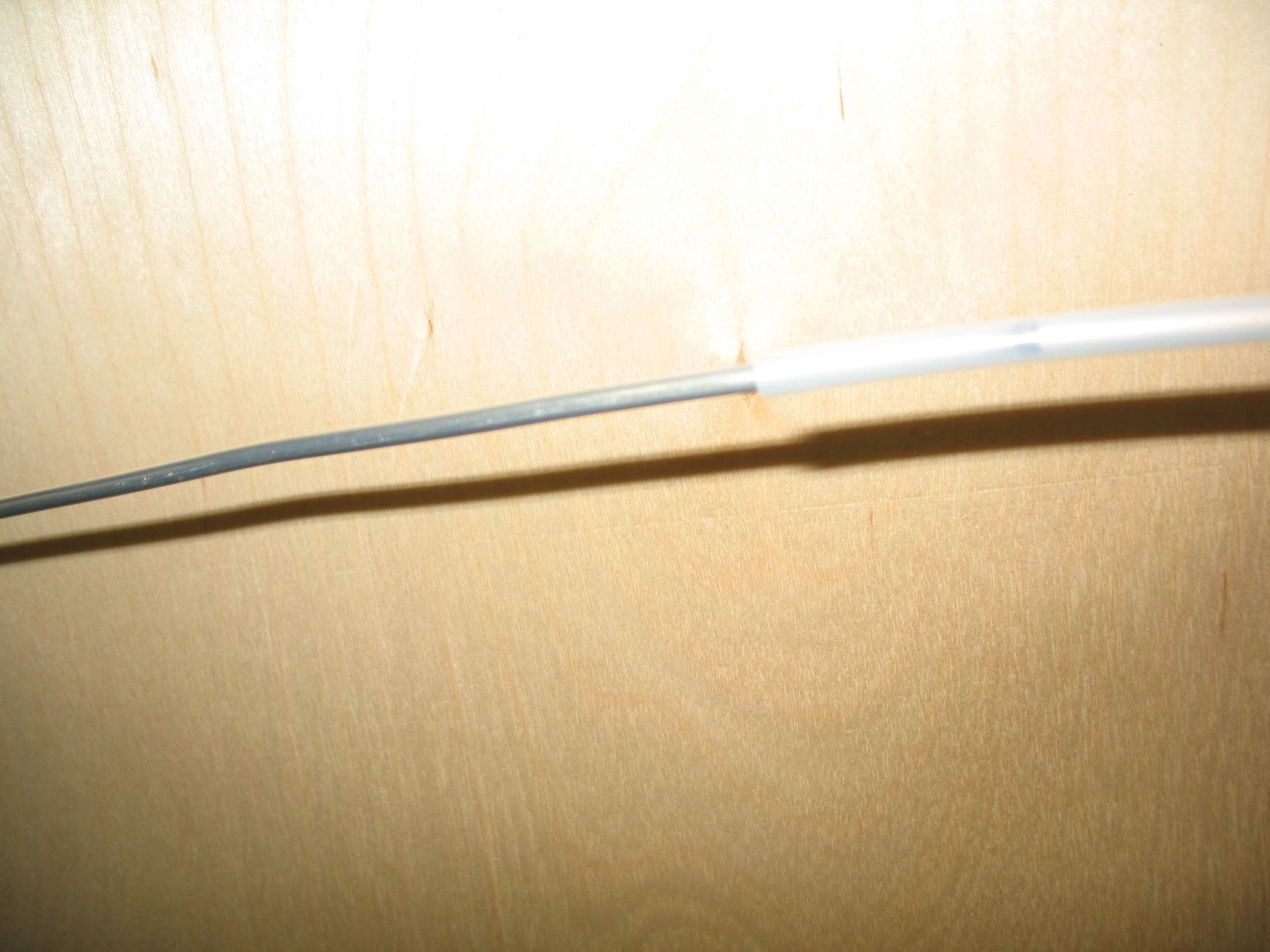
About 1″ of the tubing, on initial entry to the interior fuselage, coming in from the exterior side of the fuselage is covered in Nylaflow as well.
After I got everything set, I micro’d the Nylaflow/aluminum tubing into the channels on both sides of the fuselage and secured the conduits in place with toothpicks.

After about 8 hours I pulled out the toothpicks. The brake line conduits looked good and were secured nicely down into the bottom of each channel.
Chapter 8 Step 6 – Installing Seatbelt Brackets
On to seatbelts! In yet another discussion with Dale Martin, he cautioned me that long before the click-bond era, many a imbedded bolt and screw would either vibrate out of the their flox mooring, or simply break loose when either being tightened or during nut removal. So, how do we ensure this doesn’t happen? Well, we make the screw head NOT round and give it an edge… for flox to grip, and provide a physical stop that prevents the screw head from turning. I ended up following his advice after even further discussing with him and a few other gurus on the affect that “butterflying” the screw heads would have on the strength of the screw. As I suspected, seems that these AN guys are pretty darn stout and it wasn’t a significant limiting factor, so I notched my screw heads in “butterfly” fashion.
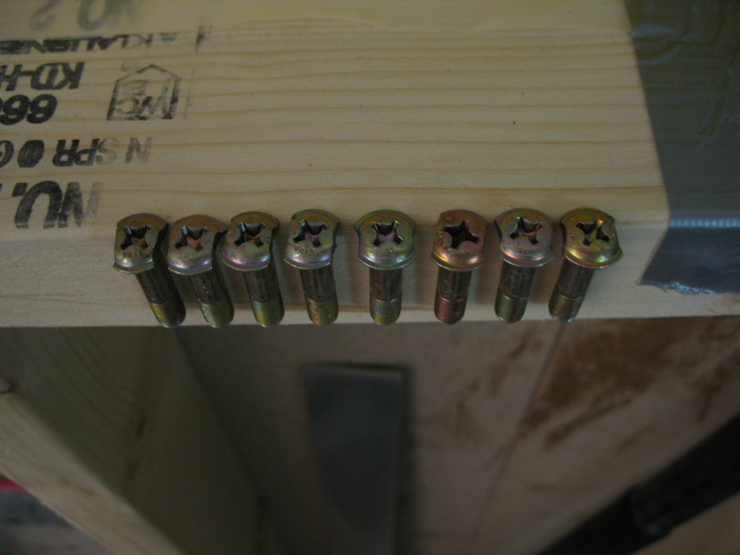
I cut 4 pairs of countersink notches into the outside corners of the fuselage around the screw holes that I had drilled previously from inside the fuselage going out, having used the seatbelt brackets themselves as a template (that’s why each bracket is marked as to where it needs to go exactly since they were initially all hand drilled and have some slight variances in hole locations, drill angles, etc). Besides just making these countersink notches just wide enough for each respective screw head to fit, I also had to make them deep enough so that there would be enough of each screw’s thread coming through the bracket to put a nut onto, and have the requisite 2-minimum threads showing after the nut is mounted.
Finally, I floxed in the seatbelt bracket screws from the outside of the fuselage inward, and put a thin film of flox on the bottom face of the seatbelt brackets. I then bolted on all the seatbelt brackets (my buddy Kevin helped by keeping the screws from spinning on the outside of the fuselage while I installed the nuts from the inside).

•••
10 June 2012 — Today was a prep day to knock out some of the myriad of nit-noy things that need to be completed before the fuselage can be skinned.
So, before I turned the fuselage back upright I rechecked the embedded brake lines. I specifically wanted to make sure the foam/glass conduit exit points were good—they look fine and positioned correctly.
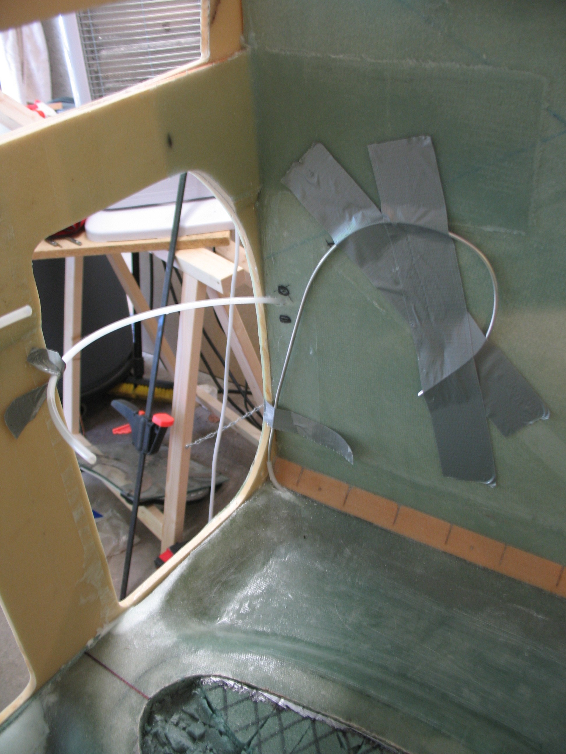
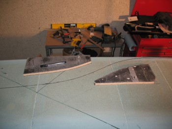
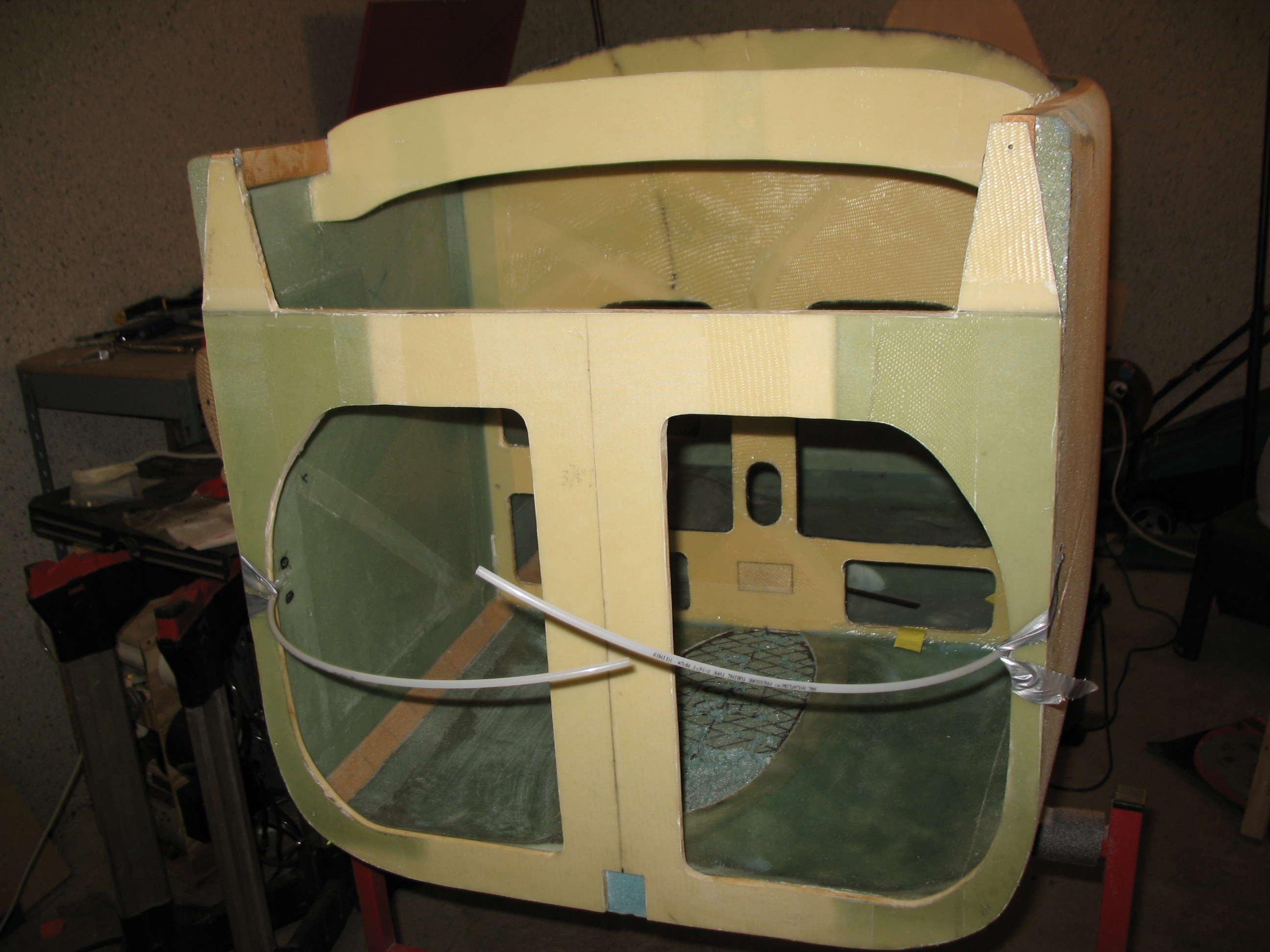
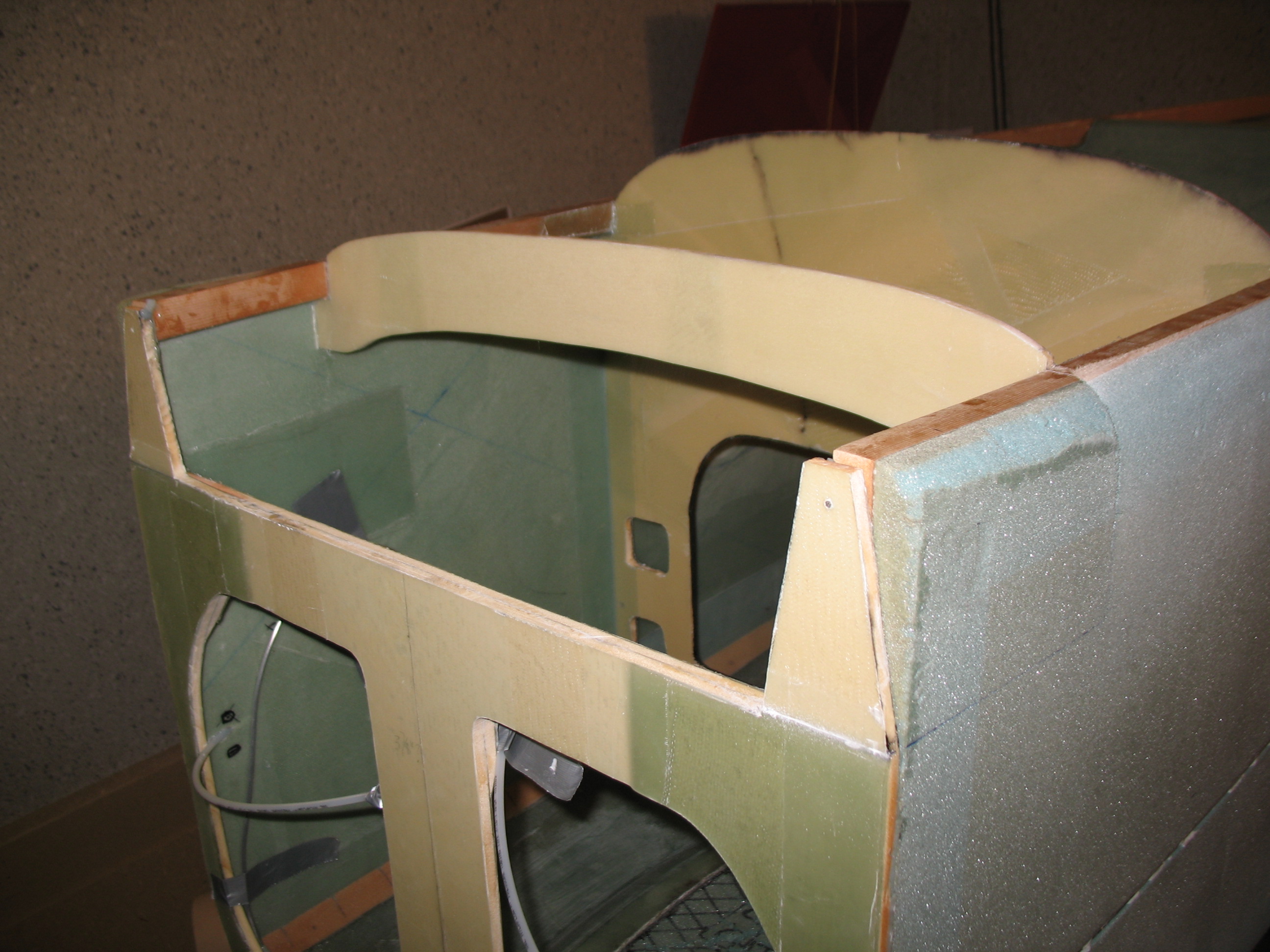
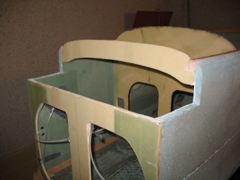
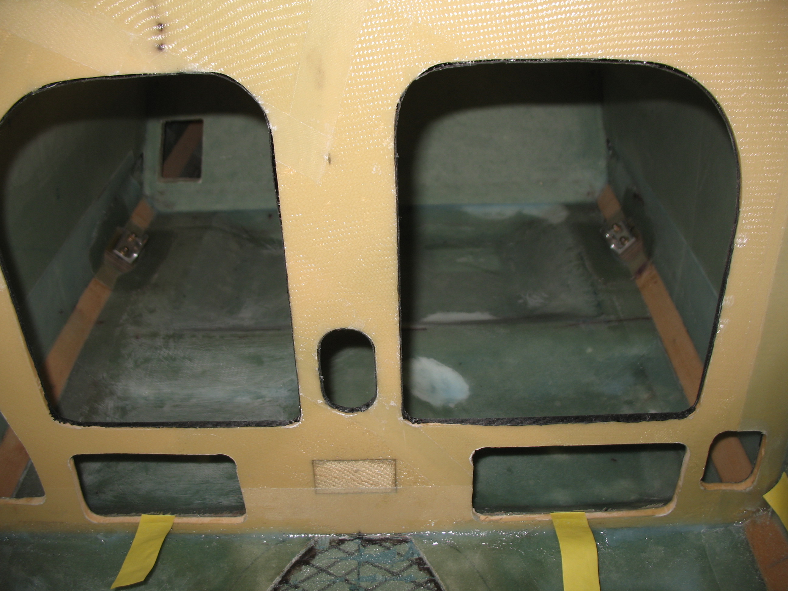
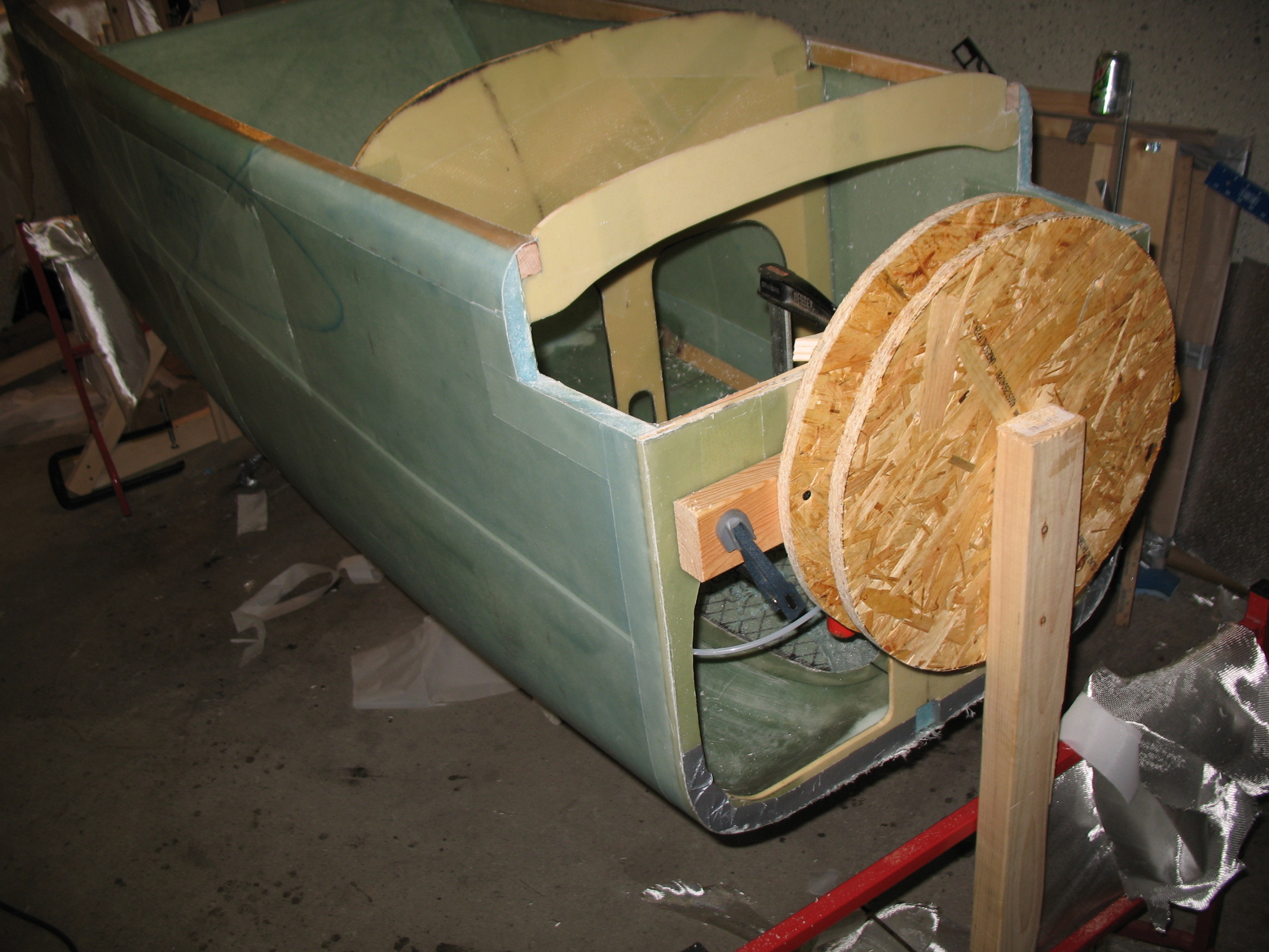
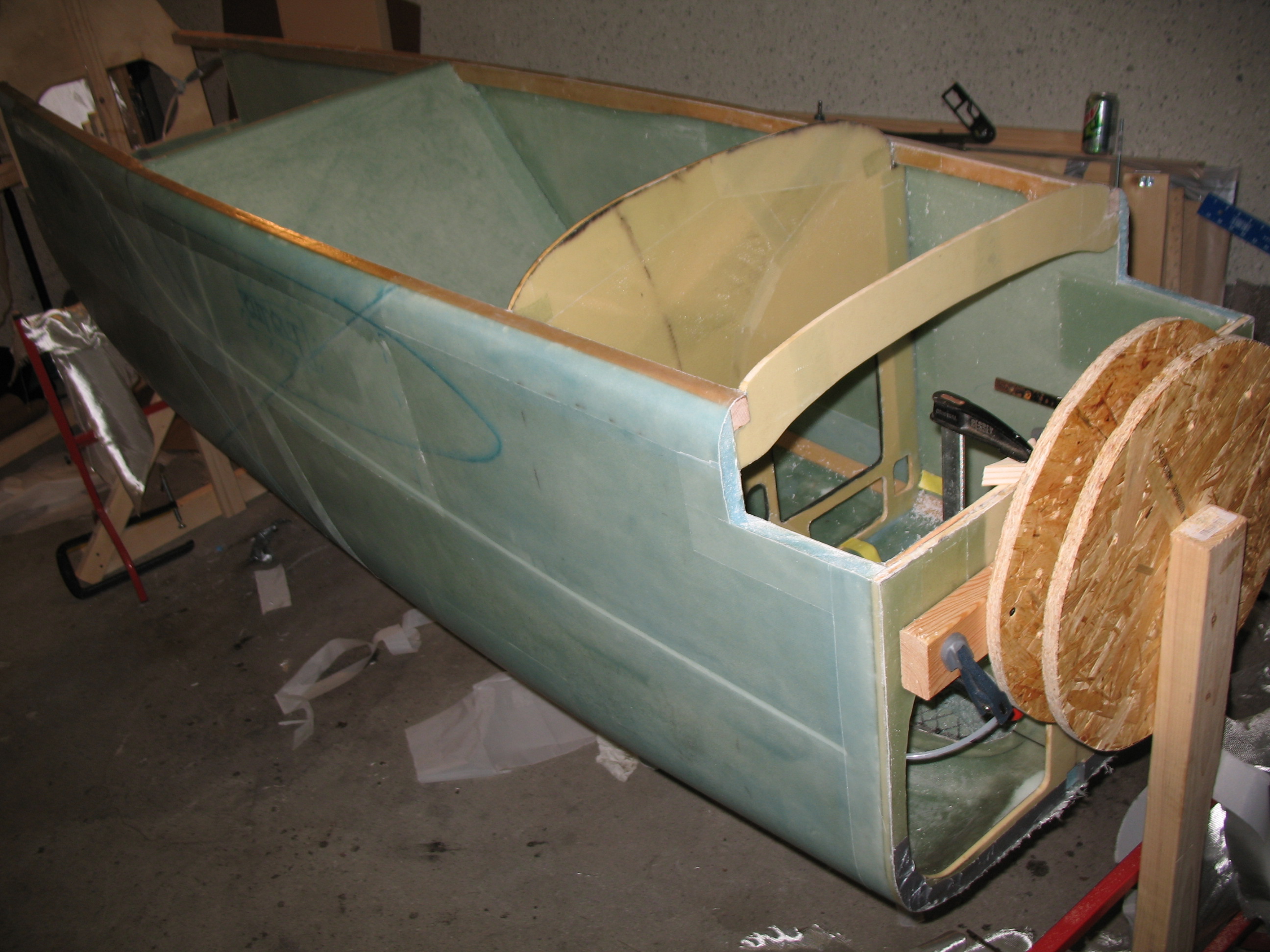
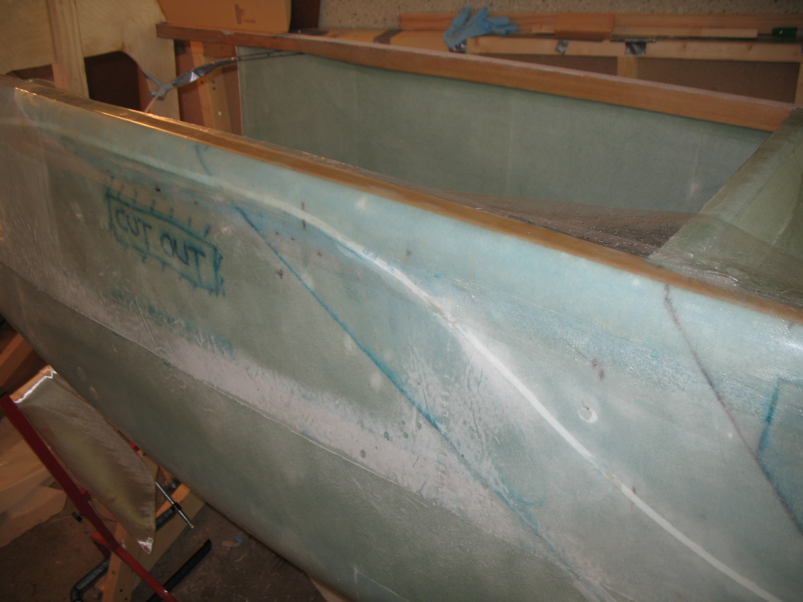
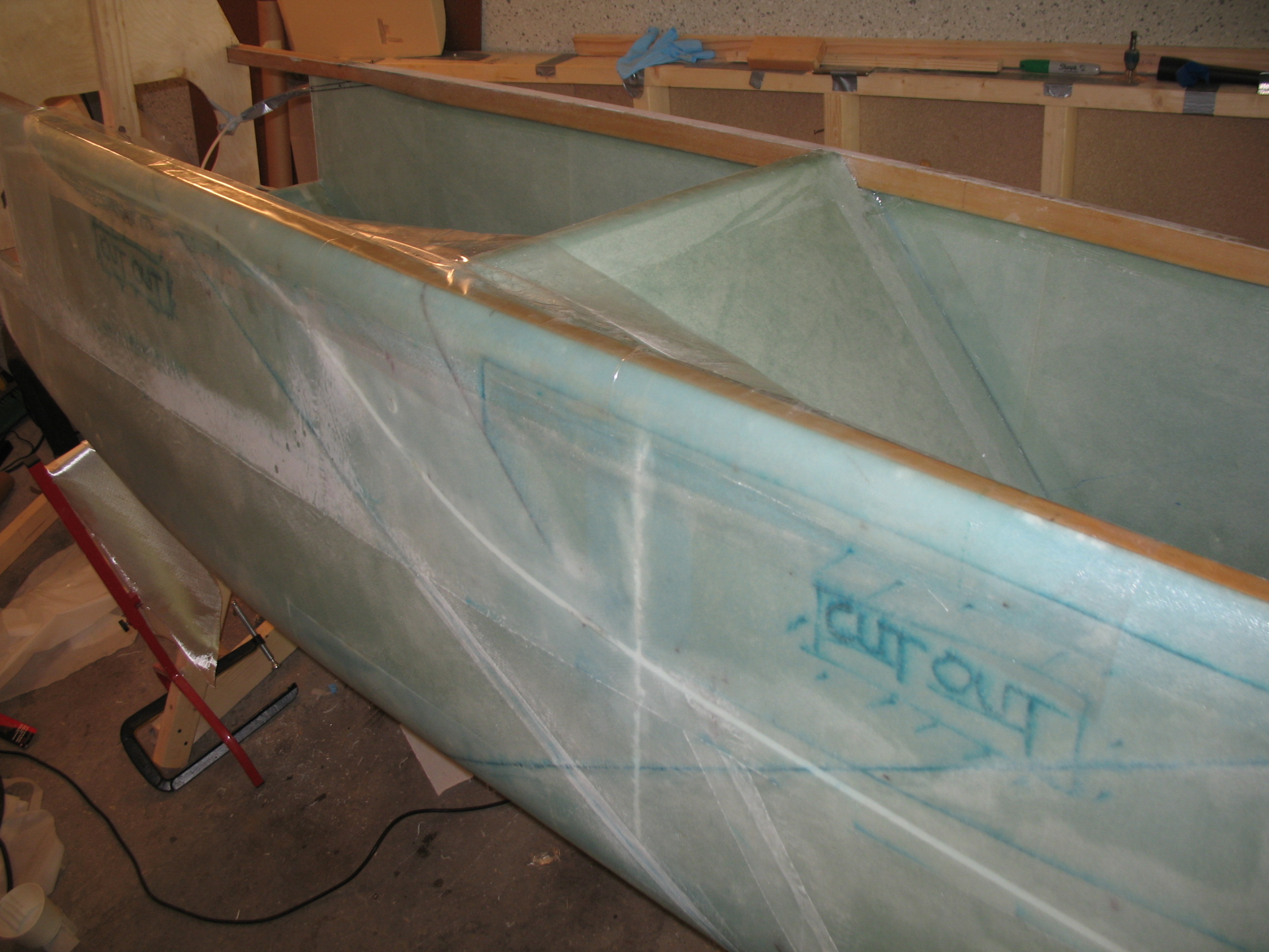
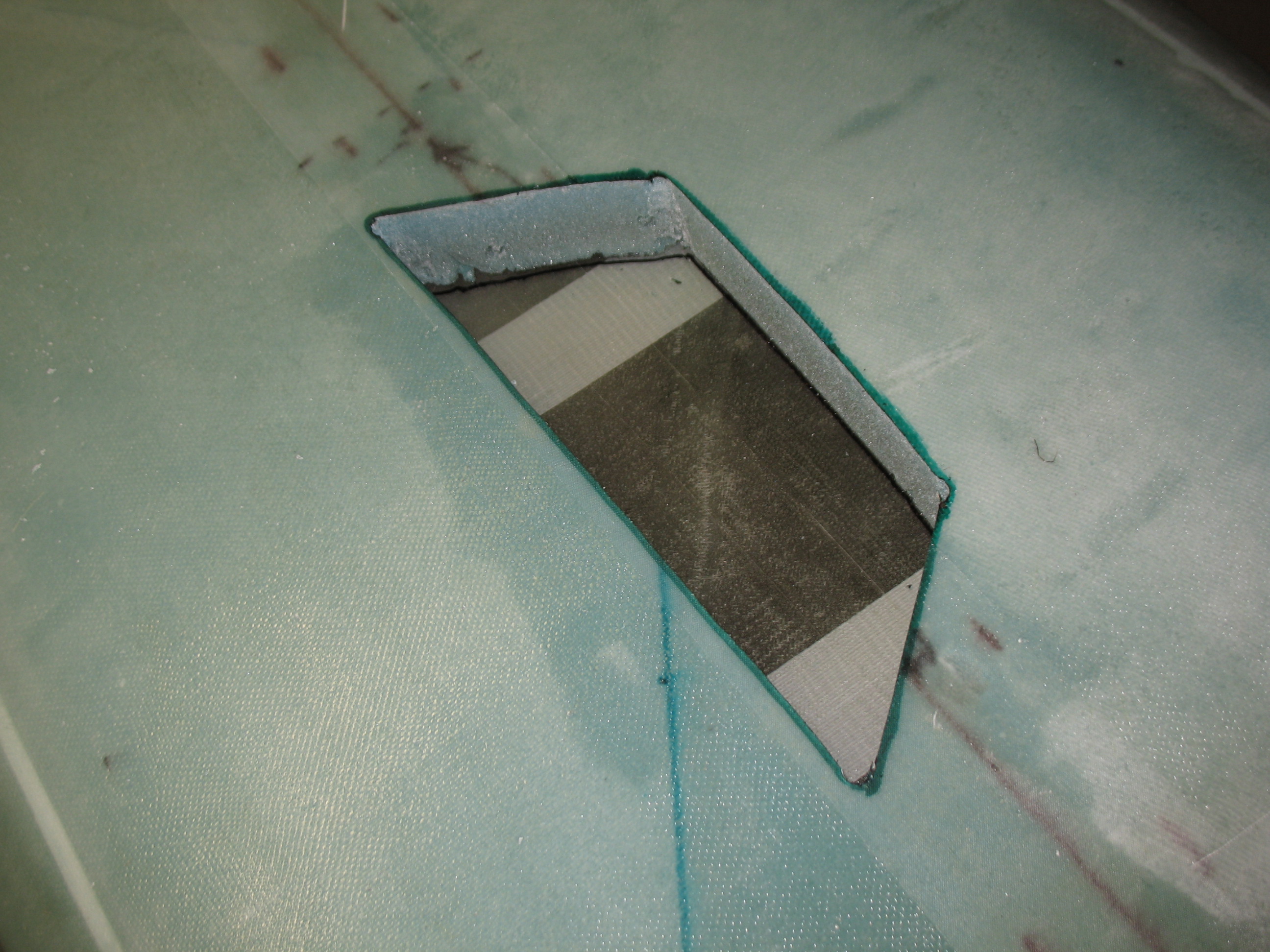
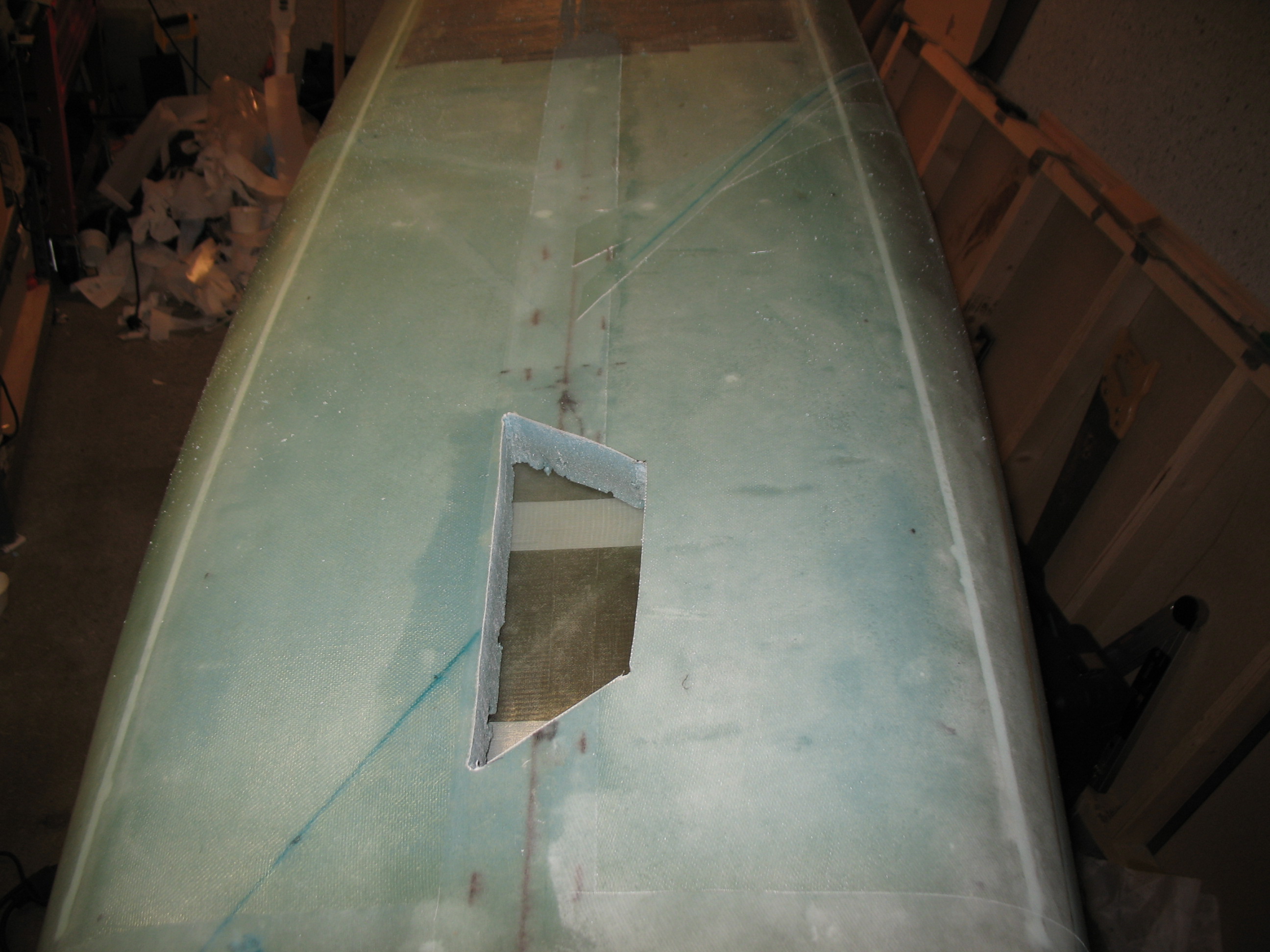
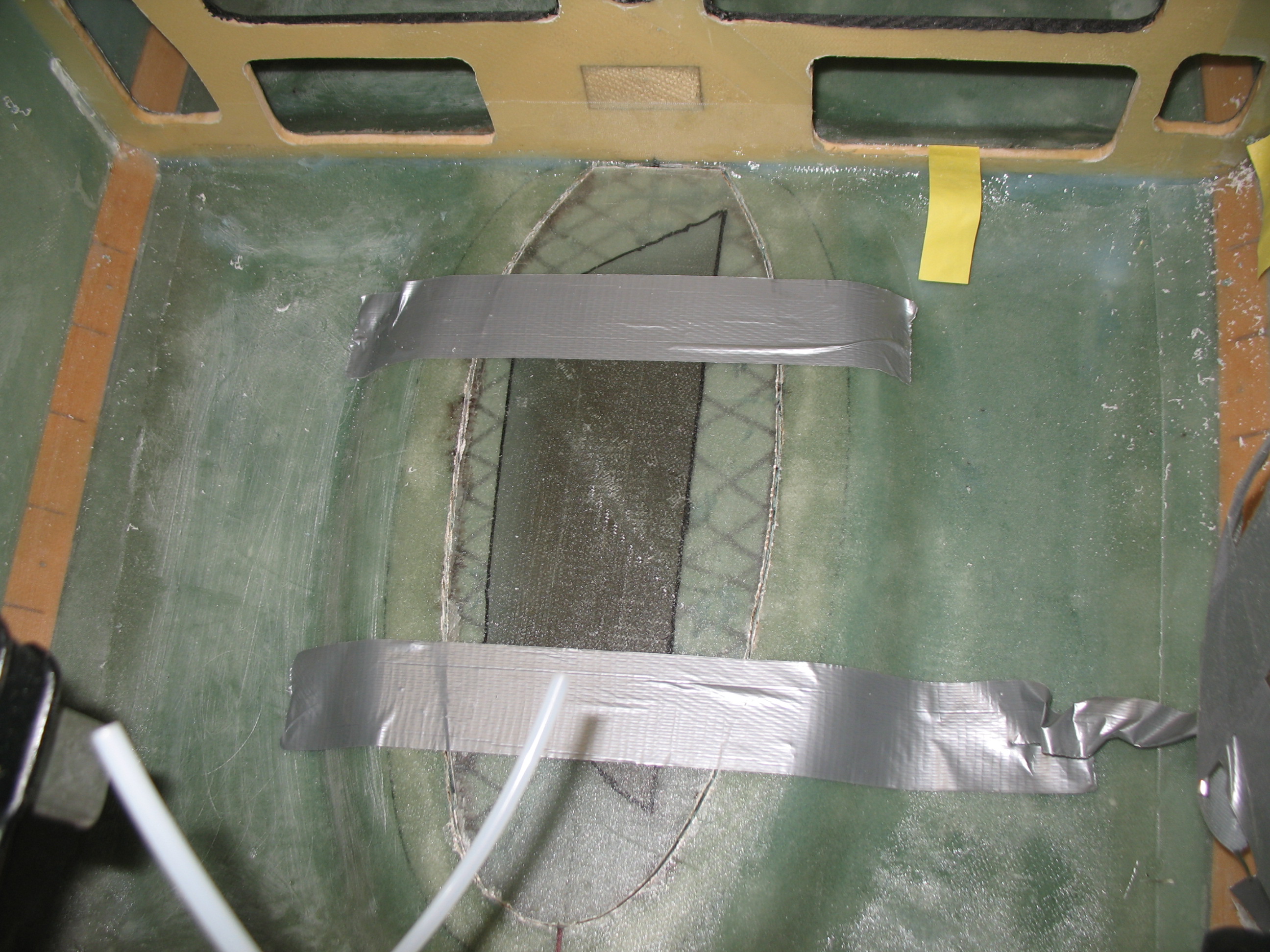
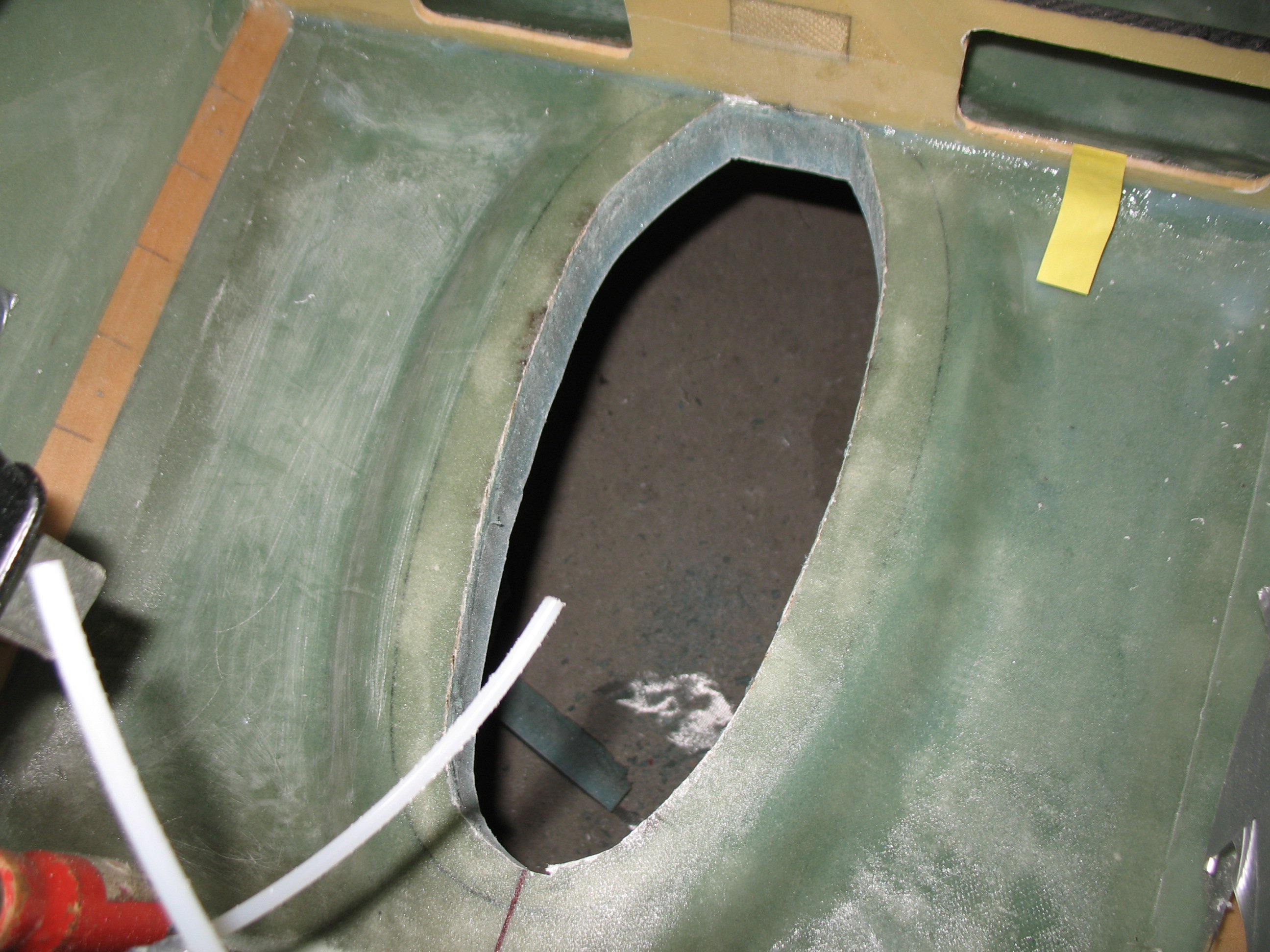
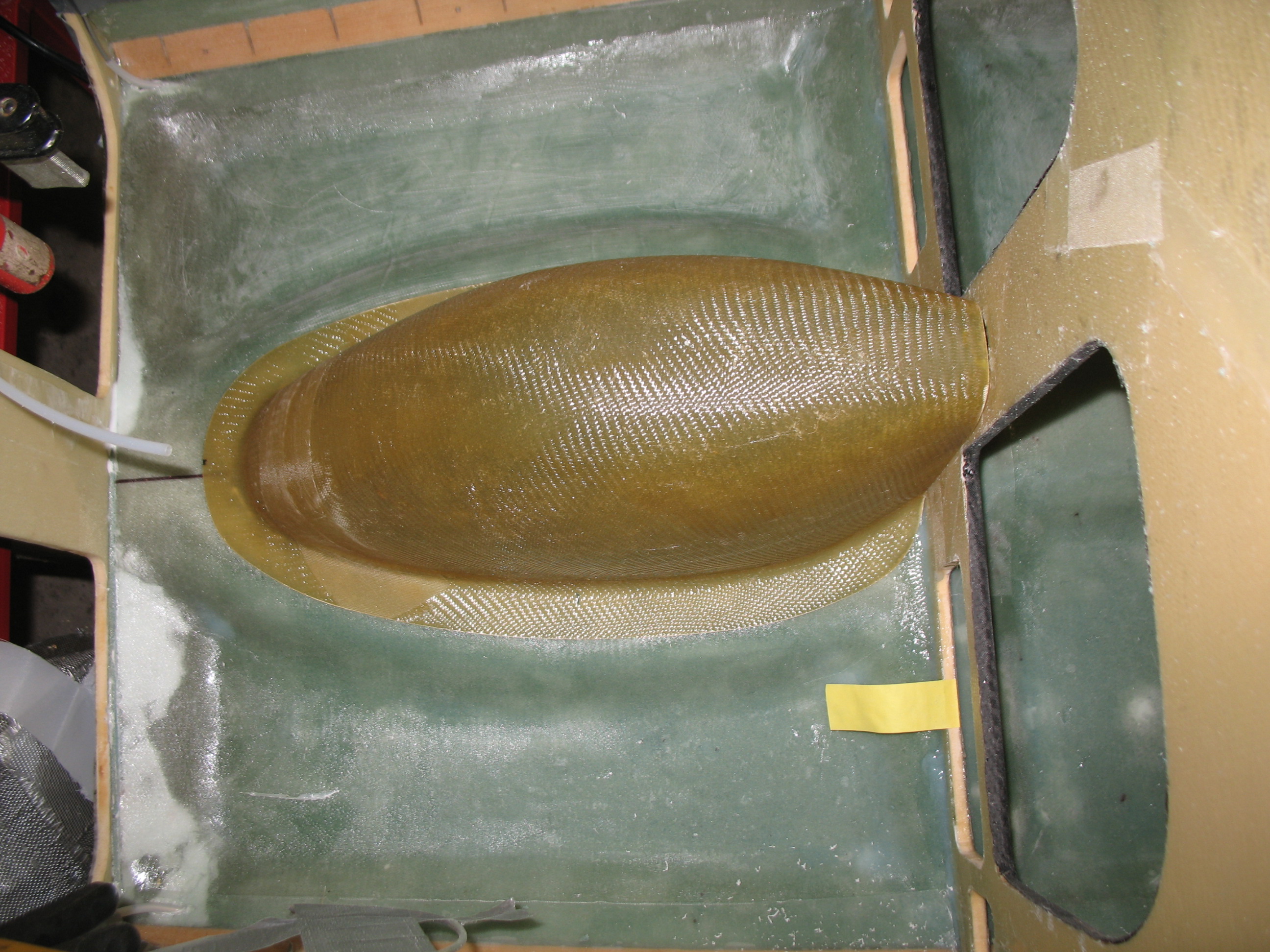
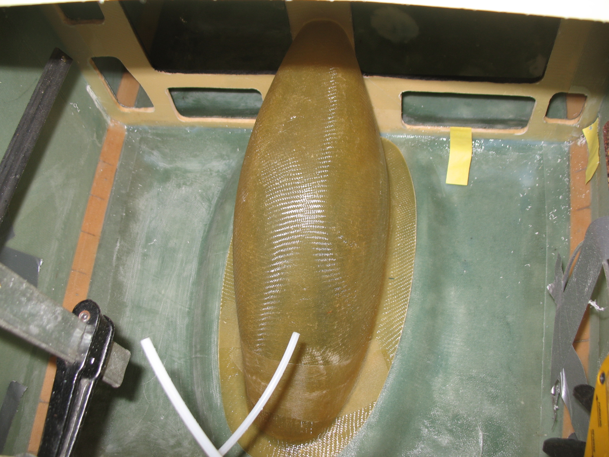
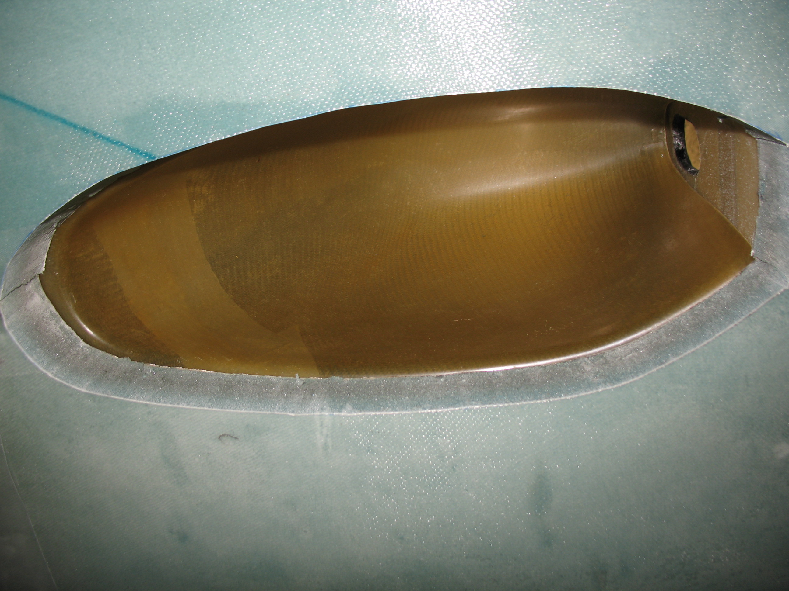
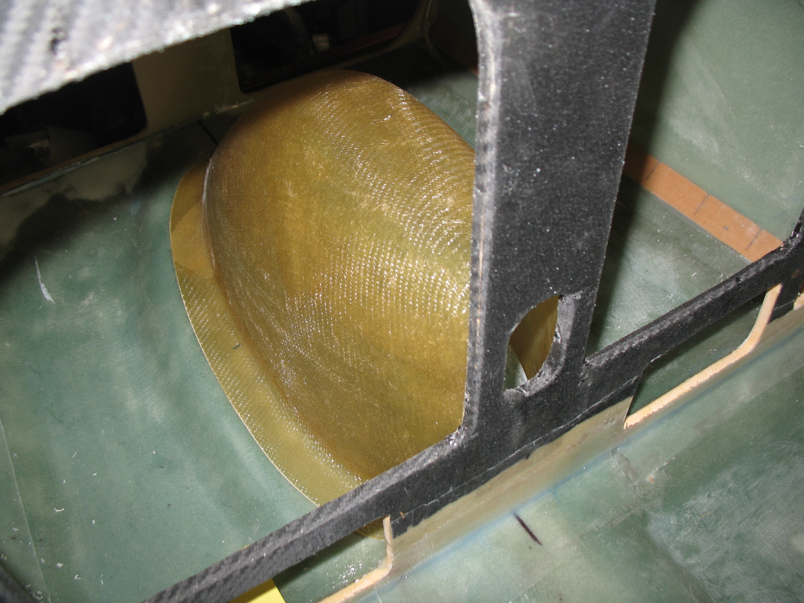
I measured out and designed the side fuselage openings that allow access into the strakes (wing root area). Specifically, access to the pilot & GIB’s baggage area. Guilty of some more slight modifications, I reshaped the oval front of the GIB’s opening to one that is slightly more ‘triangular’ (maybe a better description than C-5 nose-ish?!) and follows the curve of the embedded rudder cable conduit. I’ll also most likely extend the pilot’s strake opening to the instrument panel… somewhat of a Cozy Girrrl’s strakes mod for a Long-EZ.
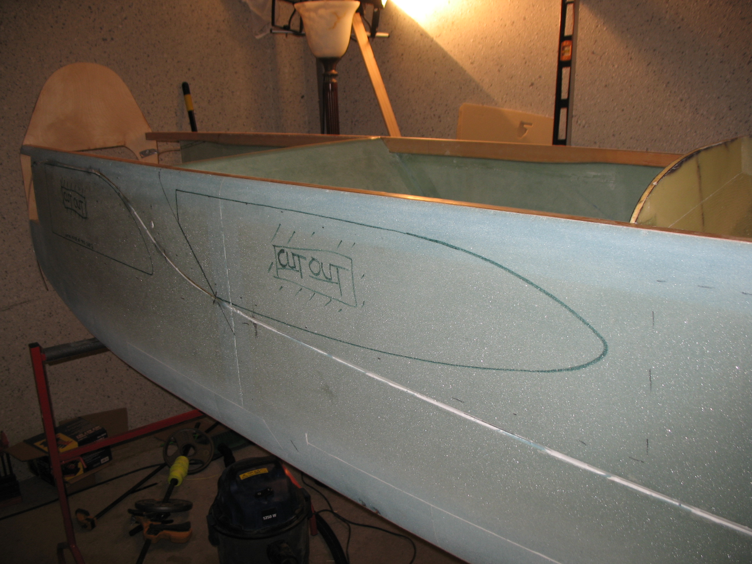
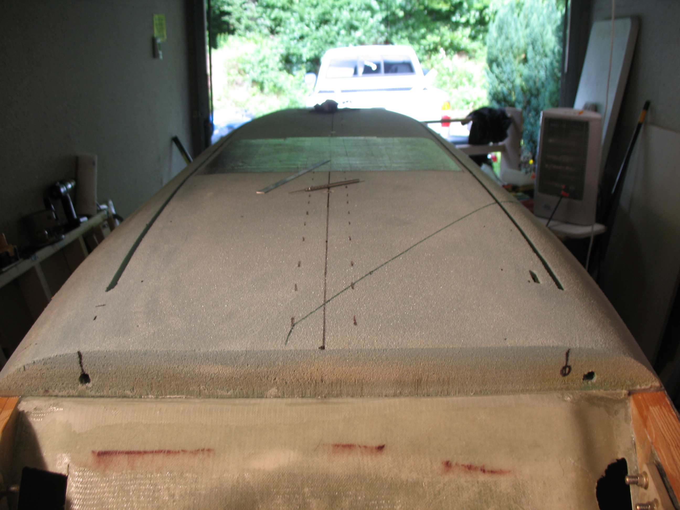
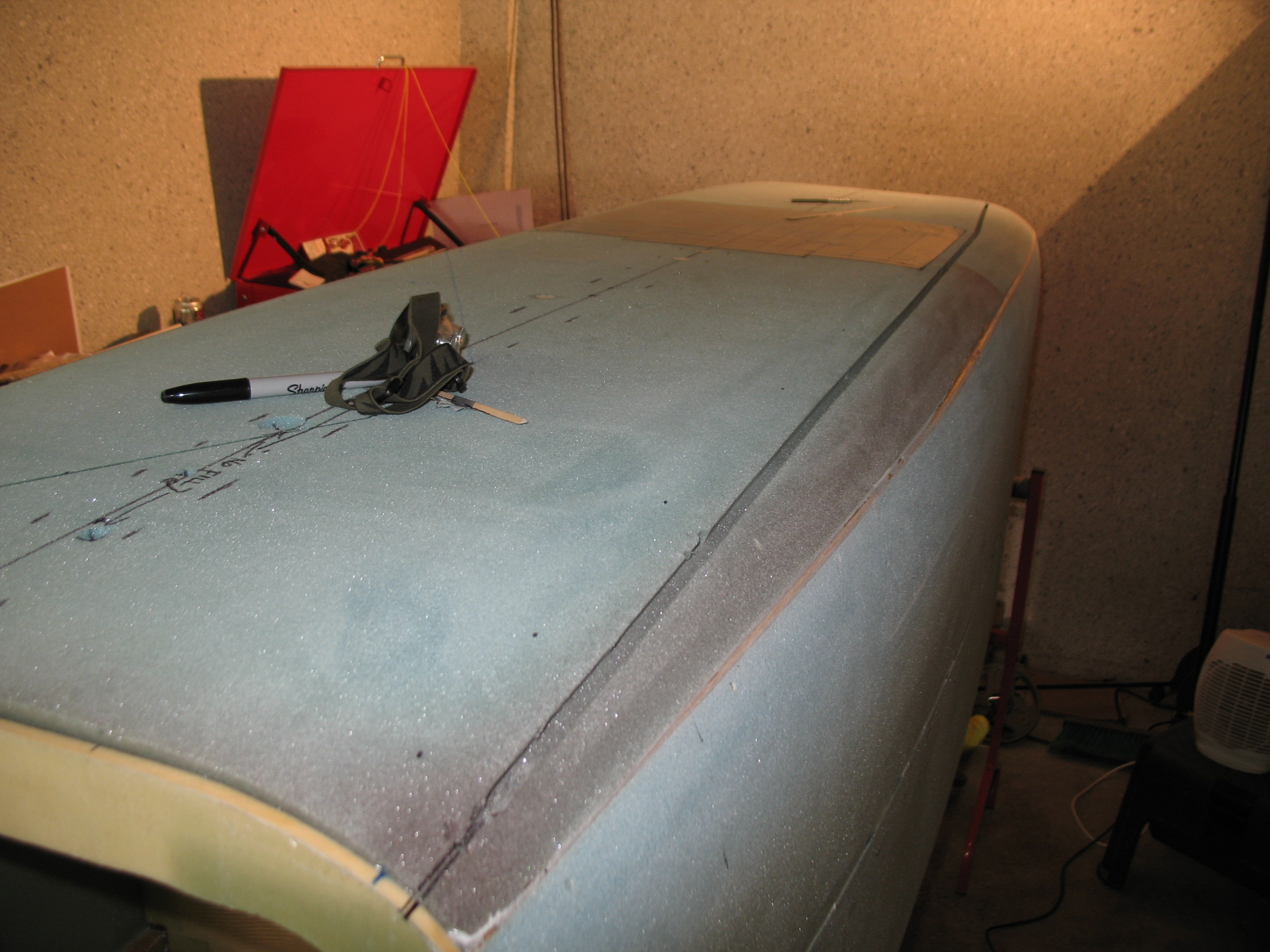
Next, I cut off the front top corners of the fuselage to create a “shelf” for the canard to sit in and be positioned correctly to mount to the F22 (front) bulkhead. The aft vertical line of this square area that gets cut out is drawn straight down from the front edge of the F28 bulkhead (the narrow one across the top of the fuselage). The plans call for a more invasive cut into the fuselage, but of course I’m deviating slightly by just making a simple square cutout without any of the jut-outs in the corner that the plans would have me make.
After the “lightening” of the fuselage above…ha! I did a little bit of housecleaning by sanding down a bunch of the heavier micro & flox rich areas on the fuselage. I also sanded down the longeron tops in prep for glassing (wood grain should be sanded so the epoxy grips it better).
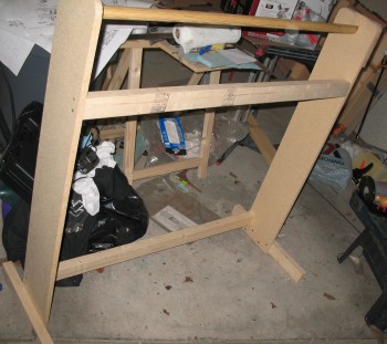
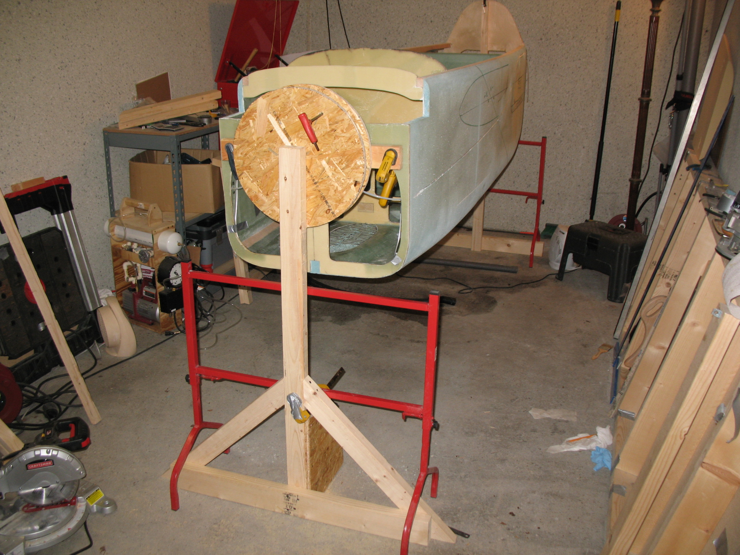
My last effort of the day was designing and constructing a fuselage “spit” so I can spin the fuselage in quick-fashion as I glass it. I got the front half of the spit completed with some good initial ops testing.
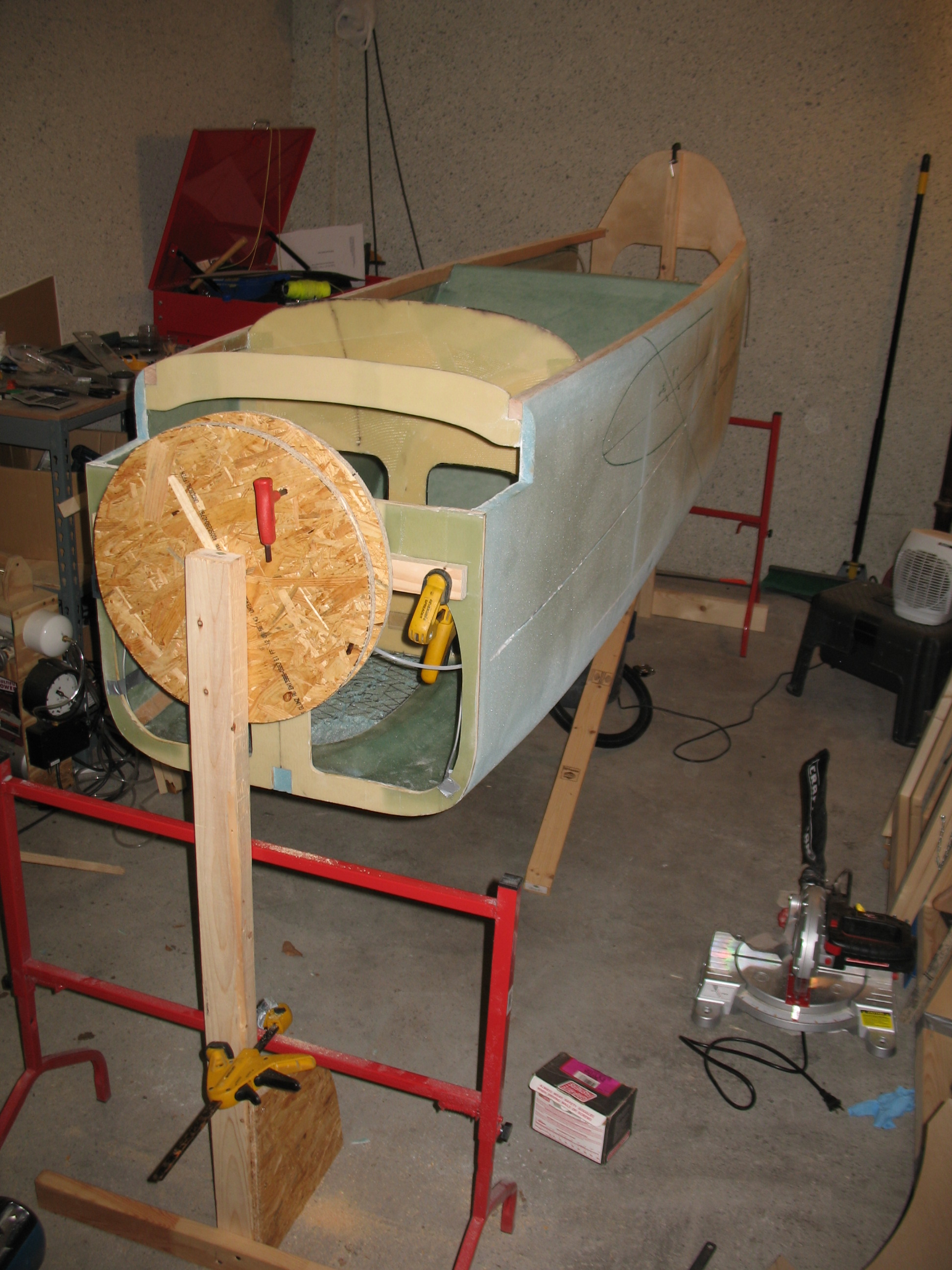
Lastly, with the fuselage upright I had the opportunity to take a good look (and some pics) at the seatbelt mounts on the inside of the fuselage. . . let me say: “those dogs will hunt!”
•••
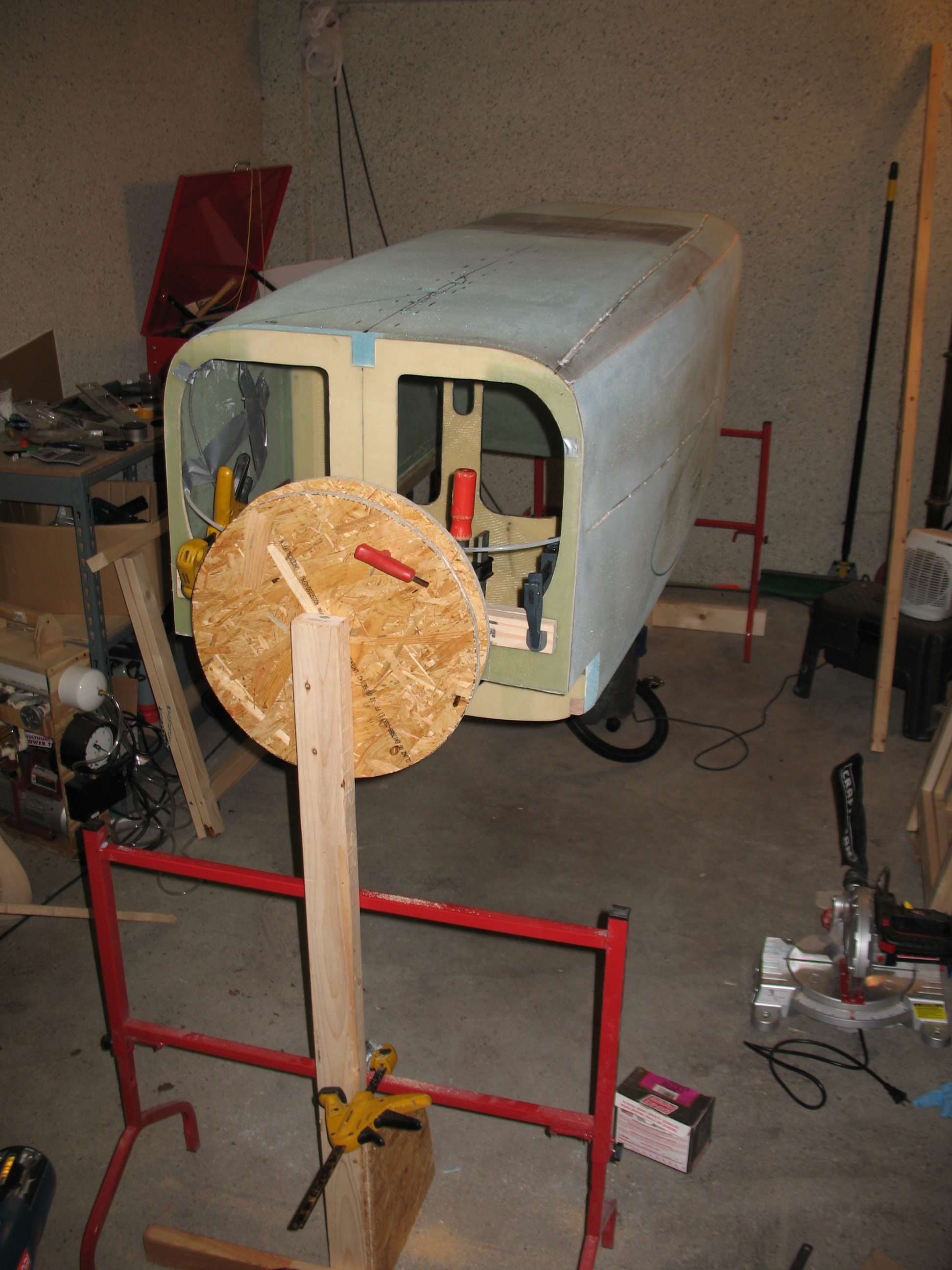
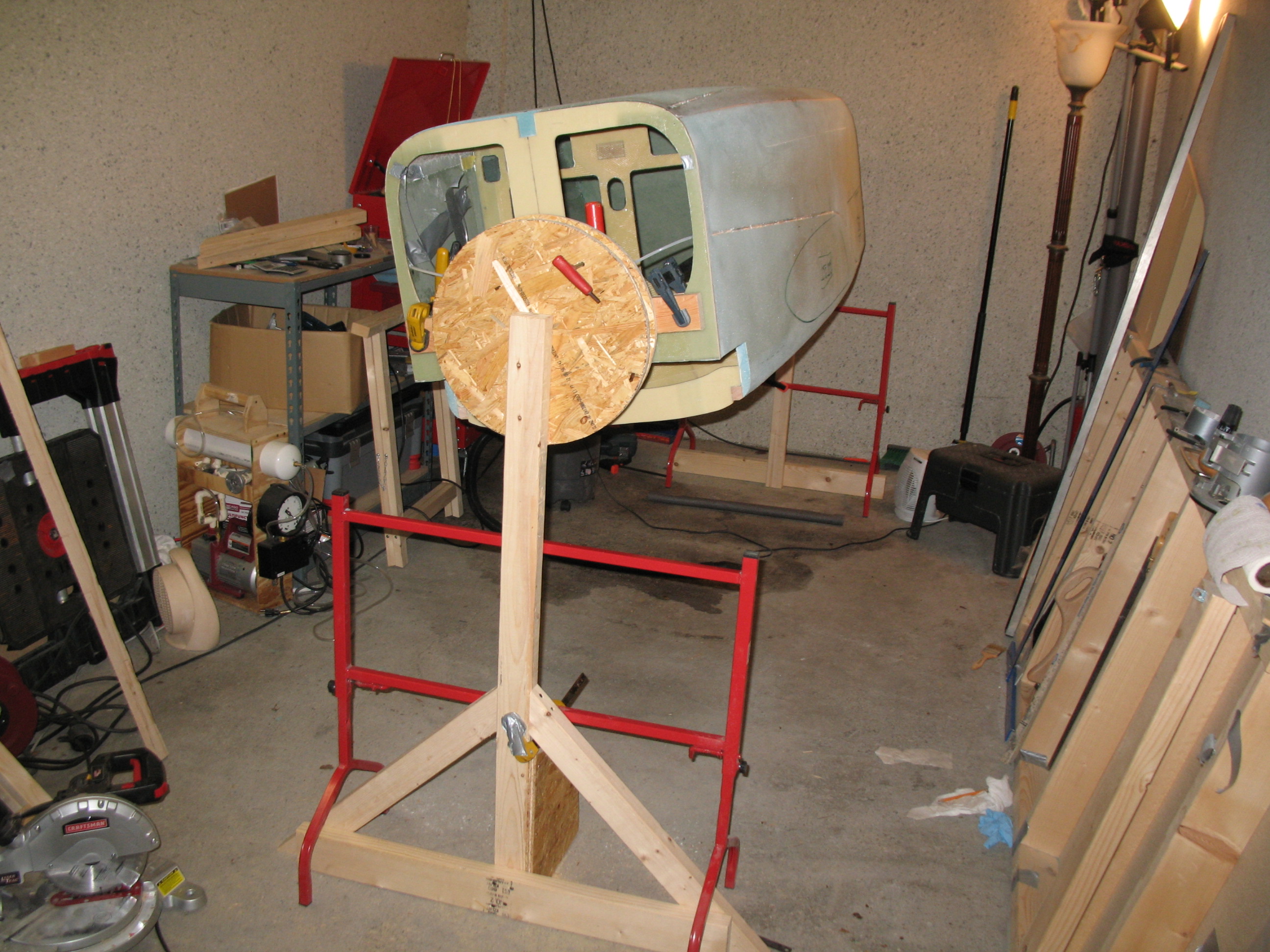
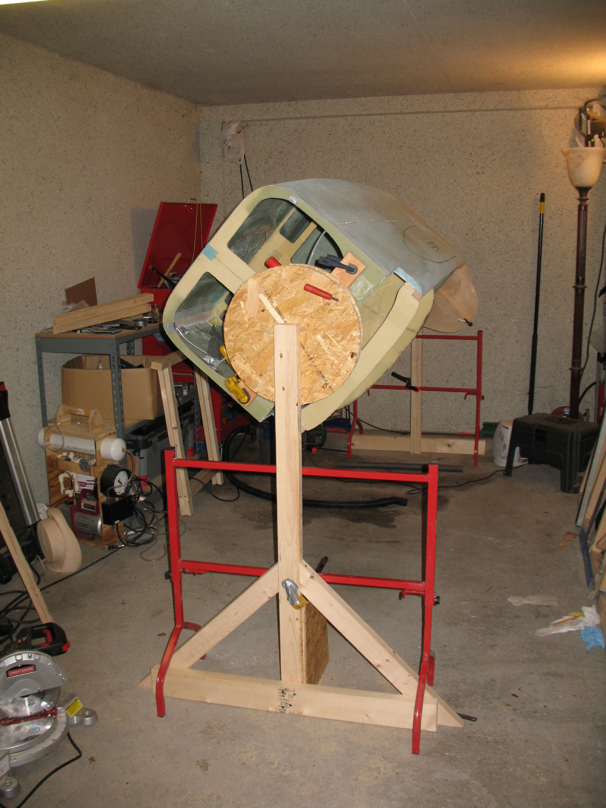
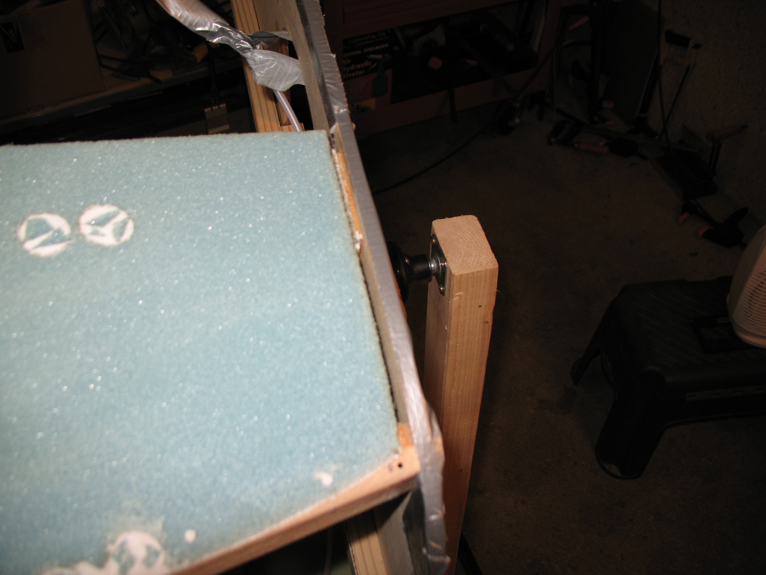
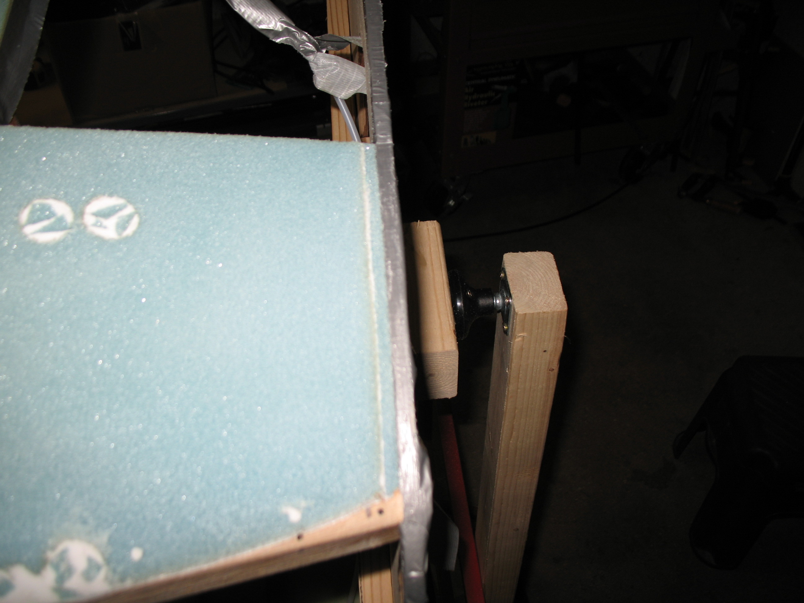
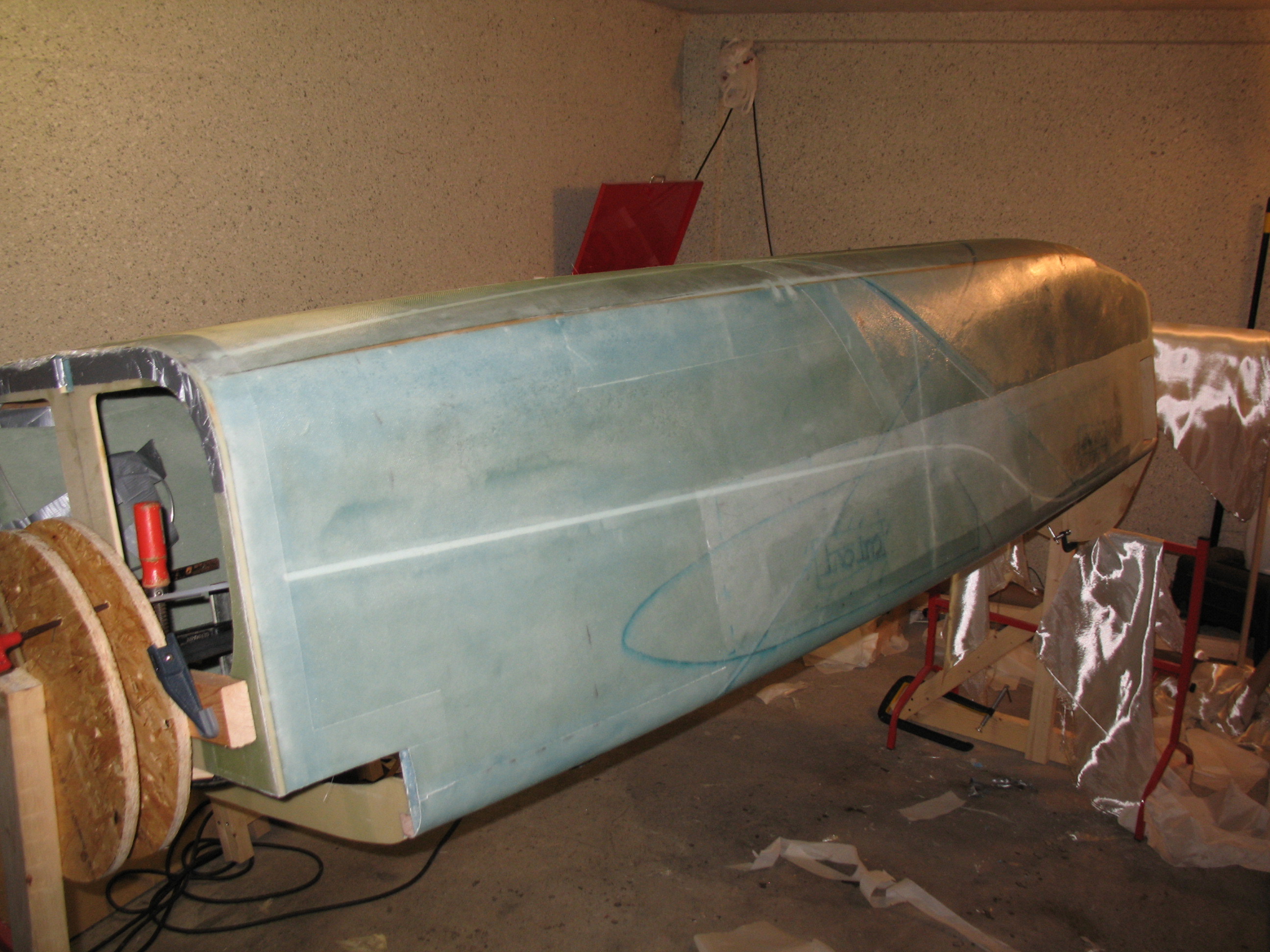
11 June 2012 — Tonight was all about finalizing the fuselage glassing spit design and getting it built.
I beefed up the spit with bigger pieces of wood and mounted the spinning part of the disc directly to the clamped mount in the front. I added more screws & longer screws to make it more stable. Finally, to really add some oomph to its lateral stability, I added some 45° angle braces.

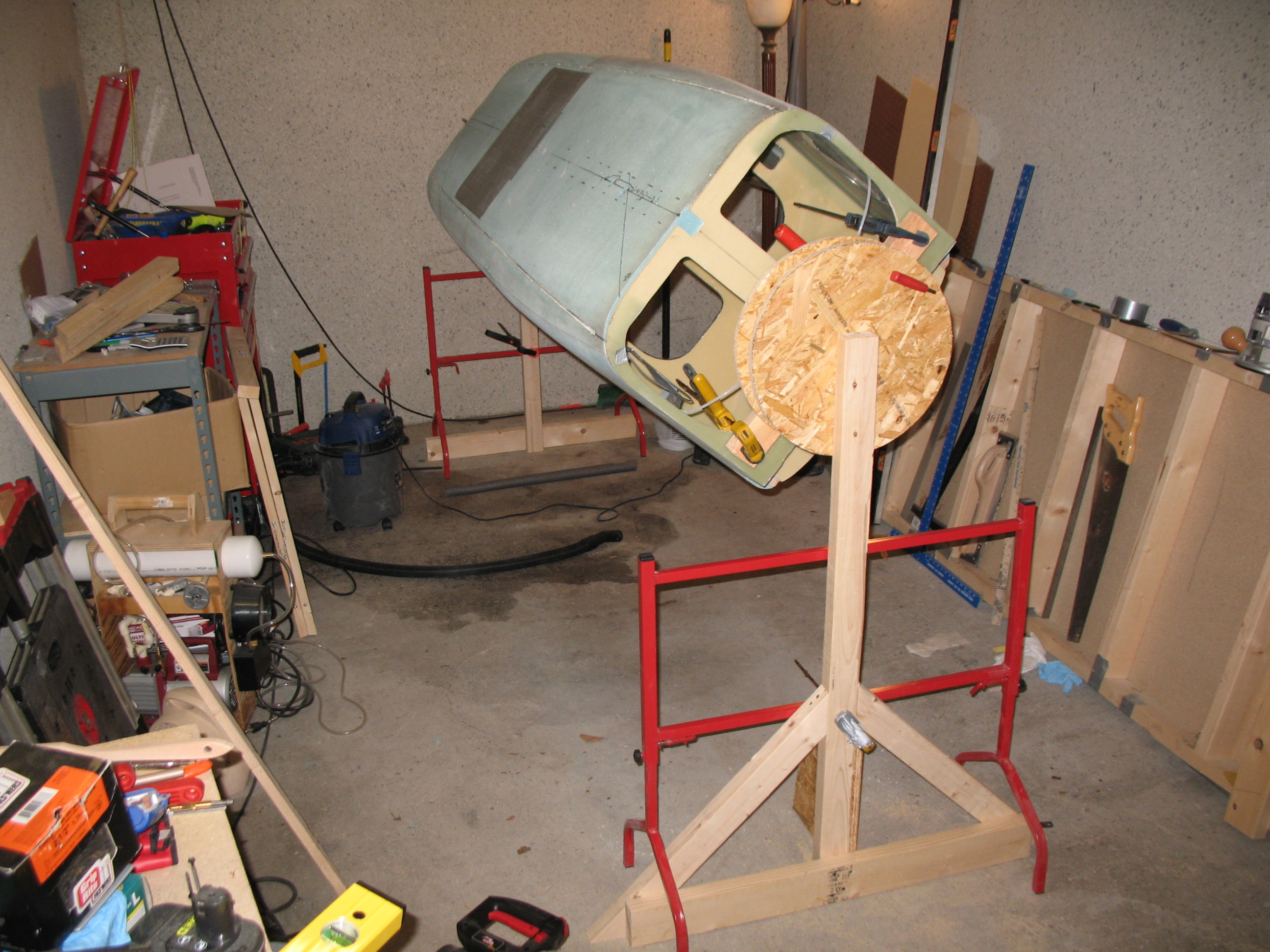
Side note: As you can see, underneath the rear of the fuselage there’s some water that I vacuumed up with the shop vac. I’ve been plagued by a leak in the corner downspout of the garage. The actual PVC pipe is too short, so I get to take my pick where I want the water to come in …. the top or the bottom. Luckily it hasn’t damage anything. It’s just an annoying time buster to deal with a work shop that has a large puddle of water in it. And yes, my landlord knows and is slow to do anything about it.
•••
12 June 2012 — Not much to report today.
I rechecked the spit structure and made a few slight modifications. I added another 45° brace to the rear spit upright. Then I taped up the firewall in preparation for glassing the fuselage.
•••
Greetings Dear Readers!
13 June 2012 — The good news is that I have much to report. The bad news is that I only have one pic to share . . .
Today I organized and cleaned the garage in preparation for skinning the fuselage exterior. I sanded down the lower stringers and then vacuumed the entire fuselage. I then finished taping the lower aft section of the fuselage and the main landing gear brackets in the “hell hole” area near the firewall.
I pre-deployed glassing supplies out to the garage. I also added another 45° brace on the fuselage glassing spit.
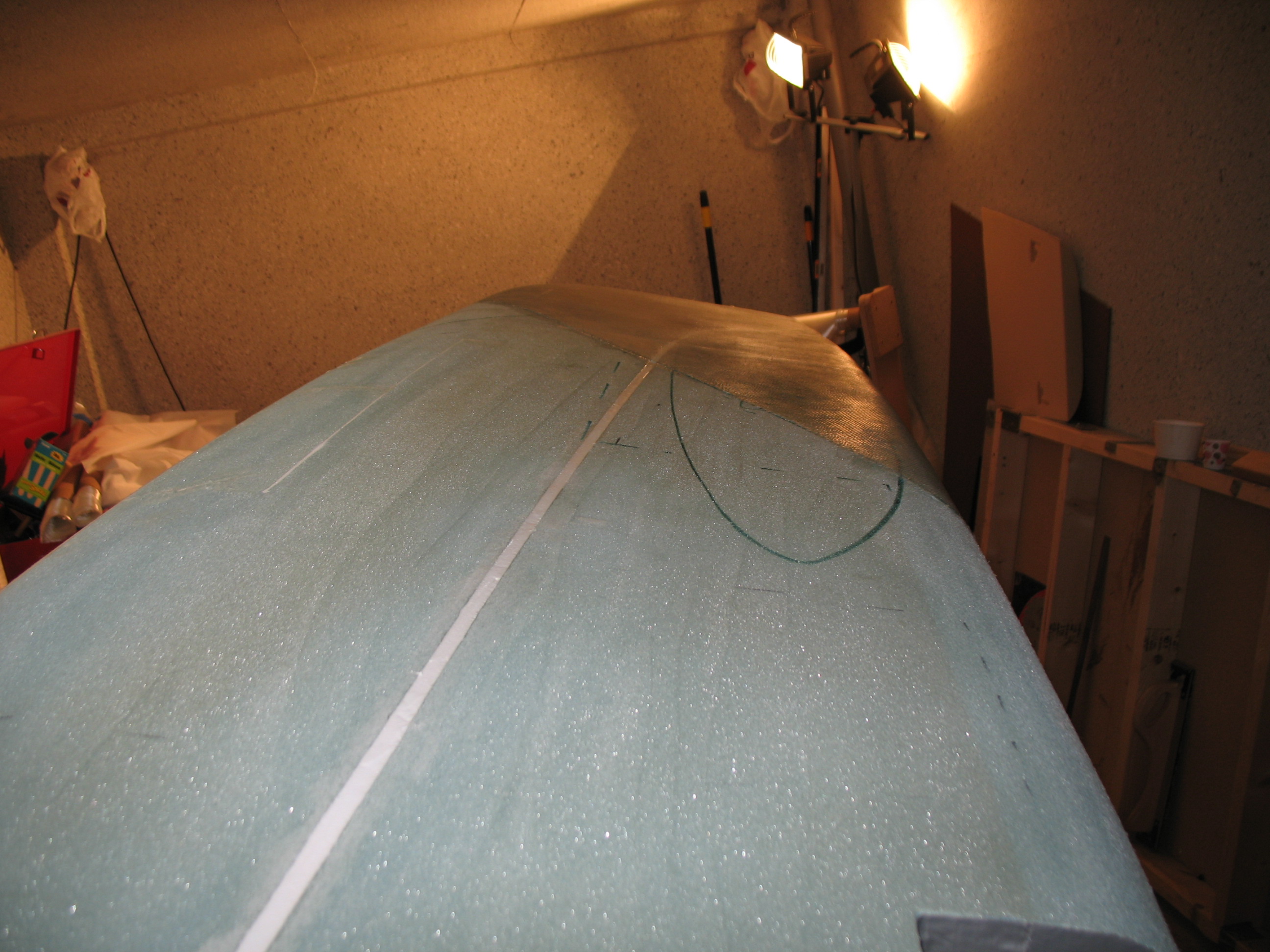
I marked the top longerons for the layout of the staggered 3-ply layup of 3″ UNI “tape” (NOT actual UNI tape, this is just plies of UNI cut into 3″ strips). Because I will be employing the Steve Volovsek/Ken Miller “Elbow Room Mod,” which enlarges the strake openings in the side of the fuselage further aft, I decided to add 4″ to each top tape so the resulting lengths are 56″, 54″, 52″ for each side (all obviously 4″ longer than plans).
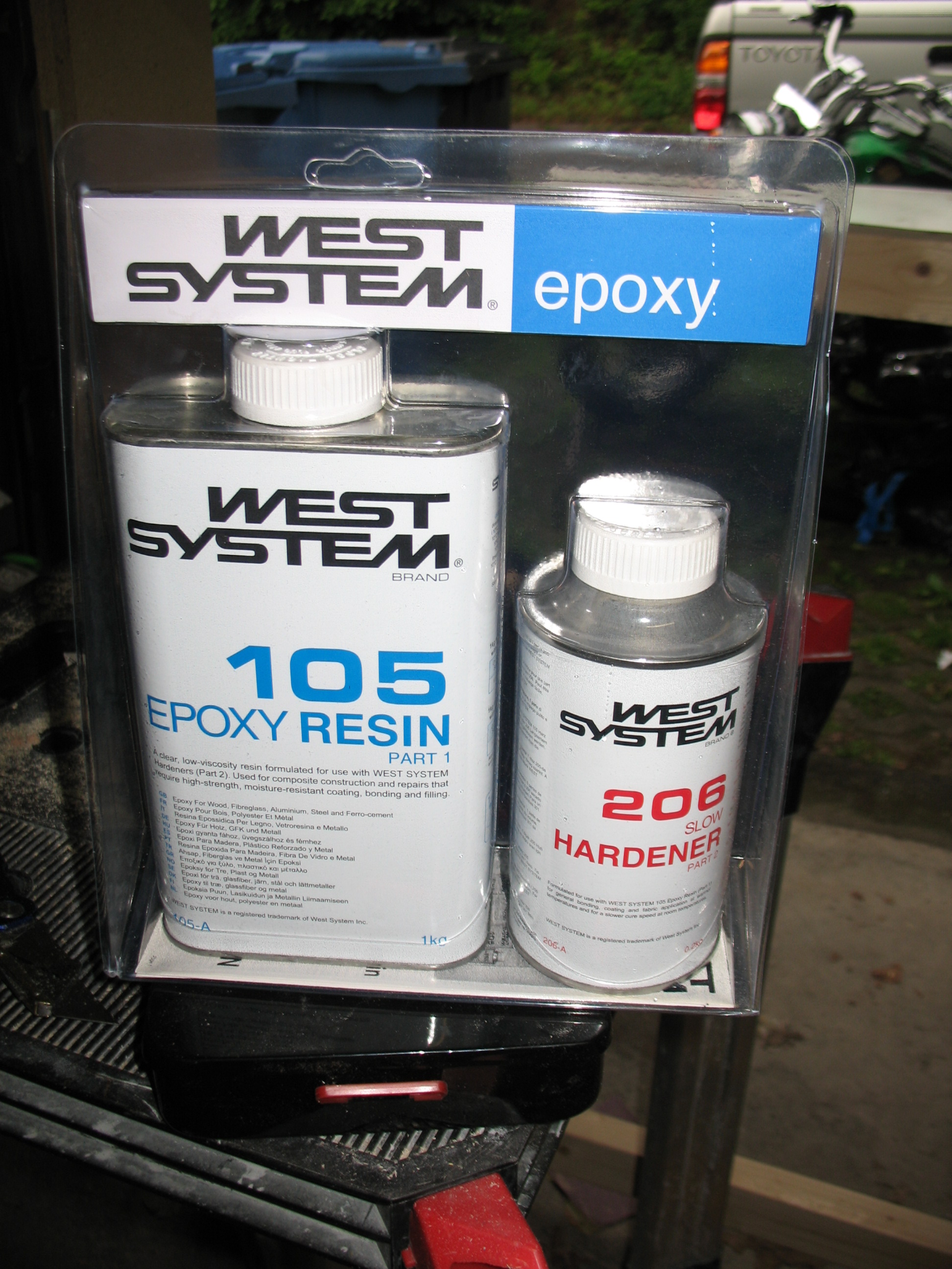
Finally, I’ve been researching the final fiberglass finishing techniques and systems for the last few weeks. I think I’ll go with West, but because of some reservations of a couple of actual builders that I’ve been discussing this with (who used other systems), I’m going to test it out first. I picked some up from a boating supply store here in Germany for my tests.
•••
14 June 2012 — Today I finalized the fuselage preparation for glassing the exterior skin of the fuselage.
While I was double-checking everything I realized that at some point I had been a little aggressive in my sanding & cutting of the foam at the back edge of the fuselage where it butts up to the firewall, on the Left side of fuselage. This past overzealousness created a small gap that needed to be filled, so I made up a foam wedge that was 0.2″ wide from front to aft, around 0.4″ deep (depth of foam in that location), and approximately 6.2″ in length from top to bottom. I then micro’d this foam wedge into place to cure.
I ops tested the fuselage glassing spit one more time and added some more screws to the front round disk to add strength and keep it from rotating where it wasn’t supposed to be.
I taped up the two threaded inserts along the fuselage bottom centerline to keep the epoxy out.
I used my Perma-grit tools to prep and clean up all the conduit channels so they would be clean for a fresh micro application.
I mixed up two more bottles of hardener and restocked the micro. I then repositioned the fuselage at an angle to make the sharp-angled 30° applications of UNI on the fuselage a little easier.
Finally, I played around with the pilot strake opening positions looking at the pros and cons of stock vs. extending the openings to the instrument panel (again, ala the Cozy Girrrls strake mod).
•••
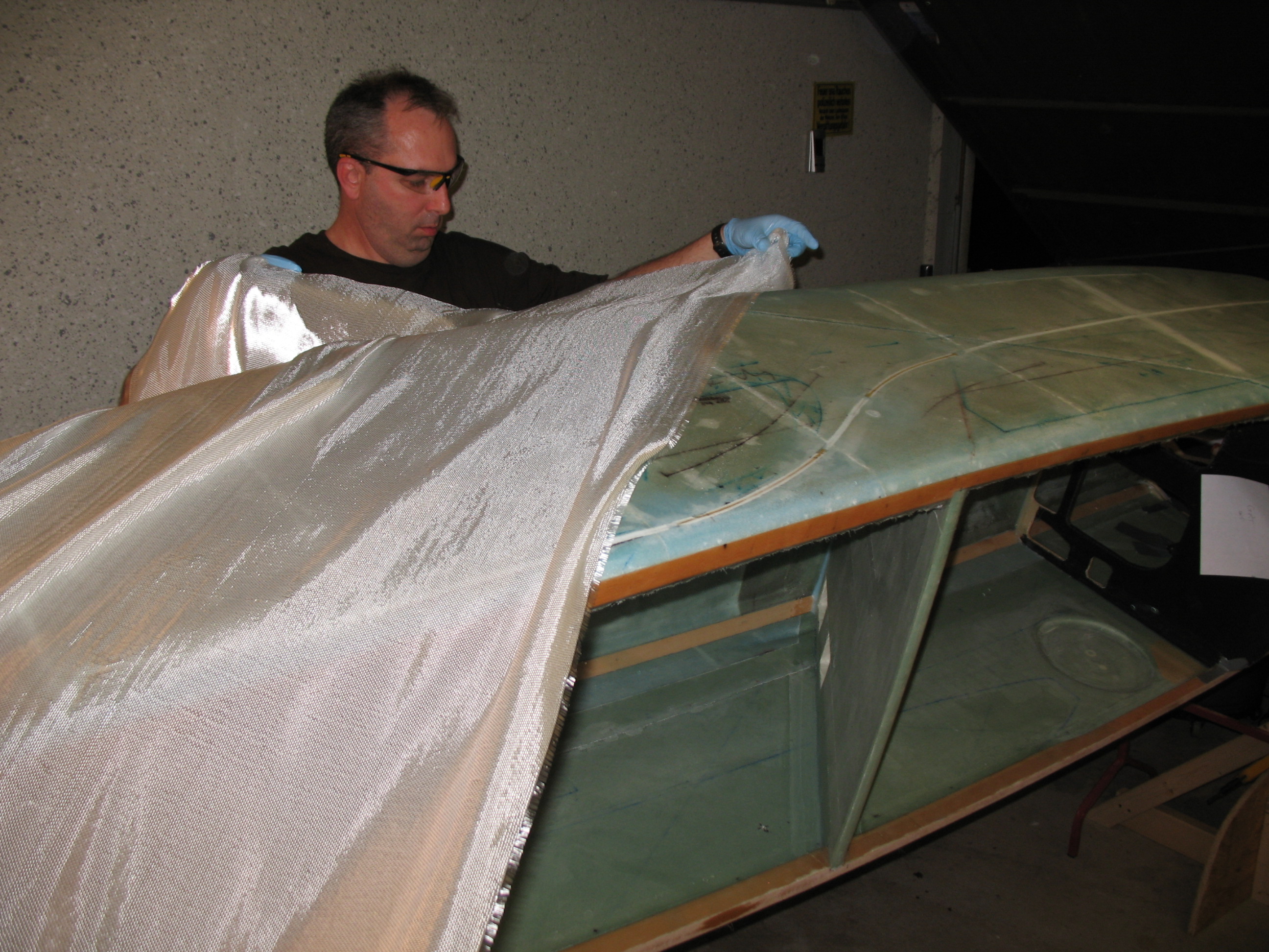
Chapter 7 Step 2 – Glassing the Fuselage Exterior
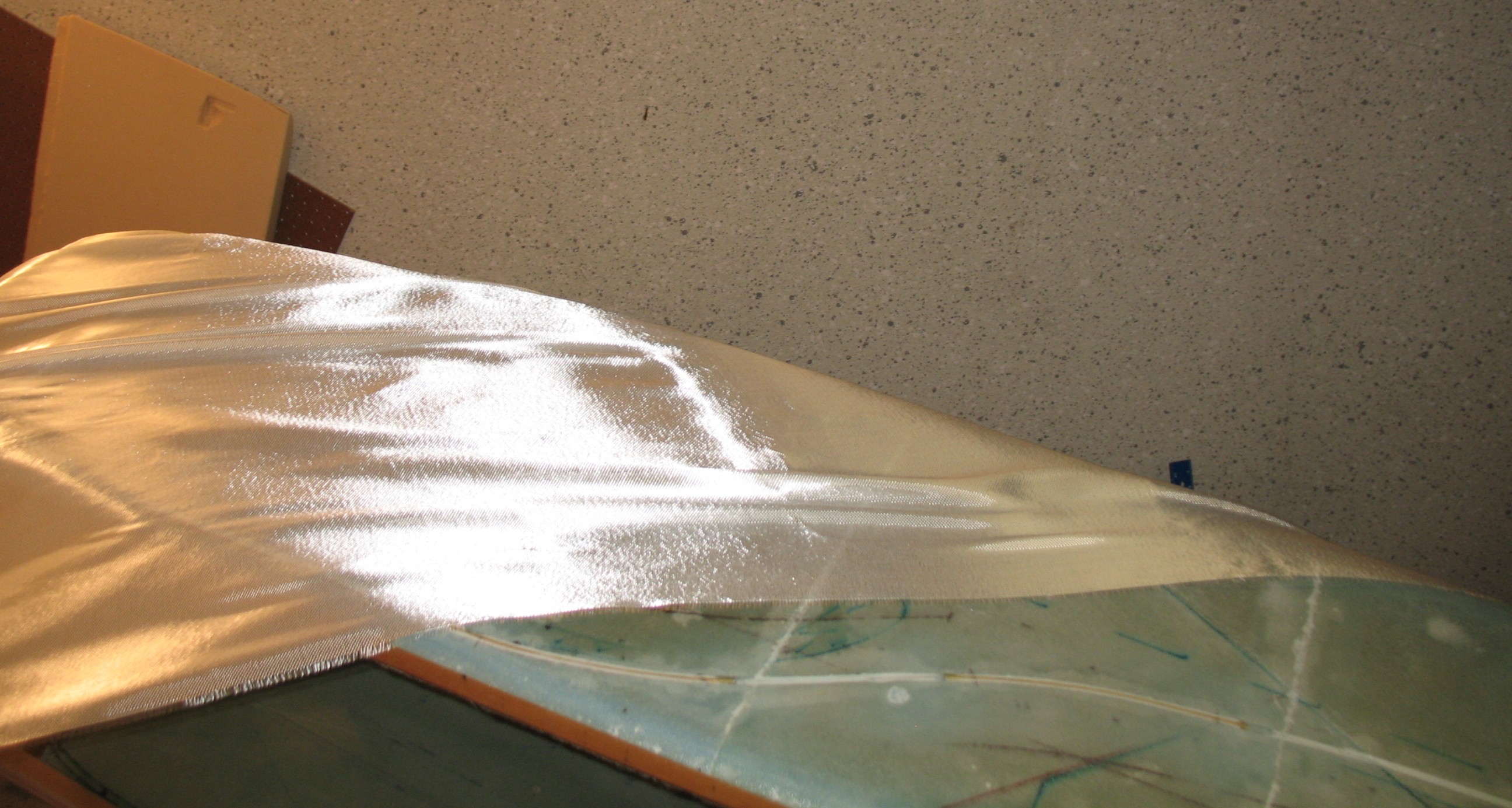
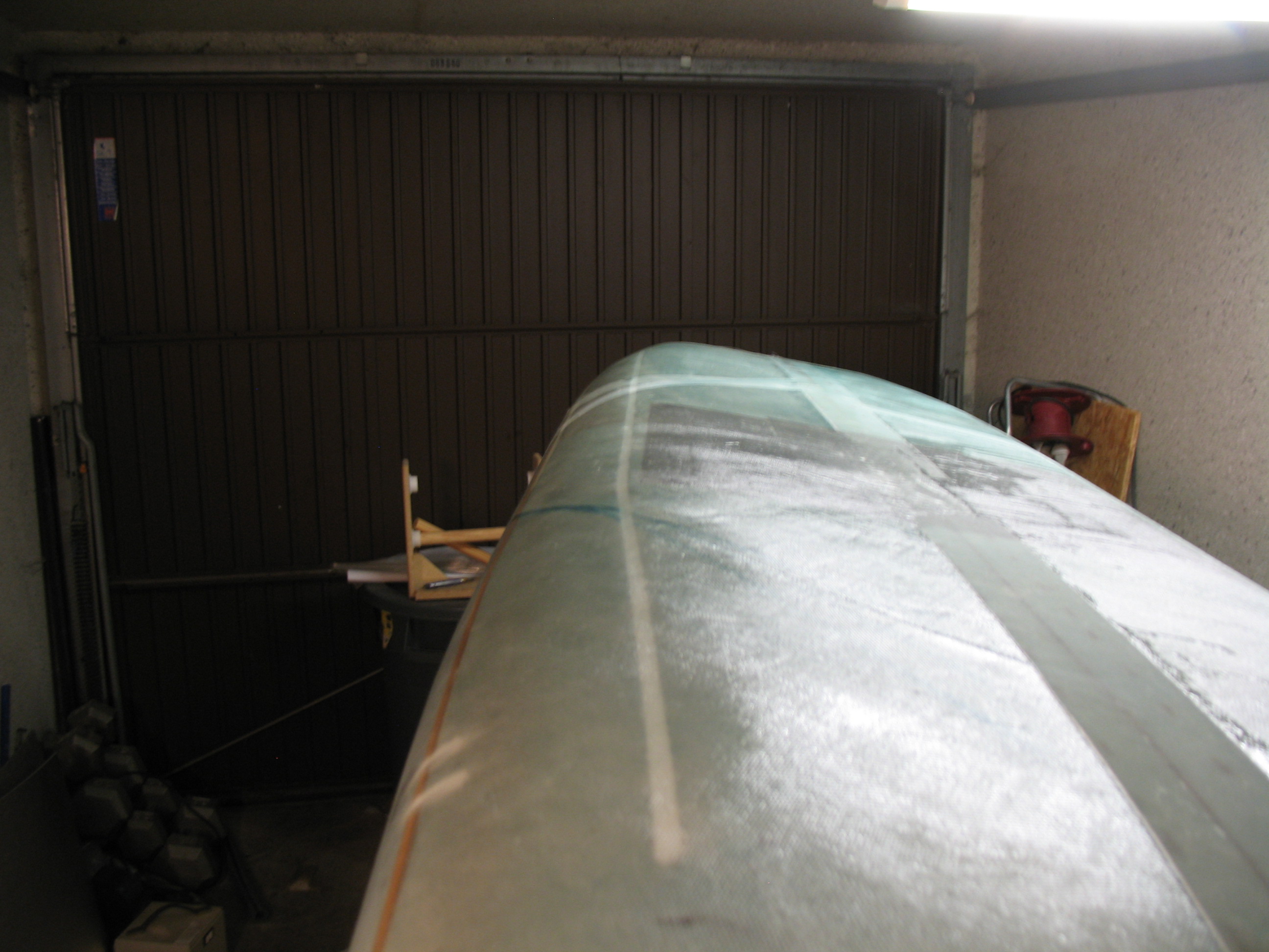
15 June 2012 – And so begins the final chapter in the saga of glassing the fuselage … or should I say the final step . . . of the chapter!
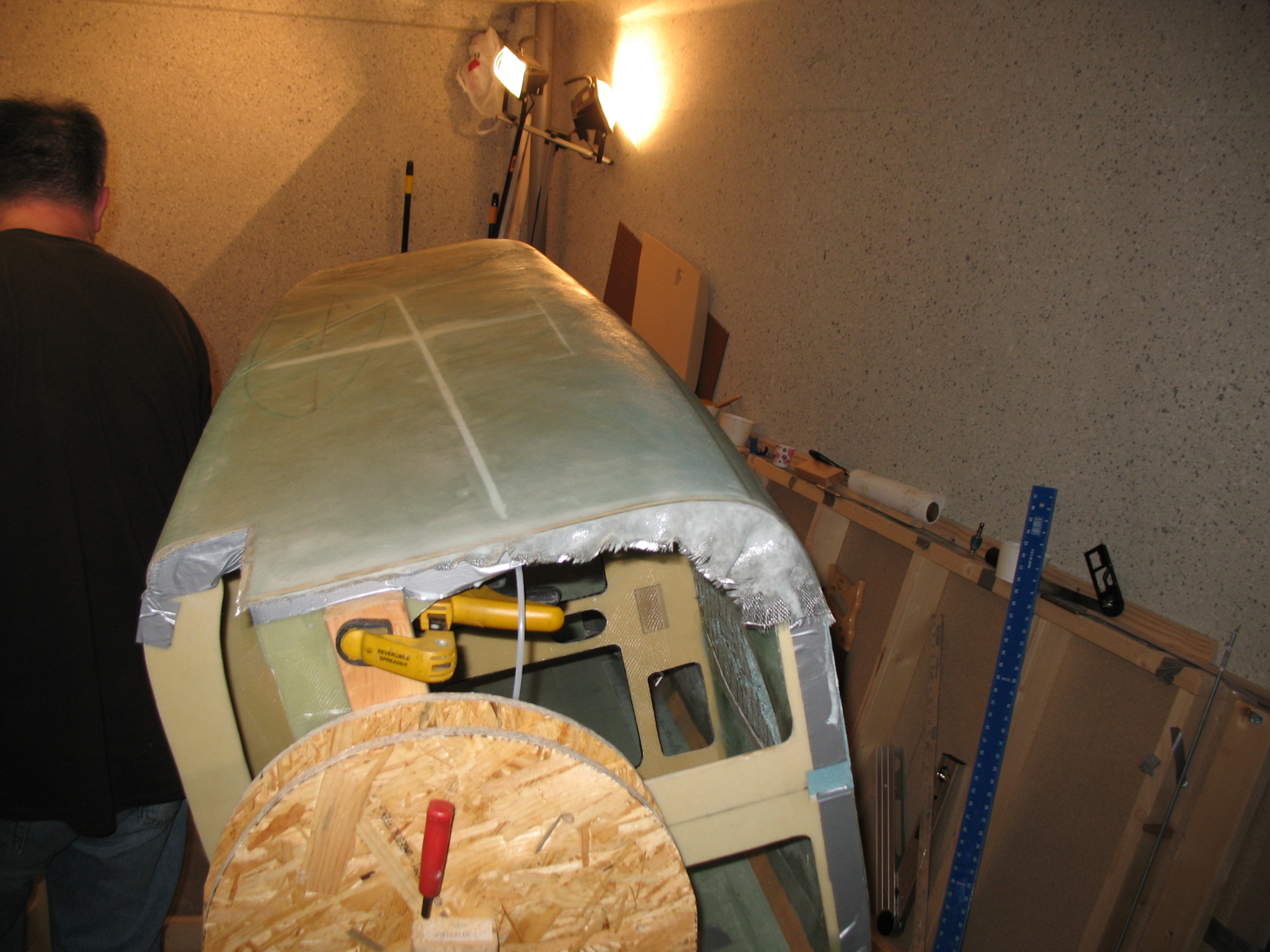
I pulled an all-nighter to glass the fuselage. The first the few hours were of course all about prepping EVERYTHING to get ready to actually start glassing. Below is a pic of the final filled-in foam strip at the rear of the fuselage.
I also reset the Left-side fuselage thread insert and filled the hole from the outside with a foam plug.
I cut two sets of 3″ UNI strips at 50″, 52″ & 50″ and set them up “pre-preg”.
I cut 2 pieces UNI for the third ply on fuselage & wrapped/rolled in brown paper.
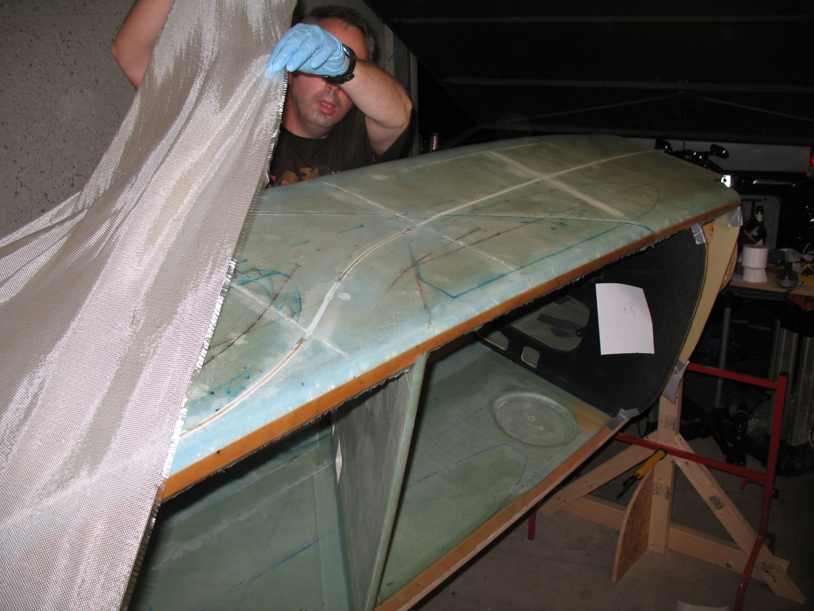
I cut a UNI roll at 30° on the end and took it out the garage.
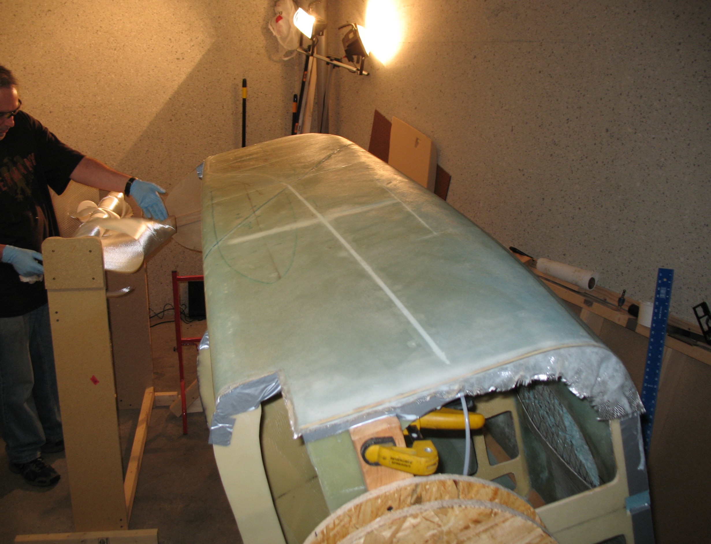
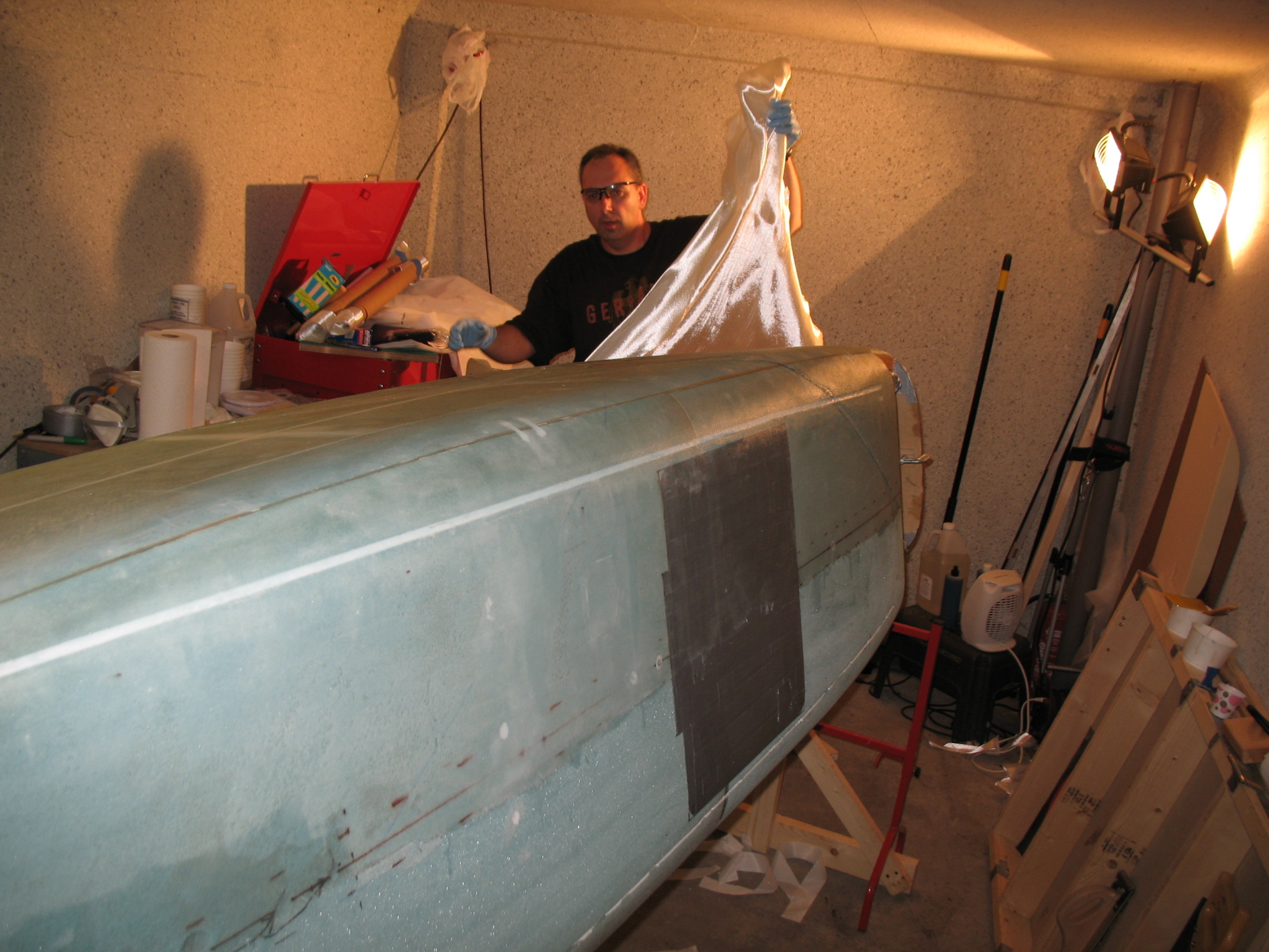
By the time I actually got started glassing, it was about 1930 in the evening. I glassed straight through until about 1430 the next day, after peel-plying critical areas and seams and trimming glass so it would cure nicely at the edges. In that whole time I may have take about four 5-7 min bathroom/snack/water breaks. Being by myself (minus the 10-minutes my buddy Kevin stopped by and took some pics with my camera), it was definitely a marathon glassing session. In retrospect, if I glass another fuselage by myself, I’ll most likely either stop half-way through, or pre-cut all my glass so it’s ready to go!!


•••
16 June 2012
The glassing continued on well into the evening . . .
The outside of the seatbelt brackets, under glass, came out very nicely. I’m very happy with my decision to install them first and glass afterwards, and keep from drilling holes through my freshly glassed fuselage skin!
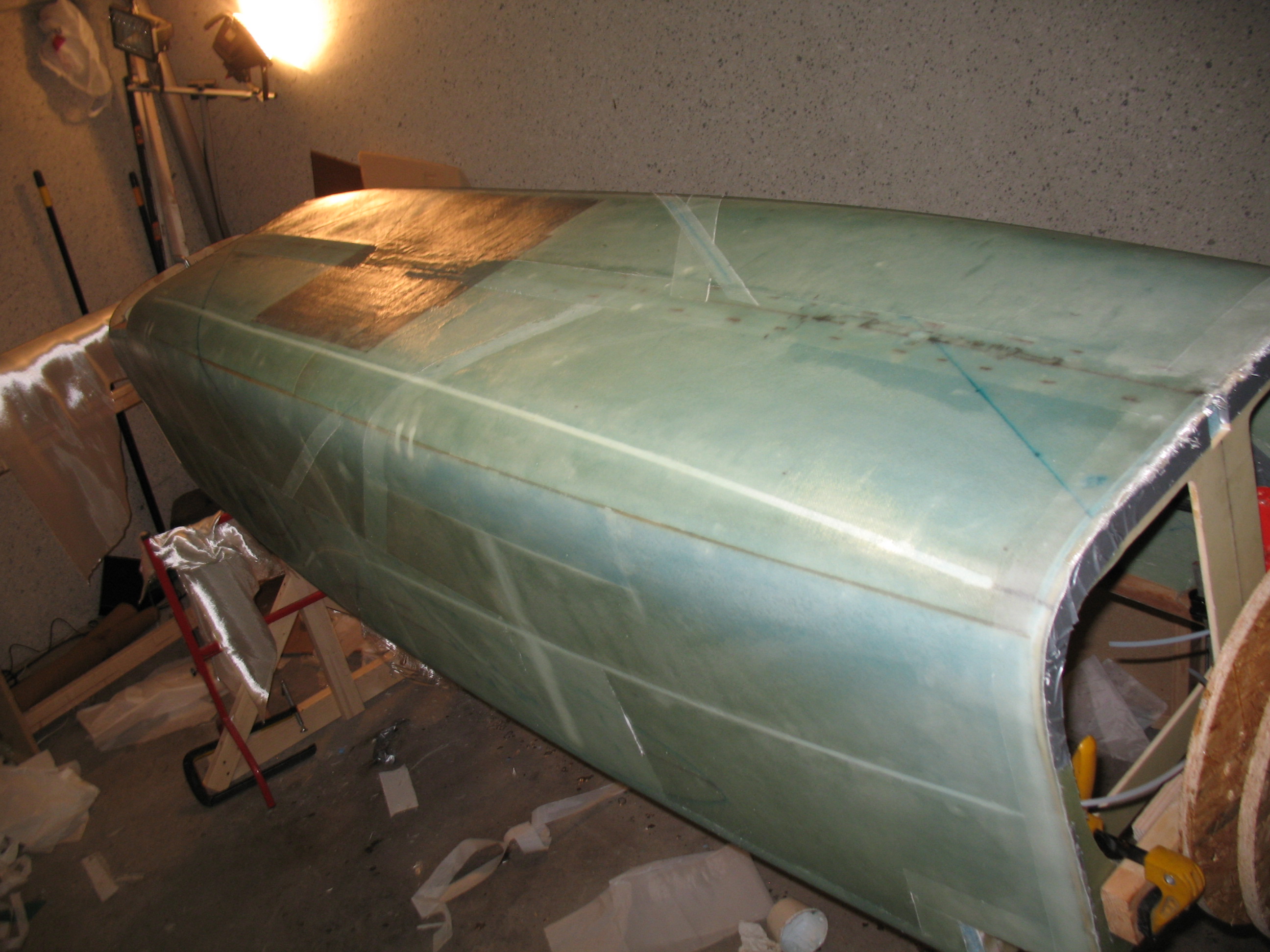
After I crashed for about 5 hours, I got up and checked the fuselage layup. Thank God I was using the ever-forgiving MGS 285 system! There were times where the bottom 30° UNI ply was getting fairly tacky by the time I laid up the opposite 30° UNI ply, but still took the next ply without balking. After a number of hours it all looked PDG! Definitely not perfect, and not an award-winning performance for certain, but the layups looked good, with enough epoxy that they don’t look starved at all, but not too much either… I think it’s a nice, strong fuselage!

Late Saturday evening I pulled the peel ply, cleaned up some of the threads, and knifed trimmed a few more areas I had missed.
I poured myself a Jack & diet, fired up a cigar . . . and then sat back and enjoyed the site of my freshly glassed fuselage!
•••
17 June 2012 – Today I started a massive multi-hour campaign to clean up “peel-ply snot” from the areas left from pulling up peel ply. Peel ply is great, but the raw carnage it leaves behind is something I think we plastic airplane builders forget over time. Anyway, with a fairly string-free fuselage I proceeded to prep for laying up the two sets of 3-ply 3″ UNI “tapes” (cut UNI cloth) along the top of each of the upper longerons.
Before I could layup the UNI tape sets, I had to take care of few air bubbles that insidiously crept into my fuselage glassing layup, mainly over the upper conduit areas. I used a hand drill to make a couple of holes in the glass and syringed in some epoxy. They weren’t that large, maybe .2″ to .4″ at the most (oblong, not round) here and there, but since they were right under my UNI reinforcement tapes, I wanted as much strength as possible.
 After removing the offending air pockets with injected epoxy, I started prepping for my 3″ UNI reinforcement tapes layup. I set-up my portable table and got a length of scrap particle board to use as a base for my squeegeeing activities. I then grabbed my 3″ UNI tape prep-preg set-ups and went to town.

Remember, since I’m removing a little bit more fuselage side material for a longer strake opening on each side, I added 2″ to each end (4″ total) of the 3 UNI tapes for final lengths of 54″, 52″ and 50″. I wet out one set of the UNI pre-preg and laid it up on the Right longeron. Once I had the Right-side longeron layup good & peel-plied, I moved on to the Left longeron.
And so ends a very long step in the completion of this airplane … and I’m just happy to be able to state:
Chapter 7 – Fuselage Exterior is complete!!!
•••
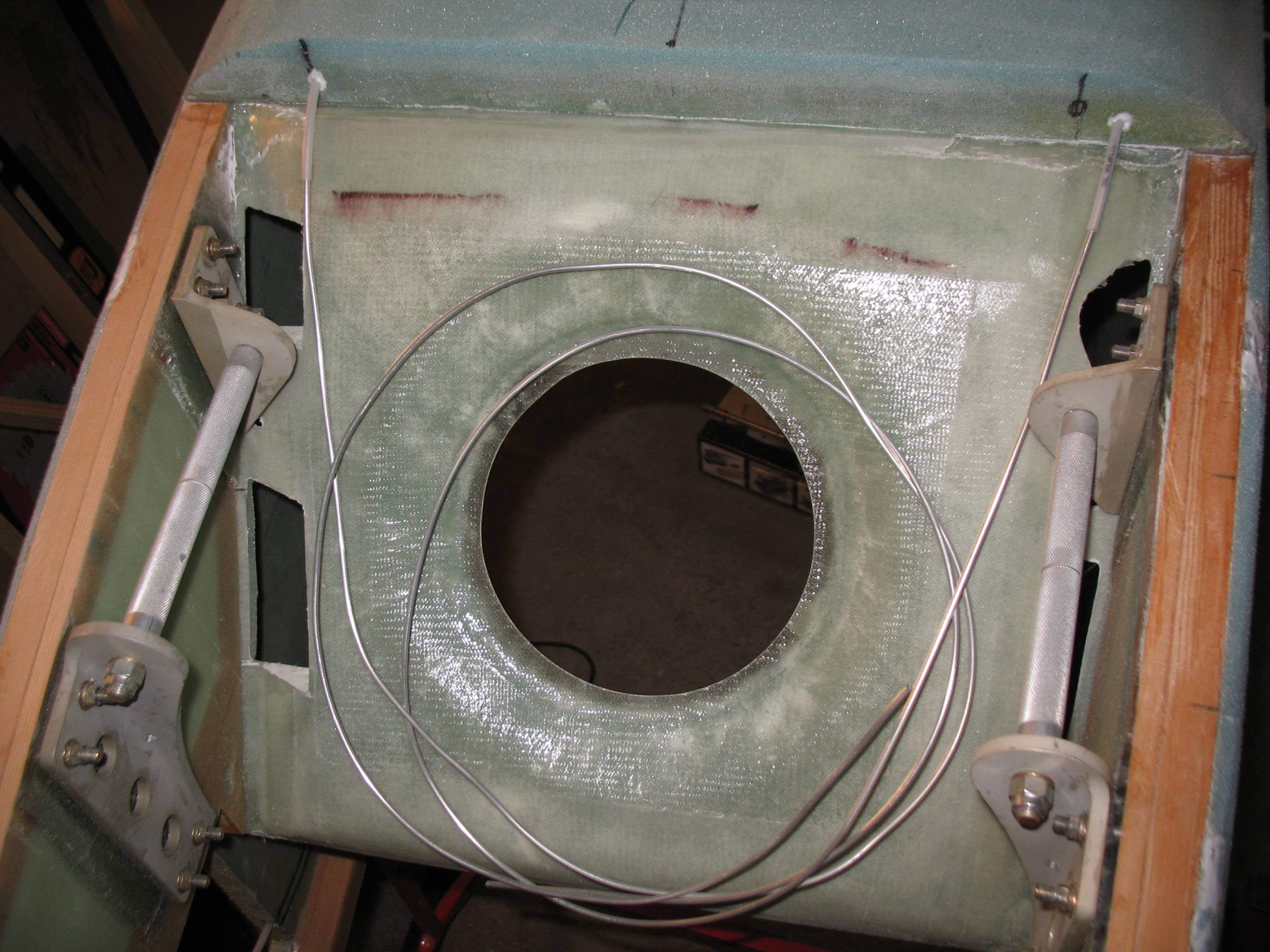
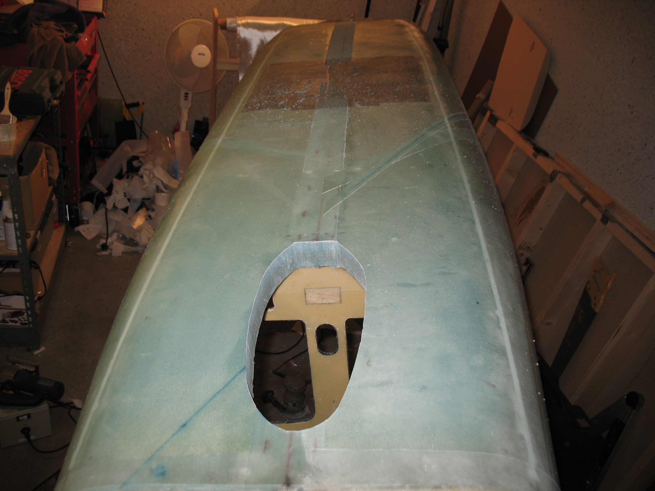
18 June 2012 – I finished up Chapter 7 (technically Chapter 6… but who’s counting??) by cutting out the nose gear well. I started by cutting a non-symmetrical shape from the inside, since I could see the actual shape outline and then grabbed the original fiberglass nose gear hole cutout from when I Dremelled it out earlier (that was after I mounted the fuselage bottom to the sides). After I cut the weird-shaped nose gear hole through the bottom of the fuselage, I set the cutout fiberglass piece back into place and taped it. Once it was securely in place and back in its original spot, I traced the shape of the newly cut hole.
 Once I had traced the outline of the hole, I removed the fiberglass cutout piece and moved it to the outside of fuselage to transfer the shape of the landing gear hole. Once I transferred the nose gear hole outline, I simply grabbed the jig saw and cut out the front nose gear hole.
If the nose gear hole looks a little non-symmetrical and uneven, it’s because it is. Since the plans have you cut it to shape based off the nose gear cover (NB), which is a purchased part, there’s not much you can do since it comes that way! However, once the nose gear cover was set into place the lopsidedness of the hole was fairly obscured. And once gear wheel doors are built and set in place, the irregular hole will be virtually invisible.
•••