
Chapter 7 – Fuselage Exterior
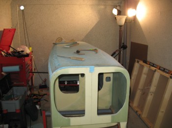
27 May 2012 — I pulled the peel ply from yesterday’s layups (corner 1-ply BID tapes discussed at the end of Chapter 6). Overall, everything looked great. I marked some punch list items and I’ll probably have to add another BID tape a place or two, but it all looks real solid.
I’ve had an observer while I’ve been working the past few hours:
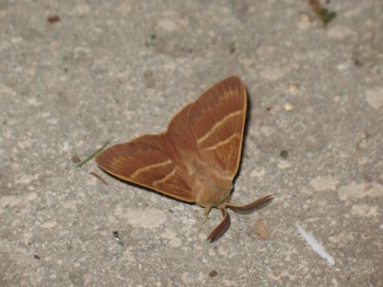
I think he’s been whispering, “Maybe you should have installed the wood block for the landing brake before you installed the fuselage bottom . . .” (shut up!) Oh, well.
I gathered and prepped all the tools I thought I would need for carving & shaping the fuselage bottom. This is big, and I don’t want to muck it up! So I’ve reread the plans about 5 times just to make sure I know EXACTLY what I’m doing . . . AND I’m 100% sure that I THINK I know what I’m doing!! So I dove in!
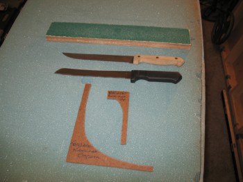
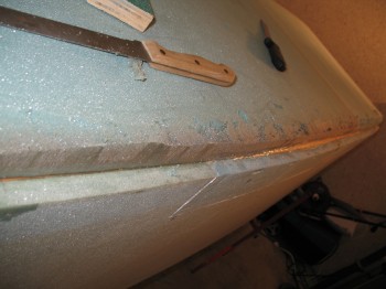
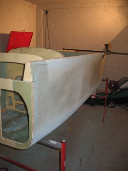
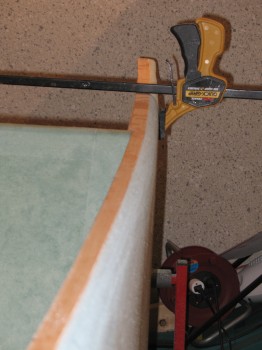
I started sanding and shaping the fuselage at the bottom corners to turn it from something that is basically square, and give it some curves. This took quite a while. I had to readjust the templates a number of times. Finally, to maintain a baseline on the templates I mounted a small level bubble on them so I could always start in the same plane at each point along the corner edge.
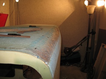
I got about 80% of the right-hand side and about 40% of the left-hand side (remember, it’s upside down) completed before I called it a night.
•••
28 May 2012 — I started off my Long-EZ build today by reviewing the early Canard Pusher Builder’s Hints and the Landing Brake plans for about 2 hours.
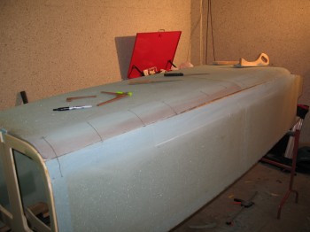
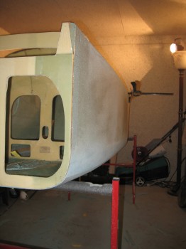
Then, because apparently it was Sanding Day (I hear Canardians are pushing for that to become a national holiday!), I sanded the bottom corners of the fuselage to shape. The final result may have just a little bit less foam taken off at the corners than the plans show, but the lower corners follow very closely to the template and have a good flow.
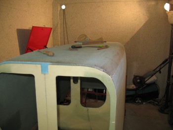
Shaping the top of the fuselage at the longerons, in time & effort, was comparatively EZ.
To be honest, I don’t really care for the shape of the top template… it seems a little too flat and could be just a bit more rounded. But maybe that’s what some folks say in general about the shape of the Long-EZ fuselage!
I also weighed the fuselage today. Mine weighs 46.6 lbs vs. Mike Melvill’s 41 lbs at this stage. Considering the extra glass, micro and flox I added both on the sides & bottom during the repairs, and the fact my rear longerons are a just a tad bit thicker, I’ll take the 5.6 lbs heavier fuselage and press on! Also, I haven’t given the fuselage tapes and repairs a thorough sanding yet, so that will take at least a little weight off.
And unrelated to the fuselage, once I finished shaping the fuselage I drug out all my raw 2024 aluminum pieces and marked up all the various pieces and parts that would come out of them. It was kind of like putting a puzzle together, but I had fun trying to plan the use the entire length of aluminum while minimizing any significant leftover pieces.
•••
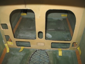
29 May 2012 — After a power nap I reviewed Chapter 7 of the plans on skinning the fuselage. I took a hard look at the strake cutouts as well (the holes on the insides of the fuselage that allow access into the “wings” to store baggage, etc.). I hauled the plans, A-pages and firewall out to my shop to mull over my next steps. I mounted the firewall and in doing so, noticed a few more hairline cracks developing in the foam fuselage at the aft end of each side. I need to get the fuselage glassed soon! I checked the firewall: it fits well and is square.
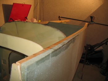
One thing that is not fully captured on this site is the planning steps that go into each build action. I have been talking to a number of highly experienced canard builders, and although they quite often don’t agree with each other on build methods or project mods, I take what they have to say with a lot of weight and consideration. I also understand that if I do anything outside of the guidelines of the plans, it will quite often be met with a fair amount of wailing and gnashing of teeth! In light of this, one modification that I looked at and assessed in-depth tonight was imbedding the rudder Nylaflow tubing into the fuselage sides. It looks quite doable.
What is the advantage of doing this? My rudder cables will be taking a more direct route out to the rudders from the rudder/brake pedals. They will travel in-line straight from the peddle down the side of the fuselage, make a shallow ‘S’ curve and run near the top longeron through the Center Section Spar (again, no fibers will be cut, just gently gapped about 3/16″ for Nylaflow clearance) and then turn out towards the rudders. Another plus is that it cleans up the interior of the fuselage and allows me to work on the rudder cable conduits on the outside of the fuselage vs. the inside, in pretty much the same manner as how the conduit is run through each wing.
I spent about an hour and a half mocking up the tubing path and how it corresponded with the strake cutouts, using as gentle of curves as possible.
•••
30 May 2012 — I finished sanding the fuselage near the Main Gear extrusion bolts, and the Firewall junction with the CS (Center Section) Spar both top & bottom. I then sanded the top & bottom longerons to match the Firewall outline.
I checked that the fuselage was level and straight. I also double-checked the firewall positioning and confirmed that it was level, straight and square.
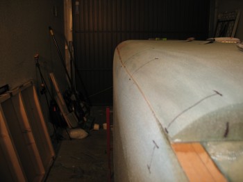
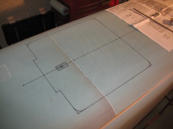
My last action of the evening was finding and marking the fuselage centerline.
•••
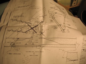
31 May 2012 — You might be asking yourself, what the heck is “Section VI?” when the only references so far have been to the chapters within the build plans. Yeah, well, I think a lot of us builders asked that same question at one point as well. And, yes, the Section VI plans are a bit of an anomaly. These plans cover the construction of the Landing Brake and actually have their origins from the Vari-Eze plans (it even states Vari-Eze Section VI Plans on the front page). They are referred to in Chapter 9, the Main Gear plans. Thus… mystery solved!
I spent over an hour studying the Section VI plans to determine what applied and what is different since I’m using Jack Wilhelmson’s Electric Landing Brake Actuator. By using this actuator it wiped out a considerable amount of the Section VI plans.
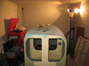
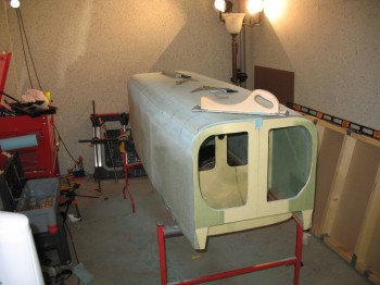
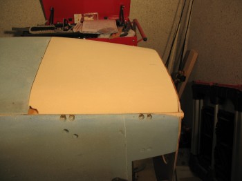
The reason why the Landing Brake comes into play at this point is because a layer of tape—which a glass layup can’t bond to—must be laid out onto the surface of the fuselage foam in the shape of the landing brake BEFORE the fuselage is glassed. Since I marked out the fuselage CenterLine last night, it was simply a matter of finding the fore & aft measurement as to where to locate the Landing Brake. After I found the forward location of the fuselage I marked up the outline of the Landing Brake. FYI – my Landing Brake is 0.94″ forward from stock plans due to my moving my front seat that much forward to assist the shift in CG since I plan on using a heavier IO-320 engine.
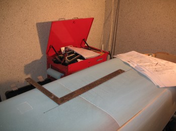
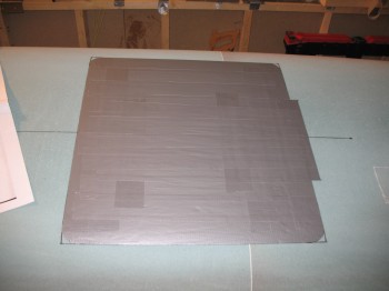
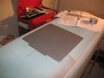 After drawing out and covering the Landing Brake area with tape, I finished the final sanding & shaping of the foam and wood longerons at the aft end of fuselage.
I then cut out and shaped the rear cover for the Main Gear cover (its moniker is the “Hell Hole” cover). This is just the initial shaping of this cover for this space. I’ll refine it later after the Main Gear is mounted.
•••