Chapter 5 — Step 1 of 4: Shaping the Foam Sides
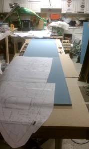
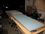
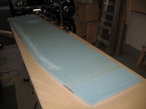
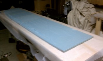
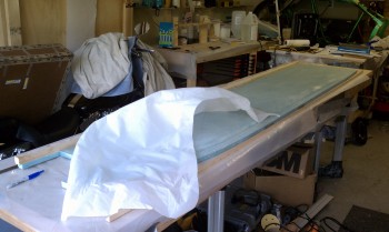
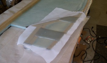
5 May 2011 – Table prep and 3/4″ foam for the fuselage sides being measured marked and prepped to cut the side outline. The two pieces of large foam have already been joined at the seem with an epoxy microslurry, or again what we call “micro” for short. Micro then also becomes a verb as in, “I micro’d this foam so it’s ready to go.” Micro is a mixture of epoxy with tiny (~70 microns) hollow glass microspheres (bubbles) that act to fill in the porous surface of the foam and thus induce lightweight air (inside the bubbles) to the seam between the foam and surface layer of epoxy, rather than have the whole entire foam surface saturated with pure epoxy. Pure epoxy sitting in the irregular foam surface aggregated over the entire construction of the airplane would and a lot of weight in pure epoxy vs the much-reduced weight gained by prepping the foam with an epoxy slurry. Micro can be mixed in 3 forms: micro slurry 50/50 epoxy-to-bubbles, micro paste is about the texture of peanut butter, and dry micro is almost, but not quite, crumbly.
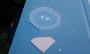
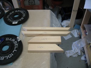
Above, what will be the aft end of the fuselage marked for cutting for what will eventually make up the bottom aft contour of the fuselage, and the entire fuselage side wall looking forward.
•••
Chapter 5 — Step 1 of 4
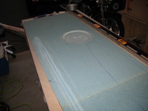
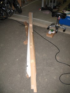
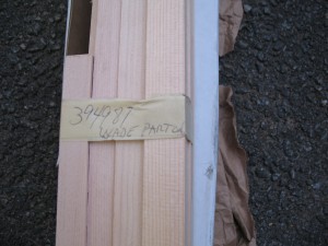
7 May 2011 – Today I finalized the cutting, trimming, and shaping of the right-side fuselage foam. Below you can see the round control stick depression in the fuselage sidewall. This will provide a little but more space for my right hand when I use the control stick to bank to the right. I also mocked up the front and rear seat bulkheads… so far so good! Also, the Spruce shipment I received from Aircraft Spruce in prep of building the fuselage longerons, stringers and main landing gear hard points.
Above, the interior of the right fuselage sidewall with markings. You can see the round control stick depression, the non-plans routed wiring channel near the bottom of the fuselage (credit to BizMan for the idea) and the markings from top to bottom for the instrument panel bulkhead (just forward of the sidewall stick depression) and the armrest positions for both the forward and aft seats (just below the sidewall stick depression).
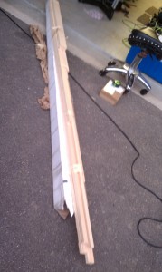
Also, also the Spruce required for just the fuselage build.
•••
Chapter 5 — Step 1 of 4
8 May 2011 – In this post you’ll see the Right Fuselage Side finished and ready to go, as shown below. I added a non-plans hard point just forward and about even with the top of the fuselage side control stick depression. The hard point is made of 1/4″ Finnish Birch and will be used as a foundation for a RAM accessory mount, maybe anything else that crops up in the future as well. With the instrument panel it place, it will sit just in front of the panel and tucked away under the top longeron. I micro’d it in and weighed it down while it cured.
Next, the Left Side Fuselage is made out of a much larger number of pieces of small foam as compared to the three (3) pieces that make up the right side. This is per plans and it allows the builder to save costs on foam. Once under fiberglass, the left side fuselage will be just as strong as the right side fuselage, even though it’s made up of a lot more pieces micro’d together.
The left side and right side sets of LWX and LWY spruce hard points literally tie the entire major components of the Long-EZ together. LWX serves as the rear seat mounting brackets on each side (only mounted with FLOX and fiberglass) and also as the main gear’s front bracket hard point. LWY serves as the main gear’s rear bracket hard point for the top side of the bracket, and each side acts as a shelf to hold up the CenterSection (CS) Spar where it crosses through the fuselage in the back. Moreover, LWY gets bolted to the CS Spar on each side to a piece of angled metal that also juts rearward through the firewall and makes up the two lower engine mounts.
Chapter 5 — Step 2 of 4: Fitting the Longerons and Laying Up the Inside Glass
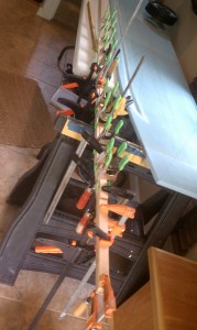
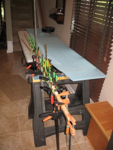
I carted the right fuselage side inside to the foyer of my house, shown with the RAM mount hard point curing (top of pic). I had to get it out of the way and off the main work bench so I could micro all the pieces of foam together that make up the left fuselage side. The clamped monstrosity in the foreground is the top longeron, which is constructed of two pieces of Spruce floxed together. Since I already cut out the firewall about 1.2″ wider than stock (I made every bulkhead wider), I had to then make the longerons and lower stringers (longerons) wider as well since the engine mounts sit on the inside of the longerons. Thus, to make a stock engine mount work I had to bring the mounts back inboard (thicker longerons) to get the mounts back into what would be their original plans-sized position.
Below, the Spruce used for the entire aircraft build. Since it was my first time building with Spruce, especially on a real aircraft, I commemorated the moment with a pic of the label.
•••
Chapter 5 — Step 2 of 4
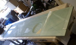
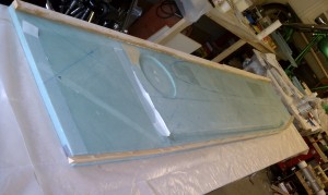
9 May 2011 – Yes! First large glassing step goes well. This took about 8 hours from initial prep to final peel ply. My first exposure to the marathon glassing sessions. As you can see, the inside side of the right fuselage is covered with two layers of UNI (technically UND but we all call it “UNI”) each 30 degrees from the edge, so they intersect at quite a shallow angle (you can see the angled reference lines in each direction that I drew on the foam surface). Once the glass is laid up, then the peel ply is added almost as a top layer of epoxy, with also just enough epoxy to wet it out, but not too little as to steal any away from the glass/epoxy layup under it.
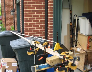
The finished left & right longerons, and the longeron floxed and clamped to the top inside edge of the fuselage side.

•••
Chapter 5 — Step 3 of 4: Installation of Lower Triangular Longeron
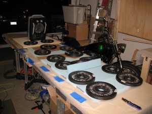
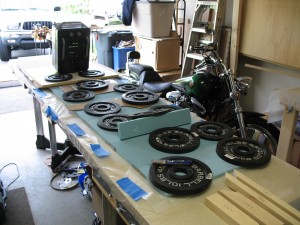
10 May 2011 – Today I attached the bottom triangular longeron (you’ll often see me refer to it as a “stringer” just to distinguish it from the top longeron) to the bottom edge of the right fuselage side. Since the bottom of the fuselage is curved, then of course the stringer must be curved as well. To do this, as per plans, I made a series of cuts approximately half-way through the Spruce stringer. I then drilled holes through the stringer, the fiberglass and the foam to enable holding the stringer in place with medium-sized finishing nails. Once I knew the stringer was lined up correctly and matched the fuselage side’s bottom contour, I floxed the stringer to the fuselage side wall and held it in place with the nails. To ensure the most effective bond with the least amount of excess flox (excess=weight=bad), I weighed the stringer down with weights to squeeze out excess flox, as you see in the pics below.

Another close-up end shot of the stringer—more of the nail placement actually—and a couple close up shots of the trial fitting of the LWX & LWY hard points.

•••
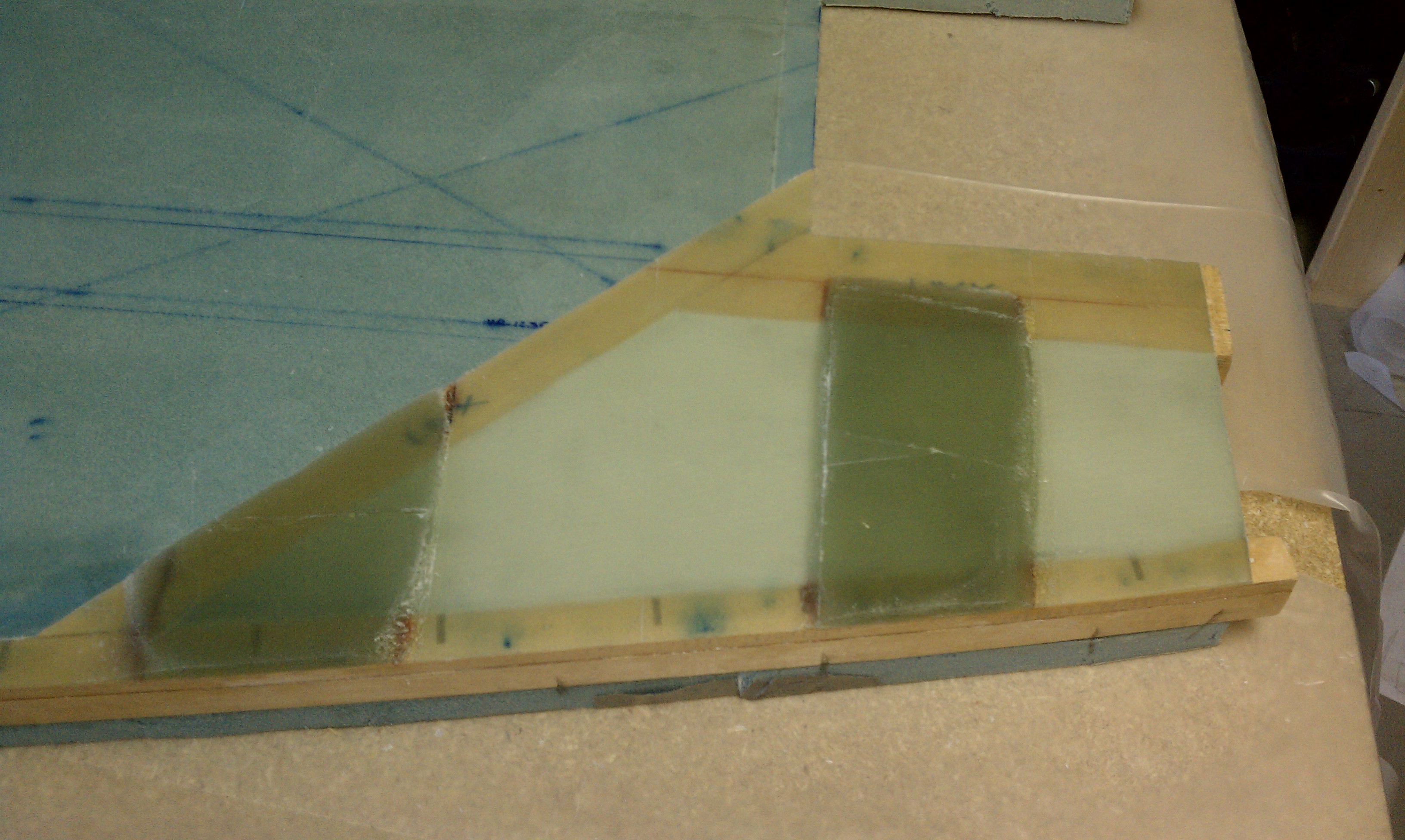
12 May 2011 — The Main Landing Gear Mount Area is bordered by the angled LWX to the front, LWY to the top and a doubled angle-to-angle triangular stringer along the bottom. Although the plans call for Urethane foam (yellow and easily formed) I opted to put the denser, stronger blue Divinycell (same as fuselage sides) in the open filler cavity, in-between all the border Spruce pieces, even though it’s more difficult to work with. You can see a foam wedge already in the fill space with another foam fill piece ready to be micro’d in place into the open space remaining, then the foam fill piece micro’d in place and micro being applied to the top of the foam in prep for glassing. Also, note the flox filling in the gaps that were left by the saw blade, required to bend the Spruce stringer to follow the bottom contour of the fuselage.

The open space of the main landing gear mount area in the lower rear corner of the right fuselage side is filled with foam and ready for glassing with a layer of micro across the foam. I mocked up and test-fitted the F28 Bulkhead doubler near the front of the fuselage side.

•••
13 May 2011 — The entire Main Landing Gear Mount Area at the aft end of the right fuselage side covered with a 6-ply BID layup, with another two separate 15-ply BID pads on top of the 6-ply base layup. Below, the rear seat bulkhead mocked-up.
•••
Chapter 5 — Step 1 of 4 (Left Side)
14 May 2011 — The left fuselage side ready for glassing (the picture is bit blurry).
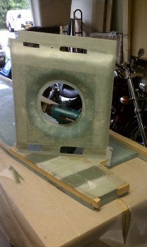
Various shots of the fuselage bulkheads (built in Chapter 4) being fitted in place to their locations on the right fuselage side.

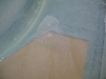
Bad News! A delamination (air bubble) at the RAM mount on the right fuselage side. I drilled the three holes and will use a syringe to fill the air gap with raw epoxy, sealing the gapped fiberglass to the material below and making it one solid entity.
•••
Chapter 5 — Steps 2,3 of 4 (Left Side)
15 May 2011 — Learning from the pain it took to remove the half-dozen individual pieces of peel ply from the right fuselage side taught me to make the process easy by just peel-plying the left fuselage side lay-up with one huge piece of peel ply! Here I’m removing that one big piece of peel ply. I’ve already mounted the top longeron with flox to the fuselage side, and the lower triangular stringer is cut and teed up for mounting as well (thus the reason I’m removing the peel ply at this point). With no control stick depression on the left fuselage side, and having glassed one side already, the left side went significantly faster than the right.
•••
Chapter 5 — Step 3 of 4 (Left Side)
20 May 2011 — Again, learning my peel ply lesson with the right side, I peel plied the entire main landing gear mount area on the left fuselage side. At this point, both left & right fuselage sides are complete up to Step 3. In Step 4 I’ll install the main landing gear mounting brackets.
•••
Chapter 5 — Step 4 of 4: Prep for Fuselage Assembly & Install Main Gear Mounts
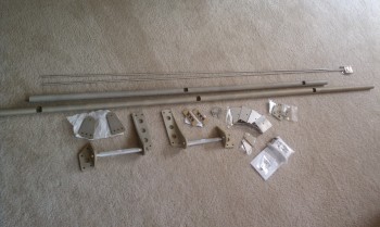
31 May 2011 — Santa (UPS guy) came today! Got my hardware from the Cozy Girrrls! Some nice looking stuff. Still trying to figure out all the pieces and I have to flip through the plans a bit to remember what is going to go where. Right now I need the Main Landing Gear Mount Assemblies (LMGA) and here they are. The instructions on how to put this all together and what goes where is on the large plans drawing Page A5.

