
Ah, time! Just never seems to be enough of it… I had an entire 3×5 card covered –both front & back– with tasks that I wanted to complete today. I got the top 4 completed, with the left armrest wall being the surprise bonus task that I got knocked out . . . read on!
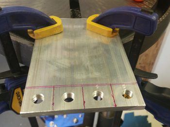
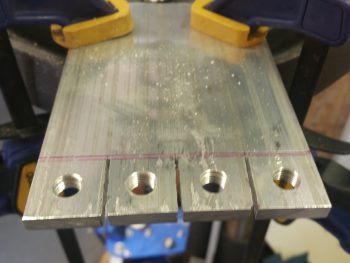
I started off today by marking up the aluminum to cut out the individual hard point blocks for the fuel drain valves.
I had an issue that the only saber saw blade for cutting aluminum that I had on hand was quite dull from the last time I used it. I cleaned it up as best possible and tried it out since I didn’t want to take time out to go pick up some more. Well, the blade definitetly wasn’t optimal, but it was just enough to get the job done.
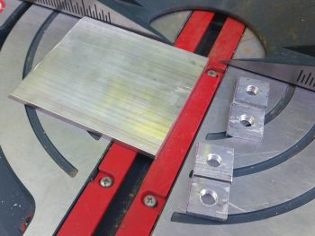
I then pulled out my big miter saw and cut down the line to free all the individual fuel drain valve blocks.
I live in a 3-story townhouse, so I don’t have much room beyond my garage to build. I have a decent side yard, but most of my big tools are in a couple different sheds since I have no room in the garage for all my stuff. I say this because when I go through the trouble of pulling a tool out or opening up those sheds, I want to optimize my time by doing whatever tasks I have on the list with the tools available from the shed. I really do like to consolidate tasks as much as possible because I hate wasting time.
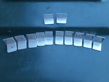
So, with the big miter saw out I cut a bunch of mounting tabs out of 1/16″ 2024 aluminum angle for the right front armrest (a lightweight option idea that I stole from Dave B. after he did all the weight comparisons… thanks Dave!). The tabs are shown further below.
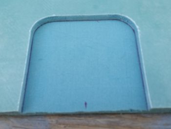
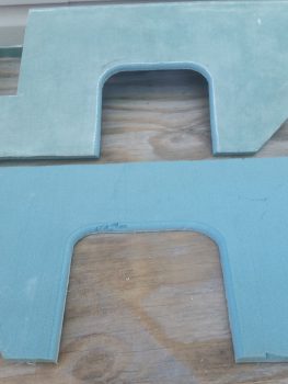
I also pulled out my router table to round over the edges of the lap seatbelt access port. I had planned on doing this, just as I rounded the bottom edges of both back seat armrests, but again Dave reminded me of it last week so I put it on the short task list. Now, the right armrest seatbelt access was good to go since I widened & squared it a bit last week. But the left armrest, which is still in individual pieces, I hadn’t touched since 2012 when I cut it out.
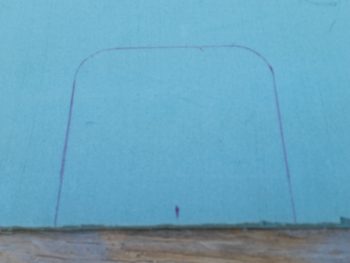
I verified & marked the spot of the left seatbelt bracket on the left armrest. Then I used the right armrest as a template to draw out the seatbelt access port.
I was now ready to cut this baby out!
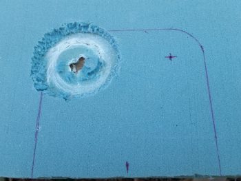
Well, I tried to use a hole saw as I had with the right side. The same exact one in fact. But as soon as the saw blade touched the fiberglass on the back it came off its mount and went absolutely ballistic. It’s done this a few distinct times before, but usually just a minor ding before. No worries. I can assure that this will never happen again with this hole saw because it is no longer with us ( . . . a moment of silent please for the POS hole saw bit).
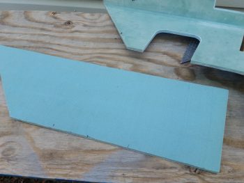
So, I backed up the aft line about a half inch, upped the top line by about a quarter inch, and cut this sucker out! Here’s the result below.
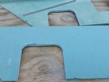
I then radiused both left & right armrests using my router table. As you can see, now just a little bit of extra micro will fill in that gouged foam EZ’ily.
I then cleaned up the right armrest mounting tabs and rounded the corners of the edges that would be protruding out of the wall. I have to say I’m not a big fan of leaving sharp edges about the airplane so I feel like I’m entering the Gauntlet every time I have to do work or maintenance in the bowels of the plane!
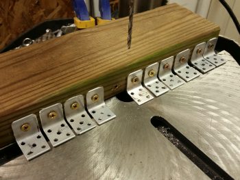
I know there’s a myriad of ways to do this, but I wanted to Alodine these along with the fuel drain valve hardpoint blocks, so I drilled all the necessary holes to flox these to the fuselage sidewall, and mount the nutplates. I started by drilling out the main hole for the screw to go through the tab top into the nutplate. I then used that hole with sheetrock screws to mount the tabs to the side of a scrap 2×4. I then drilled the 5 flox anchor holes into the fuselage mounting side of the tabs.
I’ll note that I specifically wanted these tabs a bit narrow, which meant mounting each nutplate at an angle for it to fit. This angle caused the nutplate center to be pushed out just a hair further from the sidewall by 0.55″ (center of mounting screw). This is a bit more inboard (off the wall) than I would have wanted, but because of the inside filleted corner on this angled 2024, the screw hole is at most 0.1″ farther out than if I had mounted the nutplate parallel to the corner junction, and/or perpendicular to the side edges.
A final point I’d like to make on this is that my more inboard hole placement also has a benefit in that since I’m not glassing the armrest in (as a structural piece), I am not concerned about it’s strength as a structural aircraft member as per the original plans. Thus, now it becomes simply an armrest, so I will not be adding the second ply of BID to it as I had planned to do when I would install it via glassing it in place (again, 2-plies as per plans). With only 1 ply of BID on top, the more inboard the screw (away from the wall), the screw has just a bit more meat to bite into for strength (not huge, but every bit helps).
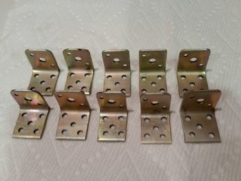
After that, I used a K1000-3 nutplate as a template to drill out all the rivet holes.
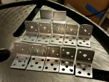
I then counter sunk the rivet holes on the top side to allow for a nice flush fit with the inside surface of the right armrest.
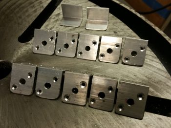
I then Alodined all the aluminum parts I created today, except for two. You’ll not the 2 pieces up at the top in the above pic that aren’t drilled out and that I left blank. Those are spare 6061 pieces that are narrower in depth, and that I may employ at the very front of the armrest where it intersects the panel.
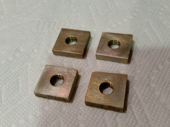
Here are the Alodined fuel drain valve mounting hard points.
And the right armrest mounting tabs.
Tomorrow I’ll be taking off in the late afternoon for a social event, but I plan on trying to knock out as much as I can on the fuel sump build.
Wow, super tidy hard point armrest brackets…if it wasn’t for this blog, no one would know!
Thanks Brother!