
I started off today by figuring out where my heat exchanger air will enter from the main air duct into the upper heat exchanger duct . . . which of course is the inlet duct for the heat exchanger. After figuring out where my perimeter “no-go” areas were for both the main air duct and the underlying upper/inlet duct [as it’s positioned in this pic…look upper left] I marked off the inlet hole.
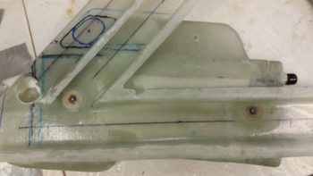
I then drilled the center mass of the marked hole out with a 1-1/4″ hole saw bit.

I then used a sanding drum on my drill to shape the rest of the hole. This inlet hole is a fair bit larger than the rest of my standard sized 1.5″ duct area since with the height of the duct at only 0.75″ tall, the air inlet ramp created by the opened valve –to divert the incoming air into the heat exchanger– will be longer and flatter, requiring a bit more open hole area for the equivalent amount of air to flow through.
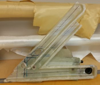
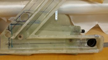
Here’s a shot of my current left side wall mounted GIB area ductwork, with the heat exchanger and the GIB low eyeball vent mounted as well. If you look closely, you may note that I chopped off 0.4″ of the aft end of the horizontal duct (bottom right of pic), and moved the hole forward 0.4″ to allow moving the low eyeball vent forward for clearance with the 2 oil lines.
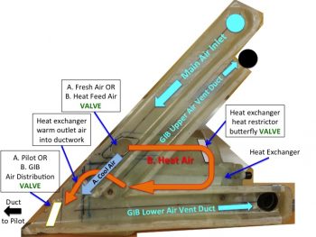
Also, for a bit better understanding of what I’m doing here, I took the pic above and turned it into a quick labeled diagram of all the major parts of the ductwork & oil heat system located in the GIB compartment. Yes, it’s not the best graphic…. and not to sound overly snarky, but my goal is to get this airplane finished, not to build stunningly beautiful charts!
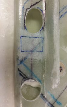
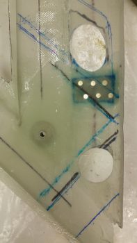
Below is a closeup shot of the 2 heat exchanger-related holes in the main air inlet duct. The top one is the one I just created, and again which allows the outside ram air to flow through the main inlet duct and into the heat exchanger –WHEN THE HEAT AIR VALVE IS OPENED. Otherwise, if the valve is closed the air simply passes over the valve and continues on its merry way into the ductwork both in the GIB area and forward to the pilot’s seat area.
The lower opening is strictly used only when the air is flowing through the heat exchanger and is the inlet for warm air to flow from the heat exchanger into the ductwork system. An important note is that the valve that diverts the air to the heat exchanger lies in-between these 2 openings. Thus, when the valve is open and the air is flowing into the upper opening, it stops any air (or the vast majority of it) from passing into both the rest of the ductwork system (since it’s being diverted into the heat exchanger) or into the lower opening (which will have warm air exiting out of it from the heat exchanger into the ductwork).
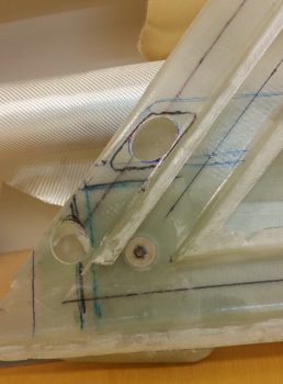
You might be wondering about the lower air opening when the heat exchanger is not being used for heat, or stated another way, is not in the “on” state.
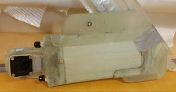
Well, some air will certainly flow into the heat exchanger in the opposite direction through this lower hole. First, the hole in the main air inlet duct (on the left side) will be covered by the valve plate so no air can flow backwards into the main air duct from the heat exchanger. Then, if you look below you’ll see a bright shiny lever on the side of the heat exchanger’s upper duct, which is the inlet air duct from the upper hole to the heat exchanger. This lever controls the heat restrictor butterfly valve. When the heat exchanger is not being employed to produce heat, this valve is closed, and thus also restricts any air from passing in the reverse direction through the heat exchanger.
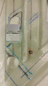
Here’s a shot of what the GIB is more likely to see sitting in the back seat. This is a good shot of how the heat exchanger will look in its final constructed state. I just floxed the lower outlet duct (on the right) onto the heat exchanger. Once I finish constructing the butterfly valve (I just ordered a 1/4″ 2024 rod from ACS) I will also flox the upper inlet duct into place atop the heat exchanger. On the left side of the pic you can of course see the GIB lower eyeball air vent.
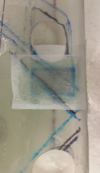
I then started work on prepping the main air duct glass for mounting the Fresh Cool Air OR Heat Feed Air Valve into place (I’m going to have to come up with a standard name for these valves!). I sanded the interior duct glass where yet another 0.5mm aluminum reinforcement plate will be glassed in for mounting the valve assembly.
I cut out the 0.5mm piece of aluminum (from my German consumables stock!) for my reinforcement plate and then wet floxed it into place with one ply of BID over it.
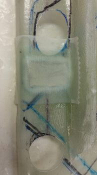 Although I had made up a minuscule amount of epoxy for the layup above, I still had a decent bit left over. So I quickly moved onto my next layup –earlier than I had planned– and laid up 1 ply of BID on the opposite side of the aluminum reinforcement plate, this ply of BID also glassed in place merely for reinforcement purposes.
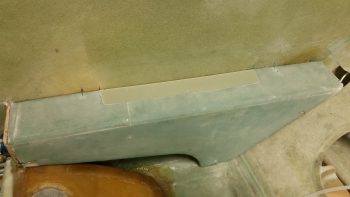
I then started working on the G10 Garolite lid for the right GIB armrest storage pocket. After I trimmed and sanded it for a bit, I was able to set it in place on the very slight lip that I created on the inside edge of the armrest storage pocket cutout.
By this point my glass had cured on the valve mounting reinforcement layups, so I pulled the peel ply and cleaned them up. I then spaced out & drilled 6 holes for countersunk rivets through the lower valve assembly plate and duct wall. I then floxed the lower valve assembly plate into place and riveted the 6 rivets into place.
Tomorrow I’ll continue my quest to finish the air ductwork and heating system, as well as get as much installed in the GIB area as possible before 1 August.