
Yes, it finally happened guys! I’m back in the shop. I have to tell you after being out of it for a couple weeks I had to get my sea legs back as I was suffering a little bit of analysis paralysis on what to start in on first. Luckily I had made my task list up the other morning so I just grabbed it and started at task #1. That saved me from spinning my wheels and wasting time.
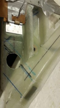
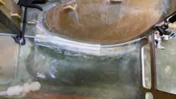
I started off with a bunch of small layups, thus the title of this blog post. First off, I sealed off the significant gap between the fresh air/heater air valve (Valve #1) plate and the duct sidewall. I taped off the valve plate with brown packing tape (I’m out of clear) and kept the valve plate up flush to what will be the back wall of the duct by taping it to a 12″ ruler that I laid across the other duct back wall edges as well.
I then added some flox along the edge of the taped up valve plate and added a ply of BID. I then peel plied it.
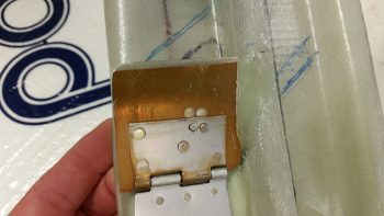
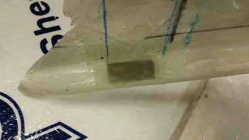
Since I used fast hardener in my epoxy, here’s a shot a few hours later when I pulled all the tape and cleaned it up. The top pic shows the valve in its normal closed state (fresh air through the ducts) while the bottom pic shows the valve open and the side edge seal at work (diverted air to heat exchanger).
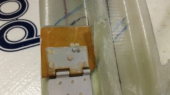
When I created the valve plate edge seal above, I also laid up a ply of glass on the inside of the bottom horizontal duct edge and peel plied it. In addition, I cut a small rectangular reinforcement piece of 0.5mm aluminum and floxed in place on the outside bottom edge of the duct and covered it with 1 ply of BID. This too got peel plied.
These layups and aluminum plate will serve to reinforce the installation of the PIC/GIB air distribution valve (valve #3) when I install it.
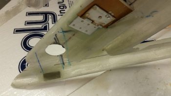
Then, for the first time, I test mounted my Matco parking brake valve on and thru the finished & painted forward NG30 cover plate. Besides wanting to ensure the valve fit and clearance for the operation of the lever arm, I also needed it in place to determine the length of the parking brake control lever cable to the pull T-handle.
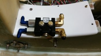
I played around with the control cable length for a while and estimated as closely as I could the final position of the parking brake pull T-handle. Once I decided on the parking brake T-handle location, I cut the entire cable to length, and then cut the outer cable sheath to expose the last 6″ or so of the control cable wire.
I then cut the 1/4″ Nylaflow control cable conduit and roughed it up with sandpaper. I also sanded all the contact point areas along the path of the 1/4″ Nylaflow conduit along the left side lower corner of the nose wheel well cover (NB) and along the bottom edge & side of the left NG30 plate.
I then 5-min glued about a 6″ length of the Nylaflow into place along the bottom corner of the nose wheel well cover (NB) and let it cure. After the 5-min glue cured, I then micro’d around the conduit and laid up a prepregged ply of BID 1.5″ wide x 9″ long.
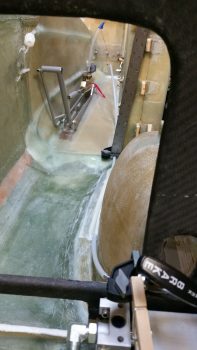
I then peel plied the edges of the initial parking brake control cable conduit layup.
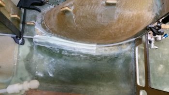
Since the path of the parking brake control cable conduit will require a sort of an “S” curve on the lower aft area of the left NG30 plate, I decided to secure & glass it in place in smaller, bite-sized sections in order to minimize my chances of any given section pulling free or going haywire as I set each segment in its correct spot.
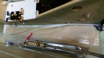
I uploaded the above pics here side-by-side to give you somewhat of a panoramic view of the entire parking brake control cable run from T-handle to parking brake valve. Again, this is on the list of things needing done before I close up the top of the nose and access to these areas that I’m currently working is greatly restricted.
I have to say that there is often a lot of research, planning and design time spent that I don’t really report on. After I did all the above, I spent a good half hour assessing and reviewing the placement and configuration of the two pilot seat thigh support ribs. Moreover, I finalized the details on aft side of the pilot thigh support, which unlike most Long-EZs will be modified to incorporate a triangular duct across the aft edge for the right foot heater vent.
Tomorrow my next door neighbor is having a Labor Day cookout. Since I’ll be over at his place for most of the afternoon and evening, it will be yet another light build day. But I do plan on getting as much done as possible tomorrow on this internal cockpit stuff.