Chapter 23 – Baffles: A new look

I started off correcting a minor alignment issue on the right aft lower baffle that was causing a bit too much of a gap between the inner CF cylinder baffles and the front edge tabs of this baffle.

Simply put, the outboard mounting tab was too far forward and thus pushing the aluminum baffle away from the cylinder and causing the inboard gaps.  The mounting tab needed to come aft about 3/16″, which meant re-bending it.  Which of course meant bending it back straight first.

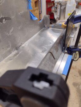
Once back straight, I needed to trim about 0.150 off the top to allow using my Mini metal bender since it only has a 1″ depth on the deep side (3/8″ on the other side).

I then re-bent the forward mounting tab.  It’s hard to gage exactly when bending this aluminum sheet, and definitely got close enough… optimum would have been about 0.030″ closer to my line, but this will definitely meet my requirement.

I then set the aft right lower baffle back into place to check the fit along the front edge.

With the front side gaps good, I then proceeded to cycle through getting the inboard edge and the starter opening dialed in.  That took a good half dozen times removing the baffle and taking a trip to my Dremel tool station.  I eventually got it, and barring a few very minor touch-up trims, the aft lower right baffle is now fitting rather well in its location.

Here’s a closer up view of the front side edge of the aft lower right baffle.

I then went back and did some minor tweaks on the left side, and here it is set into position as well.

And a shot with both left and right aft lower baffles in place… remember, they’re not mounted so these positions aren’t exact yet.

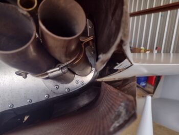
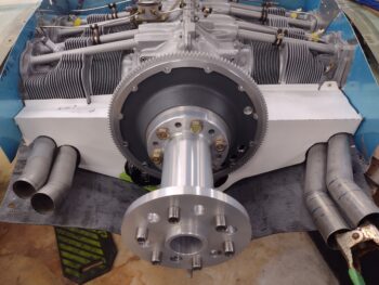
And a shot of the lower, intersecting baffle skirts around the alternator and starter.

Speaking of the alternator, I had to buy a new, longer bolt since I want to mount the alternator-to-starter reinforcement bracket on top/aft/outside of the baffling.  Not only will this allow the baffling to have a more comfortable clearance with the flywheel pully bracket, but will also help secure the intersecting baffle edges together.

With both side aft lower baffles looking good, I then pressed forward with finalizing the aft vertical baffles’ configurations.

Here we have the alignment mark on the aft left vertical baffle with the aft edge of the lower baffle (in the background).

I then bent the left aft vertical baffle on the metal brake to create a tab facing 90° outboard…

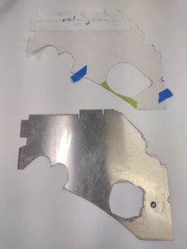
As can be seen here.  I then transferred the fitted cardboard tab that I cut out last week to this aluminum vertical baffle tab… and then trimmed it.

Now, there is a bit missing on the bottom which I will fill in when I but the reinforcing 90° angle bracket on the “back” side (technically forward) of this corner.

I then repeated the process for the aft vertical baffle on the right side: creating the 90° outboard-facing vertical tab, then trimming it to shape.

The right side too will need a minor addition on the bottom.  Again, that will attach to the reinforcement right-angle piece that will get riveted into the corner.

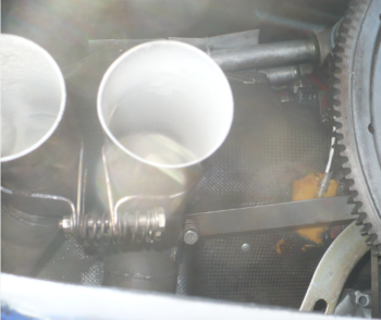
Here we have a shot of the current baffle situation.  I plan on getting these things mounted soon, then getting the flexible baffle seals mounted to the edges of all the aluminum baffle walls to finish the job.

Pressing forward!


Chapter 23 – Baffles ‘bent into shape!’

I started off today with 2 tabs left to bend on the front of the right lower aft engine baffle. Since these tabs are situated on the interior of the front edge, with an obstruction on both sides, I needed to figure out how to get the very useful bending tool into that interior edge.

My solution was to simply cut off a 3.6″ wide section of the 12″ wide metal bending tool.  This would allow me to get the wider outboard tab bent downward 90° and subsequently out of the way for then bending the narrower inboard tab down 90° as well.

I drew my cut line and grabbed my cutoff grinder and got to work.

I will say that this is a robustly thick tool as it took me a good 15 minutes to get a nice cut all the way through… but persistence paid off and here we have the 3.6″ section of the metal bending tool, or what I’ve now dubbed the “Mini metal bending tool.”

I then clamped the right lower aft engine baffle inverted on the workbench just so that the edge was hanging off, and then used the new Mini metal bending tool to bend the tab downward (up in the pic) 90°.

Here’s the end result of that bending action:

I then did the same thing for the inboard interior tab (right side in below pic) and bent it downward 90° as well.

Thus, here we have the right lower aft engine baffle with all the required tabs bent into their respective positions.

And the same for the left lower aft engine baffle… all tabs bent as needed.

I also spent a good 20 minutes on the first round of trimming the required areas I had annotated before, to get this baffle segment to fit in place correctly (I’m sure there will be more trimming sessions no doubt).

Before removing the alternator, I figured out where my safety wire runs were going to terminate.  I then made a mark at each of those 3 positions.

And then drilled those 3 holes with a small drill bit to allow for safety wiring the 2 alternator bolts and also the bolt securing the inboard bracket for the left shelf & skirt baffle.

And with that, I called it a night (I’m also slowly cleaning the rust off my plasma cutting table metal components in prep for using it in the near future!).

Chapter 23 – Bending aft baffles

Today I started down the road of bending up the aft lower baffles to get them fitted onto the engine and hopefully put the engine baffles in my rearview mirror in short order.

In addition, I’ll note that I wasn’t liking my options thus far on how to secure the exhaust pipes —both to each other in pairs and to the engine to ensure none depart out the aft cowl opening into the prop, if there ever were a crack or a break— so I took another hard look at the instructions that came with the cowlings from Mike Melvill.  It was at this point I decided to mimic closely what he did and press forward in a different direction on my pipe brackets… Melvill style! (more to come on that in the near future).

I started my baffle bending endeavors by deciding what order I needed (or could) bend each baffle without “painting” myself into the proverbial corner of blocking the ability to do a certain bend by having done another preceding one that prevented access to it, or at least making it exponentially more difficult.

The first bend for both left and right aft lower baffles was the big 90° one on the metal brake.  Here we have the aft lower left baffle ready for bending . . .

And post bend.  Honestly it took more time marking the bend line and applying the protective tape then the 30 seconds to bend the darn thing!  I then repeated the process for the right side baffle.

Not shown in this post is the 2 front tabs on the forward side of the left aft side lower baffle that I bent downwards 90°.  These tabs will get RTV’d to the CF cylinder fin baffles to seal this lower baffle to the engine.

As you can see, the 2 outboard tabs: top and front (“shelf and skirt”) have not been bent yet.

I also checked the fit down below with both the exhaust pipes and the alternator.  I could tell by the alignment with the alternator that the outboard top corner of the baffle needs to come down about 1/8″ while the entire baffle needs to be rotated CCW to do that.  That will require some judicious trimming around the inboard baffle edges where it meets the cylinders… trimming notes already annotated.

I then mounted the CF 180° air induction intake tube to do a fit check with the baffles.  Here I’m holding a piece of cardboard up against the back apex of the air induction tube to check clearance with the new lower baffle.

It may be a bit difficult to see the aluminum baffle…

Which is why I grabbed these progressive shots below, to show the relationship between air induction intake tube and the bottom edge of the lower baffles.  I’m not worried at all here with clearance because I’m going to glass in (ok, CF) a mini-bulkhead wall into the lower cowling that will sit just aft of the air induction tube and stop at a height about 1/2″ below the aluminum baffle skirt.  Clearly the sealing material on the bottom side of the aluminum baffles will then seal against the top edge of the bulkhead (aka “aft bottom cowling reinforcement rib”).

Beyond the big 90° bend on the right side aft lower baffle, I did a bit of the opposite as far as the perimeter tabs are concerned:  I did the one upward bend along the front edge, which is the tab where the baffle gets physically mounted to #2 cylinder via a screw.  I also bent the 2 outboard tabs (top: down and front: forward).

Just as on the left side, I’m using a sheet metal bender that is common among HVAC guys for working sheet metal ducts.  If the material is clamped properly, this basic tool is quite handy and works a treat.  No issues so far (knock on wood!).

Here we have the top tab bent down 90° on the outboard side of the right aft lower baffle.

And then the front tab bent forward 90° on the outboard side of the right aft lower baffle (note the upward bent baffle attach tab on the right side of pic).

Although all taped up to prevent any untoward scratching, I grabbed this shot of the right aft lower baffle.

It was getting late and Jess was over making dinner, so I called it a night.  Tomorrow I’ll bend all the remaining baffle tabs and then dial in each side to fit.  If all goes well I might actually do the final install of the alternator with belt tensioned correctly as the left side baffle gets installed.

Chapter 23 – Engine Turned Baffles

Today I finished Engine Turning all the major baffle sections on the engine that I’ll be doing.  Here we have the lower left aft baffle just completed.

I set the lower left baffle in its approximate place and then prepped the lower right aft baffle for Engine Turning.  The lower right baffle is patient zero—the one that had the scratch that drove this entire Engine Turning craze!  As you can see in the upper right hand corner where I buffed it out.

A few hours later: Voila! the lower right aft baffle is complete with its Engine Turning as well.

And another shot of the all the major aft-facing baffle walls Engine Turned.

As I note in the video, using the method I used the 6061 aluminum didn’t turn out as spiffy keen as the front 2024 baffle panels.  They still look very presentable in my opinion, but they certainly show a lot more rings in each individual circle.  That being said, the offending scratch is virtually gone and these things are still functional… and will be somewhat obscured in the engine compartment, so I’m done worrying about them and pressing forward!

I documented my Engine Turning journey in this mini-documentary (haha… ok, it’s just a video!).  Enjoy!

Next I’ll be bending the aft lower baffle segments to get them mounted into place.  The upcoming “wings” on each outboard side of the upcoming installed lower “shelf & skirt” baffles may very well get Engine Turned as well, but that’s as far as I’m going on the engine baffles…

But how about those outboard CS spar Titanium firewall sections?  Hmmm?


Chapter 23 – Engine Turning Baffles

As I get back onto my build and focus on getting the airplane completed, along with that I also have a goal to get all my shop tools online, maintained and dialed-in as they should be.  Obviously having an immediate job that requires their use makes it easier to focus on a given tool.

And thus it is with this week’s “power tool of the week,” to focus on: my standing drill press.  I started this endeavor a couple nights ago as I scrounged around a couple of hours off and on to find the parts box.

The next day I spent well over 2 hours cleaning and removing a good bit of the rust off the drill press, especially the chuck which was a solid chunk of rust after going through the hurricane back in 2019.  By the time I got the drill press to my shop (from my old hangar) back then, it had all the handles, belts, etc. in one box, and the chuck in a bag of solvent to remove the rust (in the garage).  I then never assembled it or used it, and am just getting to it now.

After putting a nice scratch on the lower right engine baffle as I was drilling a relief hole, I was assessing my best options to remove the unsightly scratch.  It turns out that as I was on the COBA forums earlier reviewing posts on engine baffles and exhaust systems (aka “What would Klaus & Marc Z. do?”), someone posted a shot of their firewall that they had just finished Engine Turning (or “jeweling”).  This was pre-scratch so I simply filed it away in my mind as a point of interest.

Someone else on that forum thread placed a link to a pic of the Spirit of St. Louis, which is a great example of engine turning on the cowls.

Post-scratch:  To be clear, I like the nice smooth look of aluminum baffles around the engine.  But I was going to have to do something to remove the scratch, and clearly that baffle segment wasn’t going to look the same after the scratch was removed… and would very well likely need the entire baffle buffed out to blend the scratch in.  After spending a good couple of days blending the paint in on Guy Williams’ Long-EZ as I repaired its winglet, blending anything at this point was not something I wanted to engage in.  Thus, Engine Turning became my answer to resolve the scratch issue.

After a good round of research on how folks were doing it, I then tried my hand at Engine Turning on a scrap piece of aluminum…. looking pretty spiffy to me!

I then decided to Engine Turn all the baffle surfaces that face reward on the engine and that would be somewhat visible when looking into the cowled bird.  I started my no-kidding Engine Turning adventures on the front left baffle segment and got this far before calling it a night.

I finished the first big top forward baffles today… here we have 2 of the 3 front baffle segments Engine Turned.

Jess was sweet and cooked me dinner over at her place tonight, but before I left to go over there I was able to finish the last segment of the front engine baffles.  Here are all 3 front baffle segments Engine Turned.

Tomorrow I plan on getting the 2 aft lower baffle segments Engine Turned.

Chapter 23 – Aft right lower baffle cut

Today I cut the right aft lower engine baffle out of 6061 aluminum.

Unfortunately I dove in without drilling the relief holes at the bend edges, so I had to do that after the fact on a couple of them.  Over towards the mid-right side as I was coming in from the edge the drill slipped and went across the face of the baffle, placing a decent-sized scratch on it for a few good inches.  Soooo, I’ll have to see if that buffs out.  If not, I think I have a backup plan to eliminate the scratch.

I then headed into town to pick up a sheet metal bending tool from Harbor Freight, but alas, they were sold out.  I ended up grabbing some Thai food with Jess, and then headed home with a handful of stuff from HF, but not what I had ventured out for.

After doing some online searching, I ended up ordering the sheet metal bending tool off of Amazon.

I then spent a few hours doing some research on my next steps, as well as gathering up (read 45 min looking for!) all the pieces/parts to get my drill press back online —which I haven’t used since I moved into this shop nearly 5 years ago.

A significant milestone in cutting this thing out, now to get ‘er installed.  More to come!

Chapter 23 – Big baffle push

Today was all about moving out on the baffles.  In fact, my goal is to have the baffles COMPLETE by this coming weekend.

One thing I’ve been pondering for quite some time now is how exactly to work the sides of the baffles:  my decision being between leaving the side baffle segments long and extending them aft, or creating little mini-walls on the outboard aft side of the aluminum baffle segments to close off the air coming along the side.

I decided on the latter.

In doing so, I measured and marked where these mini-wall baffles would be, then marked those positions on the upper cowling.  Using contours of the inside upper cowling, I then made some initial baffle mini-wall templates and taped them into place on the left and right sides.

I then put the top cowling in place, used a shop light to check the mini-wall baffles vs the top cowling sides, took the top cowling off, trimmed the mini-wall baffles, then repeated the whole process….  a good number of times.  It’s an iterative process!  

But I finally nailed down the configuration for both the left and right side mini-wall baffle segments, which we have right here:

Before doing any cutting or brake bending on the side baffle segments, I wanted to have the no-kidding position of each lower aft shelf and skirt baffle segment in place first.

I started with the left side and traced the template onto the 6061 aluminum sheet.

It may be a little hard to see here, but the lower aft left baffle segment is ready to be cut out of the 6061 aluminum sheet…

Which I did next.  Here we have the left lower aft shelf and skirt baffle segment cut out and ready for clean up and then some bending on the brake.

I then placed the template for the right lower aft shelf and skirt baffle segment on the 6061 aluminum sheet and traced it out.

Here’s the lower aft right baffle segment ready to be cut out of the 6061 aluminum sheet.

It was getting late so I decided to call it a night and will cut out the right side lower baffle tomorrow.  I also plan on doing a good bit of bending these aluminum segments on the metal brake as well.

Chapter 23 – Securing exhaust pipes

First off, I’ll regale you with a quick story: Fall 2013 and I’m in the middle east.  I ask Mike Beasley where he bought his exhaust pipes from, and he sends me the link to Custom Aircraft Parts with the part number he bought.  I send an email to Clinton detailing my bird’s cowlings, engine, etc. and he spits out the same part number as Mike’s. I know realize the key piece of information that I added to my email that tipped Clinton off to that part number was “Feather Light” and am almost certain that is why I received the pipes that I did.  The actual key wording that should have been focused on was “Mike Melvill’s carbon fiber cowlings“… because although Feather Light made the Melvill CF cowlings, they were nowhere the same as the stock Feather Light cowlings (I’m guessing those were close to the Task cowlings, which I’m pretty sure is what Mike has).

I figured all this out from the multiple comments on the COBA forum while I was researching baffling and exhaust pipe configuration stuff.  I should have opted for the Cozy exhaust pipes that have a significant S-curve up and then straight rearwards immediately aft of the cylinders… not the gradual curve that Mike’s and mine have, although I’m having to significantly modify mine.  If I knew then what I do now, I would have demanded a swap-out for different style (part number) pipes.

Ok, part of my research was Klaus discussing that having your exhaust pipes separated about 1/2” apart is best since it keeps the vibration/harmonics/pressure waves of the pipes and exiting exhausts from affecting each other.

Now, back to Custom Aircraft Parts for a moment… if you look (closely) at Mike Beasley’s exhaust pipes you see a rounded “W” looking clamp that secures the pipes together (Dave Berenholtz and many other canards have these too).
[Also note the center crankcase vent tube in between the pipes… it comes into play]

Here’s a look at the bracket from Custom Aircraft Parts.  The PRO is that I’m certain that it’s well-made and it does the job.  The CON is that one pair costs $275, and that’s without shipping.  Clearly to do both sets of pipes we’re talking around $600.

That dog will NOT hunt!  Sorry, I’m not paying nearly $600 for these brackets, nor am I going to pay around $300 for one bracket pair.

I’ve already ordered the stainless steel from McMaster-Carr to construct a bracket pair for the RIGHT side, and the 1/2″ round tubing I’ll be using to create a securing brace for both sides.  Moreover, I also ordered 321 stainless steel “P” clamps (AKA bare Adel clamps) for the LEFT side, all for just over $60 bucks (including tax and shipping).

Taking Klaus’s words of advice into account, I then modeled up a set of brackets in Fusion 360 CAD to test out his 1/2″ gap configuration.

I then 3D printed a narrower width version (0.4″ wide vs 0.75″) of the brackets to save both printing time and plastic.  Here’s the result:

I then test-fitted the brackets onto the left side exhaust pipes.  The 1/2″ gap between the pipes drives the outboard pipe out too close to the upper cowling wall, so I’m going to have to pass on his advice and go the more standard method that is seen in most canards (pipes nestled together).

I then cherry picked through my stock of Adel clamps to find one that fits the 1.75″ dia. exhaust pipes spot on, which is the -25.  This was merely a test fit as the potential issue here if I were to use an Adel clamp is that they are aluminum (from ACS) and their ability to fend off the intense heat of the exhaust pipes is —in my book— suspect.  They do make stainless steel versions of these style clamps, which is what I ordered from McMaster-Carr.

Although I only have one clamp installed below, in the final configuration I’ll have one on each pipe, mounted back-to-back and secured by a 1/2″ brace that will serve to keep the exhaust pipes in position during normal ops, and also keep any pipes from exiting the cowling should either of them crack/break free.

As a point of reference, here is a shot of Klaus’s exhaust pipes… note the P clamps securing his pipes.

Finally, the reason I’m not using the “P” style clamps on the right side exhaust pipes is simply due to the crankcase vent tube that will nestle in between the pipes to create the lowest profile of this grouping as possible.

And with that folks, I’m calling it a night.


Chapter 23 – Pipe monster returns!

Last night I got my air compressor oil change and maintenance tasks finally completed, with some test runs to ensure the pressure valve was working correctly.  All looked good.

I also took out the oil heat sump street fitting with standpipe to do some “spot welds” on it just to ensure it’s physically fit for duty in the engine.

Today I got back to work on the aft/lower engine baffles by putting the thick paper templates back in place.  I made notes and trimmed the templates in various spots as I worked to dial in the final configuration of the lower baffle “skirt.”

After removing the aft/lower baffle templates, I figured it was time to add in the last reinforcement piece to the “Melvill” baffle bracket that mounts to the aft right side of the engine.

I scrounged around for the best piece of scrap left over from the VANs baffle kit, made up my tape template on the bracket and then transferred it to the scrap aluminum piece.  I then cut out the reinforcement plate and bent the tabs on the metal brake.

Here we have the reinforcement tab riveted to the Melvill baffle bracket, with the bracket reinstalled on the engine.

And yet another lower view of it.  Another task, of a myriad left to do, completed.

I then mounted the top cowling to capture all the tasks I need to finish on that, and take a hard look at the final exhaust pipes configuration.  Assessing my exhaust pipes once again, I’m still convinced that these are the wrong pipes for my setup: a case where I (the layman) am correct, and the vendor is plain wrong.  Which at this point means nothing now other than working the problems out.

After analyzing the exit positioning of all the exhaust pipes, I came to the painful conclusion that I’m going to have to once again cut the left outboard pipe to angle it both inboard and down a hair —so that it nestles in very close to the inboard pipe in its position below.

The right side exhaust pipes will be workable, with the only drawback being the position of the aft final bend in the pipe… which happens to be right where I need to trim them. The cut will either have to be a bit further in than I want (~2″ inside the cowling), or I’ll have to live with the aft pipe openings pointing outboard much more than desired.

Pressing forward…

Chapter 25 – Fixing Guy’s Long-EZ

Over the past week I’ve been involved helping my local Canardian buddy, Guy Williams, fix his Long-EZ that was damaged during its annual condition inspection, when the A&P pulled the batteries out of the nose without it being lowered first… Oops!  And yep, up it went on its backside.

The nearly horizontal prop got a ding on one end, which Guy removed, boxed up to send to Joe Person for repair, and replaced with a spare wooden prop.

The lower aft winglets were next on the list of damage, with the right getting off fairly easy while the left took the brunt of the impact: cracking the tubular taillight housing, these being added to the bottom of the lower winglets by original builder Frank Tifft.

Here’s the right lower winglet with some minor cracks, which I filled both internally and externally with micro and flox.

Again, the damage to the left lower winglet was much more extensive and required sanding off the paint to expose all the damage.

Apparently neither Guy nor I got a shot of the left winglet’s damage, but my first task was to get all the cracked “jigsaw puzzle” pieces micro’d/floxed back into place and the original shape reestablished.  I then did a 1-ply UNI wrap layup to secure the reassembled structure to the existing lower winglet.  That did the trick and it was plenty strong with minimal added weight.

Also not shown was the remaking of half the top and the complete bottom taillight standoffs that are located at the upper and lower side of the light bracket at the screw mounting positions.  After creating templates of the right light assembly, I made the new taillight mounting standoffs out of 1/8″ thick G10 phenolic and floxed them into place.

After an overnight cure on mounting standoffs, I slathered up the lower left winglet with micro, and cheese grated it about 3-1/2 hours later.

The following day I sanded down the micro to its final state, and then applied 5 epoxy wipes as per the Corey Bird finishing method.  We then let that cure overnight as well.

After sanding down the epoxy wipes and blending that into the existing winglet paint, I then hit the repaired area with a couple coats of primer.

I then shot the lower left winglet with some color-matched Nasson paint that we picked up at Napa Auto Parts.

The blending is always the hardest part when you’re repairing a smallish area on a much bigger painted surface.  Even though when I shot the paint I kept peeling back the tape to expose more of the original surface, there was a bit of a hard paint line that was distinct between the old and new paint.

I told Guy we could let it cure and see how the paint levels out, or try to blend it more.  He wasn’t too keen on the distinct line between old and new paint, so I very carefully went sanded the junction line, prepped the old and new paint surfaces and reshot the yellow paint to blend it in more.

Here’s the result.  It’s very difficult to see any difference on the inboard side of the winglet.

Admittedly, I am NOT a master painter, and the outboard side of the winglet looks really good, albeit the blending did leave a hair flatter surface towards the front lower side of the winglet that can be seen if you’re looking more critically at the paint.

In the pics above and below the taillights have been successfully reinstalled (note the light brackets were stripped, primed and repainted as well).

As both Guy and I quipped at the end of our repair effort: Good enough for government work.  Time to get this bird back in the air! … and for me to get back to getting my bird in the air.