Chapter 23 – Exhaust pipes cut!

I’m happy to announce that, at least as far as this Long-EZ build, today is a rather historic milestone.  After well over a year and a half of working my cowling vs exhaust pipe issues, both of these have been essentially solved.  Especially since today I finally trimmed both sets of exhaust pipes to length!

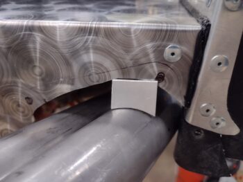
Ok, starting out I pulled the crankcase vent tube Batman cradle/insert Version 2 off the 3D printer and test fit it on the pipes.  There was still just a hair too much play at the bottom of the “V” so I added 0.012″ to each side of the gap and reprinted this insert.

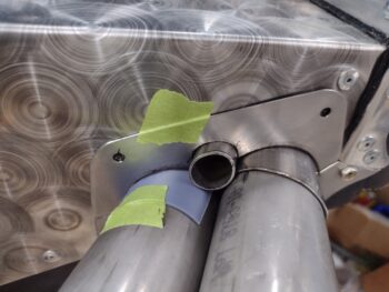
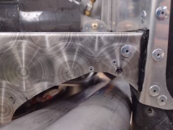
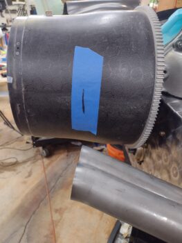
Here’s a shot of the approximate location of the 2 aft cradles, which will secure the crankcase vent tube in between the 2 right side exhaust pipes.  The single pipe “saddle” will be on the outboard pipe at about the very right edge of the pic below.

I wanted to trim the exhaust pipes after I had a chance to get the exhaust pipe brackets welded up by my Über-welder buddy James, but I know he’s busy and I wanted to get these pipes cut.  I doubt that the bracket configurations are going to change more than a few thou one way or the other, so I’m pressing forward.

I started on the left, port side.  Now, what I’m dealing with in trimming these exhaust pipes is that I’m not just cutting the ends 90° in the vertical and 90° in the horizontal… not that that’s not exactly what I would prefer to do!

As I’ve noted before, since these pipes have a final curve outboard when looking from the top, and the upward angle of the pipes as they approach the aft cowl opening looking from the side, leads me to leave a bit more pipe on the exit top edge and angle the exits inboard in an attempt to shoot the exhaust straighter aft (vs up) and inboard towards the prop hub.

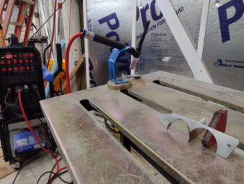
I took a while —using a measuring tape, yardsticks, plumb bob, and laser level— to dial in the cut angles that I wanted (pic 1), at which point I removed and cut the outboard pipe (pic 2).

With the outboard exhaust pipe to my desired angles, I then used it to verify the cut line for the inboard left exhaust pipe.  I then removed the inboard pipe and trimmed it to length.

Here we have both left exhaust pipes cut and trimmed to their final length and exhaust angles.

Before moving onto the right side exhaust pipes, I quickly mounted the bottom cowling to verify that the left side pipes were good.

I also checked the distance between the end of each left side exhaust pipe and the aft edge of the lower cowling: about 1.2″ for the outboard pipe and 1.4″ for the inboard pipe.  I discuss the difference from the left side in the regard as compared to the right below.

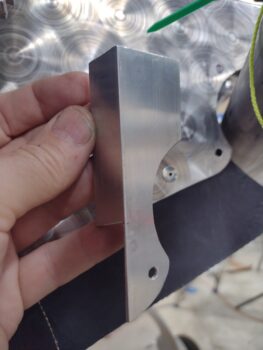
Also before I started on the right side exhaust pipes, I grabbed some coffee from the house and Version 3 of the crankcase vent tube Batman cradle/insert off the 3D printer. Yep, I think this one is the dawg that will definitely hunt!  I’ll start working my plan to machine these saddles/cradles/inserts up on the mill.

On the right side exhaust pipes I pretty much followed the same exact process as I did on the left side: verify the final length and angle of each pipe before marking them for trimming (pic 1).  And then removing the outboard pipe to trim it first (pic 2).

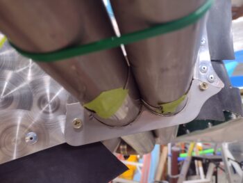
Here we have the right side exhaust pipes —and thus ALL the pipes at this point!— trimmed to the length and angle to get the best exhaust flow out of the cowl as possible.

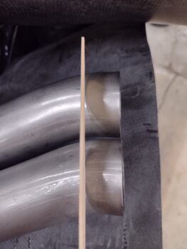
Here’s an initial shot of the both trimmed exhaust pipe pairs.  And yes, the right side pipes sit considerably lower than the left side pipes.  Also, the right side pipes are situated just over 1/2″ further outboard than the left pipes.

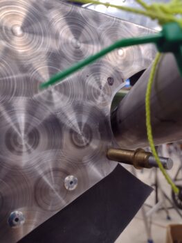
I wanted to get an idea if I would actually need to bend the very aft end of the crankcase vent tube, so I slid it into place… of course checking how the Batman cradles would work out as well.  I’ll need to do a little bit more R&D on the aft bend (I want to be able to get it through the exhaust pipe bracket nub for maintenance without having to bend it back straight).

I then mounted the lower cowling to check out the clearances and how the trimmed exhaust pipes looked in relation to it.

Again, due to the location of the very aft bend on the right side exhaust pipes, and since they are over 1/2″ further outboard than the left side pipes (these right side pipes are as far inboard as they can physically go), to get a decent exhaust angle as inboard as possible (read: pretty much straight aft) I had to trim them farther forward of the cowling trailing edge than on the left side.  Thus, the right outboard exhaust pipe end is about 1.6″ inside the cowling while the inboard pipe is about 1.8″ —centerline of pipe, while the very inboard edge is almost 2″ (pic 1).

I’ll note that on the left side pipes, due to the aft bend, I would have had to trim much further forward to get past the bend to make any real effect on the exhaust.  This would have resulted in the exhaust pipe ends being around 2.5″ to 3″ inside the cowl… just not worth it (pic 2).

And finally, here we have the trimmed exhaust pipes sitting in both the mounted top and bottom cowlings.  Nope, they’re not perfect, symmetrically or stunning in their presentation… but again, I think they’ll work functionally without burning up the cowlings or the prop. Certainly not bad considering the starting point on these cowlings and pipes.

Pushing forward!

Chapter 22/23 – Making Batman merch?!

Yeah, yeah, yeah… I had a whole list of things I was going to get done today, but for an entire litany of domestic reasons I didn’t get close to getting any of them knocked out… theme of this year! (sigh)

I did test out version #3 of the crankcase vent tube to single exhaust pipe cradle.  This version would work more than fine, albeit I may add just some minor tweaks before machining it (still pondering that setup on the mill).

I also tried out making some Batman merch on my 3D printer… ha!  This is what I’m calling a saddle vs the cradle above, but probably should switch those nomenclatures.  Whatever…

This little Batman looking thing is for the aft and forward crankcase vent tube attachments to the right side pair of exhaust pipes.  Again, as to avoid having my aluminum crankcase vent tube crushed, flattened or deformed over the ensuing years of flight.

Here we have the initial test fit on the aft side of the exhaust pipes.  Since there is just a hair of a gap between the pipes I’ll need to slightly tweak this saddle/cradle for a more solid fit.

This shows how the crankcase vent tube will sit inside the new double-pipe Batman cradle insert.

And here is where I plan on securing the crankcase vent tube to the right side exhaust pipes on the forward side.  The single pipe attach point will be just beyond the very upper right corner of this pic.

I also did a fairly thorough assessment of my firewall engine ground situation since my current inside-hell hole grounding point has my engine ground strap trying to displace my fuel pump-to-fuel injection servo hose… not good to have the ground strap trying to gnaw through the primary fuel feed line!  Separation and avoidance is probable best here.  Yet another slight change to my original setup that I’ll be working over the next couple of weeks.

Beyond that, I was able to heat up my Pro-Set epoxy in a big pan to get it back into liquid form versus the big glob of goo that was inside the gallon can just prior.

I do plan on getting a bunch more tasks knocked out tomorrow!

Chapter 3/18/23 – Tidbits n’ stuff

While awaiting clearance and a Tee-time from James to weld up the exhaust pipe brackets, I thought I would knock out a couple of artsy-fartsy craft tasks today.

First off was some Origami, as I bent the new 0.020″ thick 301 stainless steel SC-1 canopy safety catch into the plans shape.  My top 90° bend was a little rounded and not perfect, and the resulting corrective actions in the vise still resulted in a not-perfect part, but definitely functional and not entirely heinous.  Done and moving forward!

I plan on shaping and mounting the 5/8″ diameter aluminum crankcase vent tube to the right side exhaust pipes soon, and in assessing how it would get mounted I noted that towards the front side of the engine I would have the crankcase vent tube strapped to the forward (#4) cylinder lone exhaust pipe with a hose clamp.

Now, I’ve noted on a few Long-EZ’s that over time the aluminum crankcase vent tube deforms and flattens inside the stainless steel clamp, pressed up and secured to the harder stainless steel exhaust pipe.  I guess that’s why James Redmon, IIRC, used a stainless steel crankcase vent tube… but that’d be too heavy in my opinion.

To avoid this deformity on an aluminum tube that most certainly now costs a small fortune to replace, I decided to design what will be an aluminum cradle that will both help secure the crankcase vent tube to the exhaust pipe tube, and help keep the aluminum tube from getting flattened over time.  Here it is, 3D printed in its initial R&D “proof of concept.”

I then did a quick ops check on it with a scrap piece of exhaust pipe that I have on hand.

Not too bad, although there are some gaps from the stiffer stainless steel pipe clamp band not conforming all the way to the cradle sides.

So I added some just a hair more meat to the cradle sides to give it some bigger “hips” and tried out version 2.  Again, not bad, but it needs just a hair more curve to it… yep!  So I kicked off version 3 before heading to bed.

Also upcoming in my adventures is a decent amount of plasma cutting for the firewall and the wing root heat shields.  To ensure my design configurations are spot on for both of these, I want to be able to trace out the parts on cardboard on the plasma cutting table with a Sharpie mounted to the torch assembly.

I talked to Marco regarding this, and he had a good, simple idea of essentially zip-tying the Sharpie to the machine torch and pressing forward.  Naah… his idea, while brilliant in its simplicity, does not waste enough time, nor involve CAD or 3D printing… ha!  Actually, the new shroud I made for the machine torch fits very tightly, and taking it on and off would be a pain, so I’m opting for the longer term solution now: a pen holding bracket that will simply replace the magnetic machine torch mount.

After some more assessment I confirmed that it would be way easier to simply remove the torch and its magnetic mount as a unit and replace it with the pen holder mount, which requires unscrewing and screwing in literally two #10 screws (note: the torch mount is magnetic in case the torch crashes into a piece of metal that tips up during the cutting process.  By having the torch and mount pop off under pressure, this ensures both the torch and the metal don’t get majorly damaged).

I modeled up the mount in CAD in 2 different sessions, both less than 30 minutes each… the first for a test print (not shown) before I fired off the ~6.5 hour pen holding bracket mount 3D print job.

And here it is on the build plate.  The white stuff is stick glue, which helps secure the ABS plastic to the build plate (I was lazy during the thin exhaust pipe bracket mockup prints and haven’t cleaned the glue off yet… it’s a process!).  The tree root looking things “growing” on the bracket are supports, which can be old school standard or new school “tree” supports… clearly these are the latter.

I then removed the supports in about a minute to expose the front and back sides of the pen holding bracket mount.

I had annotated some design tweaks that I needed to do on my actual pen holder (gray thing) years ago when I planned on installing it into the actual torch mount, which would have required removing the machine torch off its mount.  Well, last week I updated the CAD model for the pen holder and 3D printed it.  Again, I’ll note that all this plasma cutting focus is in gearing up for cutting the firewall, CS spar and wing root heat shields.

Here’s the Sharpie mounted into the holder.  Also note I only had one cap screw in the house with me to test out the pen holder clamps, but both worked fine.

Now to check fit on the plasma cutting table.  Here’s the first initial swag, with washers super-glued into the depressions on the back side to hold it to the magnets on the secured torch mounting base.

The magnets don’t have a gorilla grip on the pen holder mount as I would like, but I’m sure I can work around that to secure it.  Otherwise, the fit is good and it appears very functional for marking up cardboard test blanks prior to actual cutting expensive metal sheets (example: a 2′ x 4′ sheet of Titanium is now around $250… don’t want to screw that cut up!).

More tomorrow, calling it a night!

Chapter 18/23 – Final bracket fit check

Over the last couple of days I was able to finish the final cleanup and grinding down of the crazy tack welds I had made on the exhaust pipe brackets.

Here we have the left side top and bottom exhaust pipe brackets, with the sleeves trimmed to length, the tack welds ground down and the surface cleaned up.

And here we have the same on the right side.

To get an initial idea of how the crankcase vent tube will transit through the top right exhaust pipe bracket, I slid it into place.

I then mounted the bottom cowling to check clearance.

The left exhaust pipes —which were the only ones cut and rewelded— now have more clearance between them and the lower cowling (pic 1), mainly because they are positioned inboard over 1/2″ more than the right side (pic 2).  Also, the right side pipes sit a hair lower since not only is that more of their natural positioning, but also to ensure spacing, both physical and exhaust-wise, for the centerline top-mounted crankcase vent tube (I don’t need it depositing oil mist on the trailing edge of the top cowling!).

I then mounted the top cowling to get an idea of what we’re looking at… again, my overall goal here being to merely get the exhaust exiting out of the back of cowlings without burning anything up.  Aim low and meet expectations… ha!

And yes, the right exhaust pipes are still long and poking out the aft opening of the cowlings, and the left side pipes still need final trimming as well.

I texted my welding buddy James about finishing up the welds on the exhaust pipe brackets, and while I await his reply I moved onto just a couple of some of the minor tasks I have on my list.  The first being the removal of the old 0.015″ thick 304 stainless steel SC-1 canopy safety catch, to be replaced with the yet to be bent new 0.020″ thick 301 stainless steel SC-1.  Funny how how 0.005″ thickness and different type of stainless steel can make such a difference.

I had to run to Jess’s house to help her move some furniture for her grandmother, and had about 20 minutes before I had to leave.  Not wanting to waste any time (yep, I’ve done way too much of that during this build!!) I quickly cut up a box for cardboard, then traced out and cut the aft sides of the wing root heat shields.

And yes, I specifically stated aft sides since both forward side wing root heat shields will be set further inside the wing roots (outboard) to also be used as gap seals to block airflow through the wing-to-CS spar gap, each side respectively.  These inset forward wing root heat shields/air gap seals also must be configured as such to account for the oil cooler position at the left wing root, and the AP roll servo position on the right side.

With that, I called it a night and headed over to Jess’s to help her out (ok, and for a yummy dinner too!).

Chapter 23 – Tacky welds finished

It took a bit getting back into the swing of things after our mini-vaca down to Florida.  Plus, a bunch more rain had poured down and, once again, a good bit of the shop was flooded…

Just at the point where I need to do some welding with the lower left bracket mounted back on the engine, only sans pipes.

So after working and dialing in the configuration of the lower left bracket pieces, I then left the bracket overnight to do the final welds the next day since the area immediately under the engine was flooded.  I did do a good bit of mopping, but I needed to let it dry out overnight.  I also spent a good bit dealing with a half-downed ceiling insulation panel: a gift from the squirrels as that war wages on.

Today I did some practice welds before tackling the pair of tack welds to recombine the lower left exhaust pipe bracket pieces.  Yep, it’s not currently looking like a beauty queen, but I think after we weld ‘er up and clean ‘er up it’ll turn out pretty darn ok.

I then spent a good hour drilling out the upper mounting screw/bolt holes in the aft baffle wall and underlying reinforcement plates.  I then mounted a K1000-3 platenut in each upper corner to secure the upper left exhaust pipe bracket, as you can see from the outboard side (pic 1) and from the inboard side (pic 2).

With the mounting screws in place, I then did a number of rounds of final trimming on the pipe sleeves before locking them as tightly as possible to the exhaust pipes with clamps (pic 1) and before hot-gluing the upper bracket plate to the upper pipe sleeves.

After the hot glue set up, I removed the upper left exhaust pipe bracket and took it over to my welding table.

I then tack welded the upper left exhaust pipe bracket with no major issues (a minor issue is that on my last weld the hot glue ignited and there was a fairly decent fire blazing over one side of the bracket!).

I spent a good half hour scraping nearly all the hot glue off the bracket before remounting it into place to check its configuration.  The bracket fits really well and, overall, I’m happy with how all the brackets fit —both left and right sides.

Here’s one more shot of the tack-welded upper left exhaust pipe bracket, from the inboard side looking out.

Tomorrow I’ll clean up all the brackets, then clean up (grind) the tack welds and get these suckers ready to take down to James at some point in the near future to have him work his TIG welding kung-fu magic.

Pressing forward!

Chapter 18/23 – Tacky tack welds

Today was the first test of tack welding the exhaust pipe brackets on the bench and not in-situ on the engine.  I secured the position of the respective bracket pieces and configuration with hot glue, hoping that just a tack weld on one side of the bracket wouldn’t melt the glue on the other side… so in theory I should be able to get 2 good tack welds, which is a decent start.

In general my hypothesis was correct, however I did learn something about hot glue in and around the welding process: it appears to act as a heat accelerant if directly involved in the weld.  I had a couple of welds flare up in spectacular fashion when apparently the glue had melted and wicked down to the seemingly clean section that I was welding on.  The result being I do have one small hole on the perimeter that will need to be filled during final welding.

Overall the op was a success, and after the cleanup I remounted the top right exhaust pipe bracket with good results.

Now, on the lower left bracket the “hot glue accelerant” characteristic really reared its ugly head in a few spots.  It’s essentially analogous to going from 0-60 mph in 0.01 seconds when you’re used to 3.8 seconds (just as an example).

As I was welding the outboard sleeve to the vertical bracket plate my weld apparently hit glue towards the top outboard edge and it blew a small hole out.  I left that weld alone and moved onto a “clean” (or so I thought) area near the thinner edge (bottom center), and between it just being narrow and less metal and an unplanned flair up, it literally just near-instantaneously melted the bracket in half!

The result was the inboard sleeve tack welded in place, and the outboard sleeve gooped up a good bit and the bracket plate now in 2 pieces.  I cleaned up the outboard sleeve in prep for another round of welding, as well as the bigger bracket piece with the now welded-in-place inboard sleeve.  I draw a Sharpie line on the back side of the weld line to ensure the pieces don’t slip out of place (and to tell if they do), so I knew the weld line on the outboard sleeve to tack weld it to the remaining half of the half circle (a quarter circle at this point) closer to the overall midpoint of the bracket.

Here we have both inboard and outboard sleeves tack welded to the major portion of the vertical bracket plate, with the very outboard free and untacked corner of the bracket simply held in place by the mounting screw.

Since I needed to do another round of cleanup and prep to weld in that last piece, and it was getting later in the evening and time for some grub, I decided to punt on any more welding for the evening and do some machining.  I’ll re-engage on the welding Monday with a clearer head.

I started out machining the SC-1 canopy safety catch by first probing the part for zero-zero.

It then took me about 5 minutes to machine the SC-1 on my mill, with some action shots here.

And Voila!  A per-plans spec SC-1 canopy safety catch.  The first one I did, which was a bit of a test, was too thin and bent too easily.  This one should work fine.

And here it is all cleaned up, ready for the metal brake!

And with that folks, I’ll bid you adieu for a few days as I take a quick break down to Florida with Jess.

Chapter 23 – Right bracket’s bracket

Today was primarily about getting all the right side exhaust pipe brackets K1000-3 platenuts and the inboard reinforcement plate installed.

This involved removing the exhaust pipes, which was the first task on the list.  After installing the outboard top platenut, I then positioned and secured the inboard reinforcement plate into place before drilling some holes for some securing rivets.

On the inboard side I installed both top and bottom platenuts to secure the right exhaust pipe brackets mounting screws while also installing a few extra rivets to secure the inboard reinforcement plate to the aft baffle wall…

Here is an inside-looking-out shot of that.

I then reinstalled the right exhaust pipes and the lower bracket before setting all the top bracket pieces into place.  After taking a good look at the pipes, I decided not to do any more in-situ bracket welding on the exhaust pipes.  There was no serious damage, but a bit of discoloration due to the heat.  Best to endure some welding process pain to ensure the pipes remain good and undamaged.

Since the crankcase vent tube pass-thru nub is not directly on the exhaust pipes, I went ahead and tack welded that to the vertical bracket plate.  I needed to make a couple attempts at getting the pieces welded (or “blobbed”) together, since again, I think my 1/16″ filler rod is too big for the task and wanting to go globular vs wetting out nicely.  Oh well, I didn’t blow out any metal so I’ll call it good.  Plus, I consider myself to be quite the adept grinder.

Again, since I’m not doing any more tack welding in-situ, I’m going to try my hand at using hot glue to lock in the bracket’s configuration and hopefully get a few good tack welds in before it melts away… we’ll see.

I also did a fair amount of work on the lower left exhaust pipe bracket as well. I needed to trim the lower outboard corner (and will get to the underlying bracket soon as well) due to it being a tad too close to the cowlings when those are installed.

In addition, I needed to remake the inboard sleeve since after dialing in the bottom bracket it came up a little too short on one side.

I also drilled out the inboard screw position after verifying that the bracket positions were good.  I’ll note that this position will not utilize a K1000-3 platenut, but rather an ‘ol school screw & nut since it also goes through/secures the baffle reinforcement strip.

Finally, I prepped the surfaces at the seams for some upcoming welding (hopefully tomorrow).

We are getting a good bit of wind and rain still from being on the sideline of Tropical Storm Debby, but hopefully it won’t affect my build ops.  In addition, I’ll be out of town this weekend on a short fun trip down to Florida with Jess… so clearly no building for a few days.

Chapter 23 – Top right bracket redo

Many of my peeps out there may have heard that we have Tropical Storm Debby crawling up the Eastern coast of the U.S. with high winds and rain.  I honestly haven’t been tracking it much other than if it will affect a quick trip down to Florida this coming weekend that Jess and I are taking.  That being said, we’ve had rain over the last couple of days… and lots of it.  And when there is what is akin to a torrential downpour, more than the ground can naturally absorb, then my shop floods to varying degrees.  Normally just in a small area in front of the air compressor closet, and maybe a bit in front of my epoxy mixing station.

This time however I was met by flooding well up under the airplane.  And although I do have a mop and bucket for smaller isolated flood puddles, this would have taken way too long to deal with… especially since it was still raining! [Also note the insulation panel under the centerline of the plane: knocked down by the squirrels in the ever-ongoing Squirrel Wars of the Salty Shores Shop].

In short: no welding today.

Not that I’m sure that it would matter if I could weld, given that after a few rounds of dialing in Version 3 of the upper right exhaust pipe bracket I assessed that it would need to be modified too much, causing the top corner mounting screw holes to drop down too close to the edge of the underlying aluminum baffle.  I’m really not sure why the top bracket turned so wonky on me (pic 1).  But, instead of pressing a bad position I simply noted the required configuration changes (e.g. fill the “new” gaps around the sleeves), created and tweaked the Version 4 mockup in cardboard first (pic 2), then uploaded that into Fusion 360 CAD.

By this point I’m getting fairly quick at uploading a cardboard mockup into Fusion 360 CAD, then tracing out the part to model it up before I then post process the new CAD part to create a CAM file for the plasma cutting table (FireControl program).  I then set up and plasma cut the now 3rd top right 316 stainless steel bracket (sigh).

I then cleaned up the edge dross off the bracket, drilled the corner mounting holes, and did some dialing in on the bracket for a few rounds.  Clearly this one is fitting much better right out of the gate.

I’ve got another few minor rounds of dialing in before I’m ready to mount the K1000-3 platenuts that will in turn allow mounting both top and bottom right side exhaust pipe brackets; which will require removing the exhaust pipes.  Since the rain was still coming down hard and I couldn’t get under the plane (in any EZ fashion) to remove the pipes with all the standing water underneath it, I simply called it a night and will tackle it again tomorrow.

Pressing forward… or at least trying to!

Chapter 3/23 – Bracket welding begins!

Again, a couple days accounted for in this post.

With a tropical storm possibly in play for us I desperately needed to cut my out of control lawn.  The problem was my lawn mower wouldn’t start, so a day and a half of testing the battery and then charging it overnight was spent, as well as a myriad of other troubleshooting tasks to figure out what the heck was going on.  I was about ready to pull the trigger on a new battery when I worked all the safety switches on the tractor and apparently one of them was stuck open.  Finally success and I got my darn yard mowed… more domestic duties boogering up my plane-building schedule!

After a couple of hours practice back TIG welding, I felt I had enough time under my belt and was just comfortable enough that it was time to stop the playing around and time to get busy welding for real.  That being said, stainless steel can be a real sticky wicket to weld and I knew my limitations, so I proceeded accordingly.  More on that in a bit.

First off was to get my nicer blue welding helmet back online.  Again, a common hack for these mid-range price welding helmets is to crack open the sealed auto-darkening lens unit to gain access to the one or two batteries that need replaced, to then add an external battery compartment allowing for EZ future battery replacement.  I’ll note that this auto-darkening lens is one I bought as a complete assembly to simply replace the original one on this helmet that had dead batteries… yet another method of replacing dead batteries on these things.  This time around, however, I’m armed with a bit more knowledge and experience.

The battery in this lens assembly sits in the upper right corner; here it’s been removed and only the tabs that were originally “welded” to the battery remain.

Using my soldering iron I removed these battery tabs that were soldered to the circuit board and replaced them with the positive and negative leads from the new external battery holder.  I had to make a small notch in the lens assembly case to allow for the wires to exit through the edge of the lens frame.  Also note the knot in the wires for strain relief.

After some minor surgery on the lens frame of the actual helmet to allow room for the external battery wires, I then remounted the auto-darkening lens assembly back into the welding helmet and secured the external battery module to the inside of the helmet with Velcro.  I then did a final ops test: success, and… Voila!

My spiffy blue welding helmet was back online.  Now it was time to put it to good use!

I spent about 30 minutes doing some TIG practice welds to warm up for the welding of the bottom right exhaust pipe bracket and the half-moon sleeves.  The main issue is that with this thin stainless steel, simple higher amp tack welding —sans filler rod— can be a bit risky and result in blowing a hole right through the bracket/sleeve metal.  Worse yet is what is BEHIND that stainless steel, on the back side: my exhaust pipes.  I simply do NOT want to be blowing a hole through the pipes or damaging them.

The trick in all welding is heat control, and especially here as I’m tack welding this bracket in-situ on the engine.  So filler rod was definitely on the to-use list.  That being said, after a good bit of practice I noted an unseemly characteristic of this specific welding rod used for this 316 stainless steel: it prefers to ball up vs simply melt into the base metal.  I thought this might be due to contamination at first, so tried it on an extra clean blank after prepping it via grinding and acetone… same issue.  My guess is that the rod may be a bit too big in diameter for the amount of amps I’m using, but it’s all I have on hand.

This meant adding just a hair more heat to the weld junction, enough to get this finicky welding rod to work, without melting away or blowing a hole through the thin base metal.  All while working on the bottom side of the engine.  And I’m sure it goes without saying that trying to get enough lighting on the task at hand was problematic in its own right.

Above is the raw, uncleaned bottom right bracket tack welded up.  Ok, so not overly beautiful tack welds for sure, but they did hold very well and I only had a little sticking on the inboard side between bracket and actual exhaust pipe.  A thin flat bladed screwdriver provided the persuasion needed to separate the two and no real damage (i.e. “hole”) to the exhaust pipe occurred.

However, this experience is certainly pushing me to explore how to secure or replicate the positioning of each remaining bracket to allow me to tack weld it on the bench vs in-situ on the engine.  Moreover, any flirting with ideas of welding up these brackets myself is out the window… again, with stainless steel needing that razor’s edge heat control, and this being such thin metal starting out, I’m leaving the major welding up of the joints to James, a no-kidding pro at this stuff.

With the bottom right bracket tack welded, I then spent the next hour and a half measuring, cutting and dialing in the 2 top bracket half-moon pipe sleeves.  As can be seen in the pic above, the bracket plate itself needs some minor trimming to be refitted around these specific sleeves.  Moreover, before any final configuration or tach welding is undertaken, I need to install the K1000-3 platenuts in all corners to ensure I get the very good clamping pressure I need between top and bottom brackets.

And that, my friends, will come tomorrow.

Pressing forward.

Chapter 23 – Brackets… still pushing

Today I cleaned up the right side exhaust pipe brackets and got them fit into place around the pipes, with the pipe sleeves in place.

Here we have the right top bracket in place.

And here we have the bottom bracket fit into place with the sleeves.

My next task was to get the right side inboard reinforcement plate made, which will help secure both the inboard top and bottom brackets’ securing screws.  After getting the reinforcement cut out of 1/16″ thick angled 6061 aluminum (pic 1) I then fit it into place (pic 2)… I have it peaking out from the aft baffle plate simply to be visible.  Moreover, I won’t install the inboard reinforcement plate until I’m ready to install the top inboard platenut, since I’ll need to remove the inboard exhaust pipe to do so.

While looking for a file by my lathe, I noted my eye bolt that I’ll use to weigh down the front of the plane any time I need the nose gear extended.  I had marked the eye bolt for trimming since it’s too long, but never got around to doing it.  Well, since I was doing Dremel work anyway I went ahead and knocked that task out.  This will come in handy since I’m nearing the point that I’ll want to remove all the weights that are currently inside the nose of the plane.  For reference, I’ll note that this eye bolt installs into an embedded hardpoint on the aft wall of the opening for the underside nose taxi light.

Back to another reinforcement plate for the the right side exhaust pipe brackets, this one for the top outboard screw/bolt.  This reinforcement plate is also made up of 1/16″ thick 6061 aluminum.

Once the bottom edge was shaped, I then drilled and riveted it into place using Cherry pop rivets.

It was now time to do some welding, but when I went to open up shop bay 3 for some ventilation, I found this 3″ plus length “sentry” standing guard on a giant web in front of the door.  I “persuaded” him to move with an old branch from my burn pile and continued on with my door opening <wink>.

Once I got my welder, welding station and welding accoutrements squared away, I tried my hand at some high-amp tack welding.  The first welds out of the gate were simply scary, and I had to dial down the amperage quite a bit.  Still, the risk of blowing out the thin walled stainless steel was just too high after a good dozen tries, so I decided I needed to use filler metal and just do small “normal” welds with normal power for my tack welds.  Then I’ll turn over my tacked up pieces to my expert buddy James to finalize the welds… at least that’s the plan.

Tomorrow is a busy day with my EAA chapter meeting in the morning and couple other social events, but I do plan on at least getting an hour or two of welding practice in on thin walled material, etc. before tackling the exhaust pipe bracket tack welding.

Moving forward… cautiously!