Chapter 24/25 – Clearing the Queue!

Or trying to anyway!

Again, since this is during the Thanksgiving holiday, this post covers the last couple of days.  I didn’t get a ton done, but I did make a good little dent.

I started off with making yet another threaded insert —ala baggage pod style— for yet another video camera mount.  This one will be on the very top edge of the left winglet, which has the 1″ added internal foam cap that just happens to be the denser PVC foam. I did this when I constructed the winglets simply because I had a piece of foam that size sitting there and decided to use it.  Well, many years later that denser foam should help in adding some oomph to the pair of threaded inserts going into it… or not.  Either way, that’s what’s going on.

I’ll note that like the other pair of threaded inserts I’ve recently installed, the first one is 6061 aluminum, while the one I just made (nearest camera) is 2024 aluminum.

Yet another small victory I attained was drilling out the 12 year old Saran wrap stuffed into the threaded inserts on the inboard leading edge of the right wing.  These are actually for the baggage pods and it was nice that they cleaned up so easily.

To ensure these baggage pod hardpoints were good to go, I threaded a screw into each one.  Ahh, they work as designed!

Starting late in the afternoon today (Thanksgiving) I got busy knocking down the cured epoxy wipes on the left wing, winglet and aileron top (not the rudder… yet).

Yep, I spent over 3 hours with my trusty orbital sander in hand, with 80 grit discs (a few of them!) to knock down and level out the finish on the left wing, winglet and aileron top.  In fact, it took me over an hour just to finish both sides of the winglet.

I’ve got a good bit of running around tomorrow, and the weather is forecasted to start getting much cooler, but I will adjust as necessary and push forward as best possible!

Chapter 25 – My learning curve

A funny thing happened while I was building my Long-EZ, or technically micro-finishing this bird, in that I realized that except for the canard many moons ago, I have not really dealt with LEADING EDGES in my previous micro-finishing endeavors.

Yes, we all know what happens when we assume things, and beyond using the longboard on my leading edges initially, I really didn’t give them a lot of thought after that since they looked straight.  Again, that assumption thing!

Well, out of curiosity I checked my leading edges on my left wing and winglet.  Wow. What I had assumed was straight was far from it.  The wing leading edge looked ok in merely casually looking at it, but with a closer look it had some significant peaks and valleys going on.  The winglet LE wasn’t as bad, but still not as razor straight as I’d want (especially for a “show bird” as my fellow builder <singular!> likes to claim… ha!).

At this point I would like to highlight that unlike most of my current building buddies, I was not able to avail myself (due to scheduling and relocating overseas) the services of Mr. Stephen James in acquiring his Eureka CNC wing cores. That’s right, although I bought my wing cores from Feather Light, they were still cut the good ol fashioned way: with hot wire and templates.  e.g. not perfectly straight CNC edges!

So whipping up some micro/West 410 was in order, which I slathered on the winglet leading edge last night.  This morning I started knocking it down and didn’t stop until I got it down quite a ways.  Obviously with some added filler on the front, it was going to cause a few gaps where it feathered back onto the existing winglet/fill… so a bit more filler was required to transition those gaps.

Thankfully the wing leading edge added micro-fill, after knocking it down, did not require any extra fill.  The wing LE is pretty darn straight now up until the outboard 18″, which has about a 0.08″ dip until the very tip of the wing, due to the added glass for the wingtip.  Now, I plan on adding a LE “disrupting” landing/WigWag light in this area, so I think that will disrupt the slight dip, so I’m not worrying about it.

If you’re wondering about the already epoxy-wiped right wing and winglet, well, yep… I will be reworking those leading edges as well.  The winglet I’ll do in the next few days.  For the wing I decided to do it with the wing off, LE up, as I’m prepping the right wing for final primer and paint (and installing the LE light on that side as well).

Ok, so for any builder reading this pre-wing/winglet finishing, the trick I now know (in retrospect) is to dial in the straightness of the leading edges FIRST, then contour the rest of the airfoil from there.  I probably read this somewhere in my myriad of research, but clearly missed putting it into application.

Another issue I found that I needed to deal with is the forward side of the left wing end, terminating at the front corner wing tip (AKA Nav/strobe light base).  The micro out here is piled up significantly more than on the right wing.  Clearly we pile the micro up when applying it to then give us a straight, smooth surface… but there is a balance.

First, obliteration of the natural shape of the wing is not part of the process, IMO.  And out here this piled up micro was doing just that.  Again, especially compared to the right wing.  Moreover, our Long-EZ wings have a washout, so although the LE is straight, there is an overall downward curve/twist to the wing as it goes outboard.  And I felt that I was affecting this washout with all my “straight” micro piled up.

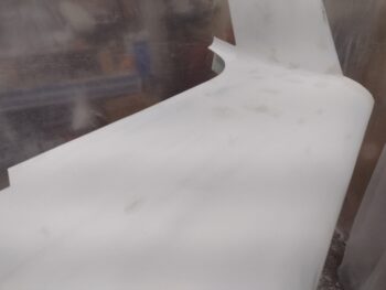
Finally, looking at the wingtip from the outboard end (pic 1) one could see the micro piled up on top to the point that the Nav/strobe was no longer centered on the wingtip, but rather looked low because it was, with more than required micro atop the wing in this area.  Thus, I marked up the forward area of the outboard left wing to knock down the micro a good bit (pic 2).

I have to say I’ve read a number of accounts of builders using long sanding blocks/sticks to ensure the surface is even all the way down the line, and I think there is a good bit of area on the wing that is conducive to this approach. I too of course employed the classic “stick of pain,” long sanding board.  But I also think these wings have some natural (or unnatural really) curves that require the shorter 30″ or 18″ boards to blend in the overall contour in those areas… which is primarily each end of the wing: inboard 2-3′ near the cowling and outboard 2-3′ near the winglet.

All that stated to say this wing end is one of those areas (again, IMO).  My goal here was to knock the surface down approximately 0.1” CAREFULLY to 1) match the right wing, 2) find, ‘allow’ and maintain natural wing washout, 3) have my Nav/strobe light at least somewhat centered on the wing end.

Yes, the micro is still piled a bit higher than I had planned for, right where the wing extension dives into the outboard base of the winglet (pic below).

If looking from the front this matches the inboard height/level of the wing surface intersecting the base of the winglet.  In using a sanding block to knock down this forward area, I of course feathered in the entire area to get a nice transition.  This inboard spot of the wing intersecting the winglet flowed even with the rest of the wing… and to force a reduction in height in such a small area is asking for trouble in my book, given that it could knock out the nice even flow of the entire area and result in a mismatching low spot.

Best to swallow the little frog in regards to my Nav/strobe light position —which is noticeably better— and press forward in getting this bird finished.  [Little frog is a reference to wilderness survival: eat little frogs for protein… easier to gulp down than a big ‘ol frog staring you in the face.  Also pertains to a stock trade going bad: take the little loss (little frog) vs merely hoping as your stock falls off a cliff and losses climb (big frog). But I digress!]

With all my leading edge and wing tip shaping shenanigans under my belt, I started another marathon round of epoxy wipes on the left wing and winglet.

And a mere 6 hours later I was finished, replete with all the protective tape boarders removed and nothing left but to allow the 5 coats of epoxy to cure.

As I did on the right side, I of course also epoxy wiped the left aileron top and both sides of the left rudder.

Another shot of the epoxy wiped left aileron top and rudder (both sides).  Here I only used 4 coats of epoxy before calling these good.

Needless to say, given the time of year and weather situation at hand, I’m very pleased to have the major aircraft components (wings, winglets and strakes) micro-finished and epoxy wiped.  I still need to micro-fill and epoxy wipe the outboard 3′ of the wing bottoms and inboard bottom winglet, as well as the top of the nose, longerons and turtledeck.  And finally, the elevators need to be completed as well.  Thankfully on all those I can focus heaters and heat lamps to keep localized temps elevated to acceptable curing levels.

I expect tomorrow to be a light build day, and the day after is Thanksgiving, so probably even less building then.  Happy Thanksgiving all!

Chapter 24/25 – Pre-epoxy wipe push

Although the majority of my efforts —as felt by my shoulders and back!— were on performing the final sanding and shaping of the left wing, winglet, rudder and aileron, most all of the pics I have are in regards to knocking out the video camera mounts’ threaded inserts install.

Clearly the video camera mount that I am most concerned about is for the left wing, since I want to have both threaded inserts floxed/micro’d in place prior to my epoxy-wiping the wing surface.  That being said, I pressed forward with other video camera mounts since I was currently performing the task on the left wing.  10 minutes cutting glass, doing a small 5-ply layup or prepping a threaded insert/hole for floxing doesn’t add a whole heck of a lot of time in the grand scheme of things.

Here we have the left wing video camera mount with the front threaded insert installed and the aft 6061 insert/hole ready for install (pic 1). Again, I installed the threaded inserts one at a time due to the curvature of the wing and wanting to ensure they were configured/spaced correctly.  I was a step in tow on the right wing, following suit of the left side, with the forward hole and threaded 7075 insert prepped for flox/micro (pic 2).

And an “action” shot of the left side aft threaded insert floxed/micro’d in place (pic 1) while the right side’s front 7075 threaded insert floxed/micro’d in place (pic 2).

I did a number of micro/West 410 refills on the left wing and winglet, with a decent sized one on the aileron as well.  Here’s a representative shot of some West 410 filler on the outboard wing/winglet intersection (just above the Nav/Strobe light position) and some fills on the lower aft winglet.

In hindsight, I guess I could have grabbed some shots of both the rudder and aileron installed, since today is the first time since I micro’d those that they’ve been on the bird. With that, I took a fair amount of time dialing the fit and finish of those in relationship to the wing and winglet, respectively.

Since I had the template I made up for the wing bolt access covers lying about in the shop, I grabbed it, 4 pieces of carbon fiber scraps and some tape (ok, peel ply too!) and in one of the rounds of my epoxy mixing/layups for the video camera mounts, I added this layup to the mix.

As you can see, I simply used the right wing as the “mold” for both the left and right wing bolt access covers.  Here they are after I laid up the 2 plies of CF each side (pic 1) and after they cured, peel ply pulled and trimmed to shape (pic 2).

And a shot of just the right side carbon fiber wing bolt access cover set in place.  These will be painted the same white as the wings (although in my snarkiness I almost want to leave them black to have the appearance that the holes are still open… haha!).  Moreover, I’ll note that I will be making up a pair of these for the wings’ bottom bolt access ports as well.

Back on the camera mounts, here we have the left side after the aft threaded insert installation cured (pic 1), and then a trial fit after I cut the video camera mount to shape and cleaned it up (pic 2).

Over on the right side, with the forward 7075 insert cured, I drilled the aft 3/8″ hole, prepped the hole innards as well as the 6061 threaded insert for embedding.

I then floxed/micro’d the right wing video camera mount aft threaded insert into the wing (pic 1), and then grabbed a shot much later after cure with the mount cut to shape and all cleaned up (pic 2).

BUT WAIT… THERE’S MORE!  I had grabbed a pic of yet another video camera mount on the outboard edge of the right strake, underside of course.  Unfortunately, in my rush to get the layup knocked out, the shot was way blurrier than I realized… so here’s a shot of my placement outline using my 3D printed template (note the drilled 3/16″ holes, as this was after I pulled the layup).

Here we have the right strake outboard video camera mount, trimmed to shape and test “installed” with the screws merely inserted into the drilled holes.  Unlike the wing top camera mounts, this one will be held in place by K1000-3 platenut assemblies that I’ll flox inside the outboard strake once the wing is off.  I’ll note that I will NOT be doing this type of video camera mount on the left side, as my magnetometers are on the outboard left strake and I don’t want any screws, bolts, hardware or video cameras that close to the magnetometers.

Now, I’ll caveat that with I may very well mount a camera on the outboard side of the left baggage pod, somewhere mid-to-aft in location (perhaps pylon).  We’ll see.

For a better idea where the underside outboard video camera mount on the right strake is situated, here’s another shot looking inboard.

Ok, a lot more going on than these pictures tell the tale, but moving forward in prep to get the left wing epoxy wiped —TOMORROW, since the weather is forecasted to cool significantly after that.

Pushing onward!

Chapter 24/25 – Lights, cameras, action!

It’s been quite chilly the last couple of days, so no major composite work in the shop, although I did get some smaller tasks done utilizing heat lamps.  It’s forecasted to be warmer for a couple days coming up, which is when I plan on epoxy wiping the left wing and winglet.

Since it’s cooler in the shop —and given that I want to embed some threaded inserts into the top of the left wing as hard points, pre-epoxy wipes, for mounting a video camera— today (and last night) entailed a lot of lathe work.

Since I’m out of any stock of “baggage pod” threaded inserts from the Cozy Girrrls, I decided to make some myself.  That being said, I should have paid more attention to their dimensions since a while back I ordered some 1/2″ aluminum 7075 and 2024 rods thinking off the cuff that that’s the natural diameter they’d be… uh, a quick check on the Cozy Girrrls’ site and I realized they use 3/8″ diameter stock, vs 1/2″.  And why waste metal and add any weight if not required.  Thus, I punted and did the first batch with some 3/8″ diameter 6061 aluminum I had on hand.

After some knurling, I started by drilling the center hole out (pic 1) to tap the 10-32 threads (pic 2).

Unlike the Cozy Girrrls I added some flox grooves on the side to give the inserts a bit more of hold inside the drilled hole (pic 1).  I then parted off the threaded insert and started the process all over again (pic 2).

Here we have a 3/8″ diameter 6061 aluminum threaded insert, replete with flox grooves in the side.  It’s a little hard to tell, but another improvement I made was that the end that goes into the hole is enclosed, so no more having to tape up that end before installing it.

Another couple shots of the threaded inserts I’m making.  Again, at this point specifically for securing some camera mounts to the outboard wing tops, and also on the top of the left winglet.

First two threaded inserts, hot off the lathe!

I placed an order for some more 3/8″ diameter 7075 and 2024 rods, among a bunch of other bits and pieces, that will come in Monday.  I didn’t want to wait to make some threaded inserts a little more robust than 6061, which is fine (probably for all the inserts in reality) but I wanted one in each pair to be higher strength 7075 or 2024.  I decided on the 7075, which I turned down from 1/2″ diameter to 3/8″… enough for 2 more threaded inserts (pic 1).  I then knurled the surface to provide a textured surface for the flox and micro to grip (pic 2).

And here is the sum total of last night’s and today’s efforts: 5 threaded inserts (3x 6061 and 2x 7075). [Unfortunately the lathe was giving me some grief that I had to contend with, so it took a few hours longer than I had planned… sigh].

After drilling 3/16″ holes on each end, I pulled the cured left wing video camera mounting base off the wing surface.  I prepped a 7075 threaded insert, applied grease to the screw threads, added some clear packing tape to ensure a good release, and drilled the forward hole out to 3/8″.

I added flox towards the top side of the threaded insert, with some flox also into a widened spot right under the wing skin (think washer, or donut) to lock in the insert.  On the bottom half of the hole, since it’s all wing foam in there, I simply used micro to set the threaded insert.  I then inserted an AN3 sized screw into the aft hole to ensure it was aligned correctly (pic 1). I then weighed the forward hole down to ensure the threaded insert was set in place and cured nicely (pic 2).

I’ll note that due to the curvature of the wing, and thus video camera mounting base, I’m installing one threaded insert at a time.

I then determined the position of the right wing video camera mount, which is a little more than an inch further outboard than the left side.  Since the right wing is already epoxy wiped, I put down a piece of yellow adhesive to ensure no errant epoxy gets on the wing.  I then marked the position of the video camera mount and added clear plastic tape over top of the mark.

I then wet out a piece of peel ply first, then 5 plies of glass (BID-UNI-BID-UNI-BID) just as I did on the left side (pic 1) and finalized the layup with peel ply on top (pic 2).

With all my composite work out of the way, I finally got around to the initial sanding of the epoxy wiped strakes to knock down the slathered on epoxy.  As I did on the right wing, I used my orbital sander with 80 grit to carefully knock down the epoxy wiped surface.  I did have a couple break throughs on the left strake, as well as nicking the left wing’s leading edge, so I will be doing some re-filling and re-sanding on those spots.

I plan on wet sanding the strakes with 150 grit tomorrow, as well as continuing to prep the left wing and winglet for epoxy wipes.

Chapter 25 – I’m all wet… sanding

Since I was up until the wee hours of the morning doing the epoxy wipes on both the left and right strakes, I got a late start to my build day.  I also had an early afternoon appointment to get some new tires on my vehicle, so that put even a bigger notch into my afternoon build activities.

Thus, I finally made it out to the shop early evening.  Again, I’m very pleased with how the strakes worked out with the epoxy wipes, especially considering my biggest problem area finishing wise is/was the aft inboard corner of strake, where the wing/strake/top cowl all intersect.  To get this close to ironed out is a big relief and will really be a huge milestone in THIS Long-EZ build.

Specifically here, note the level surface of each strake… looking pretty good in my book.

At some point I was pondering how exactly I am going to cover the wing bolt access ports on the top and bottom of each wing.  I will most likely go ‘ol skool and simply make these covers out of thin aluminum (most likely plasma cut, then painted) or 2 plies of CF… either way they’ll be thin, feather light, and silicone RTV’d into place.

I used some scrap paper to trace the outline of the right wing’s bolt access port, scanned and uploaded that into Fusion 360 CAD and then added 1/4″ extra around the perimeter for a small overlapping lip where it will get RTV’d to the wing.  I put a big hole in the middle simply to save plastic, print time and have an inspection port for my finger if need be.  I then 3D printed the wing bolt access port cover mockup (pic 1) and then test fit it on the right wing’s bolt access port (pic 2).  I think this dog will hunt, and at some point in the near future I’ll make up a batch of these covers.

Now, an issue that I needed to tackle immediately, before I can move forward with micro finishing the right side top cowl interfacing shoulder bump is the rather significant oil canning I have right along this top cowling to fuselage-side shoulder bump.  With the CAMLOC removed at this spot, and thus the natural resting cowl position with no oil canning, I could see at least an 0.08″ gap between top cowl and flange that needed to be filled.

I started with a 3-ply stepped BID layup on the shoulder bump cowl flange side, laid up the glass and then peel plied it (pic 1).  On the inside lip of the top cowl, I also added 3 plies of carbon fiber at the shoulder bump, and peel plied that layup as well.  Also on the top cowl front edge I had a little bit of a break through when I sanded it down level with the turtledeck, so I added a couple of half-moon shaped plies of CF for filler and peel plied that layup as well (pic 2).

Jumping ahead a few hours, here’s the right side top cowl shoulder bump mounting flange with the cured 3 plies of BID.  I razor trimmed the overhanging glass and pulled the peel ply.  Tomorrow I’ll re-drill the CAMLOC hole (which has Saran wrap stuffed into it to protect against any errant epoxy).

Although not a direct build action, a significant task that I needed to tackle tonight was cleaning up the tons of micro dust and piles of micro powder that was currently everywhere within the plastic hanging sheet protective space I made for this micro finishing process.  Although the entire shop does have a thin layer of micro dust on EVERYTHING, it is much less outside the hanging plastic barriers than inside in and around the plane.

Here is the left side area of the plane, where I still need to make some more dust as I will be doing the final sanding of the left winglet and wing-winglet fairing.

I added the shot above really to contrast it with the ~2 hour cleanup I did on the right side —both sweeping and shop-vacuuming— to get the vast majority of that micro dust off the floor, etc.

And the main reason I did the major cleanup on the right side was I needed to commence wet sanding the right wing and winglet with 150 grit sandpaper (again, as per Cory Bird’s method) without turning the micro dust on the floor into micro “concrete.”

I’ll further note that in reviewing my final finishing steps this go around (on the top side of the bird), that I just pulled the trigger on a longer 30″ sanding block and blue wet/dry 150 grit roll of sandpaper just a few days ago, with these delivered just yesterday.

So with new tools in hand, I got to work and wet sanded the right wing and winglet (I still need to do the rudder and aileron top).

I’ll also note while out today, I stopped by my NAPA Auto Parts store —where I bought my Nasson paint— and talked to both the in-house paint guru, and fortunately for me, the Nasson paint rep who just happened to be visiting.  My question was about the dozens of little shiny divots (not pinholes) just below the surface on the right wing that the epoxy had not quite filled in.  When, How and What to fill these was my overarching question at this point in the build.  I also had separate chats with both Mike Toomey and Steve Beert regarding this issue as well.  I have to say these 3 different guys could very likely be in a Barber Shop Quartet, because their respective answers were all in harmony and exactly the same: prime, fill the divots, final prime good before top coat.

So that dear readers is exactly my plan going forward.

It was again very late and I had run out of evening to do all the tasks I had planned to prep the left wing and winglet for epoxy wiping.  Again, I still need to final sand and contour the left winglet and fairing, but I also want to install some hard points for mounting a video camera mounting bracket on the top of the wing (and very top of winglet too, but not as critical for finishing IMO as wing).

In my research on using and mounting video cameras on airplanes, not surprisingly I discovered some companies that make aircraft video camera mounting brackets and components.  I loosely copied a diamond-shaped bracket from one of those companies as the style I would use for my wing-mounted video camera.  I then modeled that up in CAD and 3D printed the template.

The wing video camera mounting brackets will use a pair of 10-32 screws to secure the mount to the wing, much like the baggage pods on the inboard side.  The company that makes this bracket only makes a straight aluminum bracket, whereas I want mine to follow the curvature of the top wing: so composite it is (at least for now).

I first determined where the left wing cable conduit was situated inside the wing, and then positioned the vid cam mounting bracket mockup so that I would have one screw hard point forward of the conduit, and one aft.  I then traced the bracket template onto the wing.

I applied clear packing tape over the traced outline of the template and cut my glass.  The 5-ply layup schedule here is the oft-used BID-UNI-BID-UNI-BID.  I wet out a layer of peel ply first, laid up my glass, and then finished it off with peel ply on top.

Here is a better angle of the positioning of the video camera mounting bracket on the outboard wing (again, sorry for the weird LED-light induced patterns).

Tomorrow I’ll drill the 3/16″ holes in the cured bracket before removing it, then widen the holes in the wing before floxing in the 2 aluminum threaded hardpoints into the wing top (again, ala baggage pods) for this video camera mount… so those threaded inserts can be dialed in before I epoxy wipe the wing.  Then back on the winglet to get it finalized for epoxy wiping.

Pressing forward!

Chapter 25 – The strakes are high!

Today was a twofer.  Two strakes for the price of one!  Yep, I’d buy that for a dollar (Robocop!)

I finalized the right strake top contour by sanding down the added West 410 fill in the inboard aft corner.  As with many things on this build (and assume many other builds… ahem…), it’s not perfect, but it’s pretty darn close.  Unless someone reads this writeup or they have an insanely keen eye, they’ll never know that area contains about a 0.0217″ dip.
Shhhh, I won’t tell if you don’t!

I then got to work on the left strake, repeating virtually the same process as the right strake.  I used my aluminum “yardstick” to mark the low points, sand just those marked areas, rinse and repeat… and I do mean repeat: about 15 times.

Once I got the top contour of both strakes dialed in and the final sandings under my belt, with both a visual and multiple, multiple feel tests (I do at least a half dozen with my eyes closed to focus on the surface), I then exposed all the covered air pockets just as I did on the right wing.  For some reason these guys seemed to be quite a bit bigger on the strakes.  I’m wondering if that has anything to do with these being hollow as compared to the wings… hmmm, I don’t know.  But expose them I did.

There’s a restaurant in the area that has locals’ night every Wednesday that Jess and I have been trying to make it to for over a month now.  Well, I wanted to fill the gaping divots I just exposed in the strakes, so I whipped up some West 410 using the 205 fast hardener in the mix.  I then filled all the air pocket holes and divots before running out for a nice early dinner with Jess.

Upon my return to the shop, I sanded down my pothole fills, then vacuumed and used high pressure air to clean off both strake surfaces before taping up the perimeter in prep for epoxy wipes…

Which I did next.  All 5+ hours worth.

That being said, I’m really pleased with how these strake epoxy wipes came out.

My last task in yet another very late night/wee hours was to remove the protective border tape, to ensure it didn’t get affixed permanently to the bird!

Again, I’m super pleased with how the strakes turned out and the epoxy wipes seem to have good coverage, at least in my initial take.  For now, it’s super late and I’m hitting the rack!

Chapter 25 – Fighting the fight!

So today was a transition day, with a lot of odd jobs and bits getting worked, and of course tons of sanding.

I started off by knocking down the epoxy wiped right wing, winglet, rudder and aileron top very carefully with 80 grit sandpaper.  Just enough to get it smooth and all the shiny areas dulled.  Tomorrow I plan to wet sand it with 150 grit sandpaper and a long board, as Cory Bird describes in his finishing how-to instructions.

I had done some fills on the left side, and one such task was filling in the edges of the left baggage pod’s top wing mounting screw holes, which had chipped a decent bit as I uncovered them.  I used a very thin amount of grease on some spare 10-32 SS screws and used them to keep the flocro out of the holes (pic 1), and as you can see it really worked a treat (pic 2).

I also employed another technique for micro finishing these birds that I found in a Central States Association (CSA) newsletter article.  It’s a rather simple method of finding the high spots on a wing or strake by using an aluminum “yardstick,” or any long piece of straight aluminum, to find the high spots.  You simply slide the edge back and forth on random intervals, using different axes and a pattern shows up where the high points —or ridges— are (pic 1).

I’ll do this a good 6-8 times, then mark up the surface (see below) and sand the entire surface 1-2 times before back to finding the high points.  I will note that after I got the surface as level as possible on the right strake, I still needed to backfill a small patch at the aft inboard area that was a bit too low compared the surrounding surface (pic 2).

I then got busy sanding the top of the left wing to finalize its contour in prep for the next step: epoxy wipes.  I started by marking up the entire top of the left wing using a pencil, the poor man’s guide coat if you will (pic 1).  I then spent a good couple of hours dialing in the surface of the top wing, and I’m happy to report that it is complete and ready for some epoxy wipes… although I still need to finalize the left winglet before that happens.

Tomorrow my goal is to get the right strake epoxy wiped, and finish sanding the left winglet so that the left wing and winglet can be epoxy wiped the following day (the goal anyway).  I need to fit in some sanding on the epoxy wiped surfaces of course too… yes, I’ve had to do some crazy juggling of tasks over the past couple of weeks to get all this micro finishing done before the cold weather comes rolling in… at some point.

But I’m still pressing forward!

Chapter 25 – Popping air bubbles

Today was all about getting some West epoxy wipes down on the right wing and winglet.

But first, I made a fair bit of dust by sanding the right strake top a good bit.  After really getting a good bit of the micro finish knocked down I assessed the surface before applying some filler West 410/micro to the low spots.

Although I didn’t grab any shots, I also did another good round of sanding on the left wing, and am slowly dialing that in… although it still needs a bit of work to get all evened out.  The central wing area is good, but the outer wing and around the wing bolt area inboard are my stubborn problem areas.  The fix at this point is simple and standard in that more sanding should solve my elevation issues.

I also worked over the left winglet again, especially the upper outboard area.  Again, no pics on that.

I then got to work on the right wing and winglet prepping it for epoxy wipes.  At this point I wasn’t going to create any more dust on any other parts until the epoxy is fully cured on the right side (overnight).

To start, I needed to expose all the air pockets that were covered with just a very thin cover of micro.  I don’t want these showing up as blemishes in my finish later on.  I took about 30-45 minutes surveying my wing and winglet surface and simply exposed the air pockets (AKA “popping bubbles”) as I found them.  Here we have a representative before (pic 1) and after (pic 2) of how that looks.

And a whole area of popped micro pockets on my wing.  It’s not really a fun thing to do: making your wing surface look pockmarked and much worse.  But it’s definitely a good thing when all is said and done to expose these air pockets now and fill them with raw epoxy.

I taped off the perimeter of the wing at the leading and trailing edges, and also at the junction with the strake.  I then vacuumed all the surfaces and then went over them with high pressure air to remove any remaining dust.

I cut some 1x2s to create a quick hanging contraption for the right rudder, to allow me to epoxy wipe both sides of it.  I also prepped the right aileron to epoxy wipe just the top surface of that.

Fast forward 5+ hours later we have both sides of the right rudder and the top side of the right aileron epoxy wiped.

Another shot of the epoxy-wiped right rudder and aileron.

And here we have the right wing and winglet epoxy wiped.  Note that all the perimeter tape is pulled.

I’m calling it 4.5 coats since I had some epoxy left in my cup after 4 entire coats and all looked good except for some of the deeper holes and divots, so I simple dabbed a drop onto each one of those.

I only had maybe 6-8 little divot-fill dabs on both sides of the winglet, so I’m simply calling it 4 coats total for the epoxy wipes on the inboard (pic 1) and outboard (pic 2) sides of the winglet.

My epoxy wiping efforts on the right wing, winglet and accoutrements took me well into the wee hours of the mourning.  But, again, after the epoxy cures (as I sleep) I can once again make some dust on the other major components in prep for getting them epoxy wiped as well (whichever one comes out with the best surface contour first!).

Pressing ahead…

Chapter 25 – Sand, sander, sandest

I started off today by sanding down the micro/West 410 added fills to various areas on the left side, the first being the left wingtip, which was a bit “droopy” on the outboard edge.

I also added some micro/West 410 to the left wing’s BL 55.5 dip, where there is an elevation change on the wing.  Some builders sand this to natural contour, while others tend to hide it and have it filled more.  Since I’m very sneaky (ha!) I decided to hide it a bit more and make the top of the wing look a little more even here (pic 1).  Not to waste any leftover micro/West 410, I also filled in a few distinct low spots and any major divots I could find on the wing/winglet surfaces (pic 2).

Again, today with the added fill cured, I sanded all those down a good bit.

I’ll note that when I specify micro and “West 410,” the emphasis for these added fills is on the West 410.  What I’m doing here is essentially cheating by upping the ratio of West 410, which makes the added fill easier to sand without digging into or deforming the previous micro fill.

That being said, I also had enough left over to fill low spots and divots on the left strake as well, which I then sanded smooth today.

As I mentioned in yesterday’s blog post, a goal of mine today was to work all the wing and strake leading edges to get the bottom edge of each smooth/erased, and also the actual shape of the leading edges dialed in to final for the upcoming epoxy wipes.  Well, I’m happy to report that I accomplished this goal… sorry, no pics because it wouldn’t really show any real difference than before.

However, a distinct BEFORE and AFTER difference is the pre-shaping of the left strake leading edge oil heat/fresh air RAM intake scoop (pic 1), and the AFTER shot of that, now ready for epoxy wipes (pic 2).

Jess had the night off so it was date night, and I wanted to get out of the shop mid-evening.  I was working to get the right strake micro completely sanded when I got a call from my local Long-EZ buddy, Guy Williams.  He found a potential problem with his right gear and wanted my help in troubleshooting it.

So after a bit on the phone with Guy, I got back to the right strake sanding.  But alas, I didn’t have enough time to finish it so I’ll have to pick up on it tomorrow.  I’d say currently we’re at about 90% complete on the right strake (that’s not including cowl shoulder or longeron micro), so getting close to epoxy wiping!

In working on the right strake, as I did on the left side, I cleaned up the intersection of the strake where it meets the fuselage side.  Moreover, part of that was also working the right strake root fresh air intake port.  I’ll probably do just a bit more fine-tuning in this area, but it too is very close to final.

Finally, part of my strake sanding shenanigans this evening involved recutting and cleaning up the junction gap between right strake and wing.  I need to add a bit more flocro to both the wing edge and the strake edge where some chunks have broken off, but beyond that, this junction is pretty much final.

Tomorrow I’ll continue to press forward… And hopefully get to some epoxy wiping!

Chapter 25 – Slowly dialing it in…

Last night I added a bit of micro/West 410 to the front and top inboard edge of the right rudder, and today I started off by knocking that down a bit before remounting the rudder. I then spent about 45 min. sanding the front edge of the rudder on both inboard (pic 1) and outboard (pic 2) sides to match the surface level of the winglet at the intersection between the two.  I may need some very minor tweaking after my final checks, but for the most part the right rudder is done.

With the leftover micro/West 410 in the cup from my inboard rudder added fill (and outboard right aileron edge too), I had filled a few key low spots on the wing as well as a bunch of egregious divots.  I spent about 15 minutes with a sanding block knocking all those back to level.

I then dove in on the right aileron, doing pretty much the same with it as I did the right rudder: matching the front and side edges surface level to that of the intersecting wing.

Again, I added some micro/West 410 to the outboard front and side edge, about 8-10″ of the top aileron, and then knocked off the rough stuff before re-installing the aileron.  Besides the outboard area that I added micro to, the remaining front edge of the aileron actually needed sanded down to match the wing surface level, so I taped the edge of the wing and hit the aileron’s front edge first with the orbital sander, then with a straight board (pic 1).  I then sanded down the added micro on the outboard side and leveled that with the surrounding wing surface (pic 2).  Also note the sanded down clickbond install that was also micro filled last night as well.

Here we have the matching surface levels of right aileron to wing, going clockwise from the top left pic, I started inboard near the first hinge and then moved outboard approximately a foot each position.  Not bad…

Although I need to work on the right strake, I chose to focus the rest of my time this evening on the left side since I had gotten the front half of the wing fairly dialed in with a nice smooth contour, but the aft side wasn’t cooperating as much.  The left wing seems to be requiring a bit more attention than the right wing.

After a few rounds of sanding mainly with the air file and 30″ boat board, I made a lot of progress, and tomorrow I’ll start back in with the long board.

I hit the left strake with a couple good rounds of sanding, doing the 45° sanding strokes once to the left, then once towards the right (standard op for all my flight surfaces).

I then spent about 20 minutes just focused on the left strake to wing intersection, mainly at the leading edge.  It still needs some final dialing in, but it’s pretty darn close at this point.

I grabbed these shots for both left (pardon the weird LED light patterns) and right sides.  The right wing is VERY close to being ready for epoxy wipes, while the left wing still needs a bit of work… I’d call it 70% finished at this point.  I also need to work both strakes as well, especially the inboard aft sides of those and their intersections with the top cowling front lip.

I didn’t grab a shot of it, but I whipped a small batch of micro/West 410 and did some filling on the left side, with my main targets being the BL 55.5 dip on the left wing (too low), as well as the wingtip just in front of the winglet leading edge (edge was low compared to wing).  Then, as I did on the right side, I used the remainder in my cup to fill a number of distinctly low spots and divots on both the left wing and strake.

Tomorrow I’ll continue to press forward on both right and left wings, winglets, and strakes.  One specific task I plan on completing on all surfaces is the blending of the bottom leading edge micro with the previous bottom filled surfaces.  I also plan on getting the left winglet squared away, to allow me to install the rudder and get it dialed in.

Pressing forward… slow, but persistent!