Chapter 21/25 – Strake storage hatches

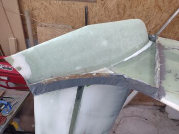
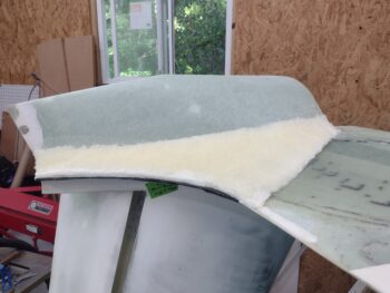
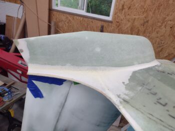
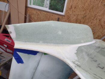
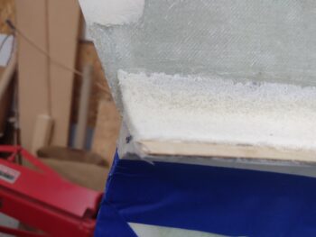
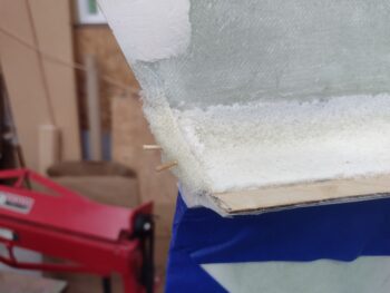
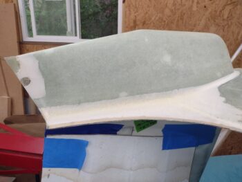
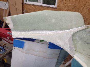
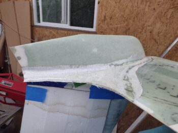
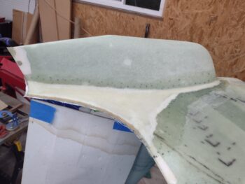
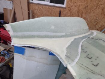
I started out today pulling the peel ply and razor trimming the BID layup on the aft end of right winglet intersection fairing.  Apparently the 2nd time was a charm since all looks good with this layup.

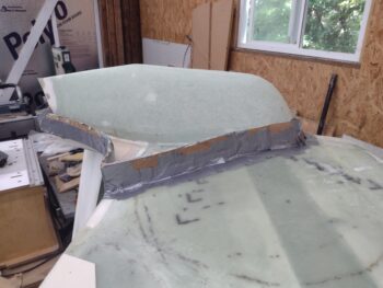
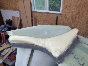
I then did a quick trim of my 3-ply carbon fiber hatch door layup for the right strake storage compartment.  I set it in place to check it’s shape and dimensions.

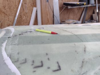
My thought was that with the added material along the outboard edge of the new carbon fiber hatch door I could then simply add a 1/4″ notch to the outboard opening to allow the hinge to more fully open.  So I marked that up just for the hinge area at first (pic 1) and then cut that notch out (pic 2).

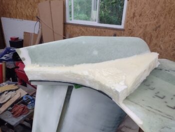
I then cleaned up and refined the edges of my carbon fiber hatch door and set it in place (which I had done in the pic above as well).

Using a scrap of foam I cut to the footprint of the hinge interface plate, and reaching in from the outboard end of the strake, I then marked where the hinge would meet the bottom surface of the door.  I was then able to temporarily mount the door with a clamp to see both how far it would open, and if the door had clearance with the strake top surface.

As you can see below, it had neither.

I then trimmed the outboard edge of the door a bit and got a little bit better opening and clearance BEFORE the door edge hit the top surface of the strake.  Clearly a bit more trimming required.

After another couple rounds of judicious trimming I finally got the clearance that I wanted, with the outboard opening of the hatch now blocking the hinge from opening any farther vs. the outboard edge of the door.

The bad news was that I had to trim off a good amount of door edge to get the clearance that I needed.  This exposed a good bit of that 1/4″ notch that I made. That being said, this was exactly why I was working this entire process to dial all this in (although I guess I could have started with only an 1/8″ notch?? … ha).

After getting a good idea of what I was facing on the right side, I decided to take a break from it and get the left side strake storage compartment hatch cut out.  Using my tiny drill bit method of confirming the perimeter edges, and then confirming my painters tape “map” position detailing where the hidden treasure that is the hatch door . . .

I got the outline marked up on the left strake top (pic 1) and then carefully proceeded to cut out the left strake storage compartment hatch door (pic 2).

Here’s an idea of how the left strake storage compartment will look once installed and operational.

I wanted to compare the two sides by placing the right hatch door onto the left strake hatch opening… and although the shapes are just slightly different due to the front outboard corner (bottom right of pic), they are very close to the same shape and size.

Here’s a wider angle shot of the right strake hatch door open . . .

And the same with the left side.

My last build task of the evening was to micro the 1/4″ notch piece back into place on the outboard edge of the opening on the right strake storage hatch opening.

But before that, I shot a short little video covering my strake storage compartments and doors.  It’s a bit raw and hastily done, but it gives my take on these strake hatches and details in constructing them.

And with that, I called it a night!

Chapter 21/25 – Another task redo

I started off today checking my right strake bottom video camera mount where I floxed 2 platenut assemblies inside the outboard strake.  The cure was good and I removed the tape and remounted the mounting plate.  To reiterate, I used MGS 335 for the flox on this job.  Task complete.

I then checked the aft end of the right winglet intersection fairing where I had laid up a ply of BID using West epoxy and slow (206) hardener.  I looked at this layup as more of finishing layup vs structural, so West should have done fine.  But it didn’t.

I don’t know if it’s the very high humidity that we currently have, but the layup just didn’t cure at all (see end of post).  I also experienced not completely cured West epoxy on the underside right wing epoxy wipes, where it kept gumming up my sandpaper.  I stopped my sanding to reattack tomorrow with another full day of cure under my belt.

Ok, not related to the West issue, but not wanting to waste any epoxy I did use some of the MGS 335 flox from the right strake video camera mount platenut attach, mixed with some micro to cut it a little, to then fill the corner on the left side aft nose/avionics cover; where it mates with the corner of the canopy.

Over on the left wing, I marked the extended bottom flange for trimming (pic 1) to give it 1/8″ more to the flange to cover the gap caused by adding a thick washer at the wing bolts.

I then used my Fein saw to trim the added glass and micro before sanding it down smooth (pic 2).

I want to get as much glasswork and layups out of the way as possible on this build, and knew that I had a few more to do on each outboard strake storage compartment… one of the few big sub-projects left on this bird.

I grabbed my painters tape “map” diagram for the right strake that outlines where I need cut to get the storage hatch open.  I of course just needed to verify that it itself was in the correct location and orientation… note the very small diameter drill poking up from the aft inboard corner.

Once I nailed down the map’s “coordinates” I was cleared hot to start cutting out the right strake storage hatch door.

Here is the inside view of above, with the blade peeking through right at the front face of the CS spar (left top of pic).

It took a little bit to get the curved corners cut out since I couldn’t use the Fein saw there, but after drilling a line of small holes with the tiny drill bit, I then used my razor knife to cut the corner glass (pic 1).

I then set the hatch door back in place to check it’s fit (pic 2).

And removed the tape to get a general idea of how it will look once the install is complete.

And another shot looking straight aft from the front.

And a look at the storage compartment from inside with the hatch door off.

You may remember I mounted and then buried a spring loaded hinge —the same used for my cowling oil check door— which I then wired into the closed/down position as I floxed the top strake skin in place (pic 1).

I quickly discovered that by following my cutting diagram on the blue painters tape, that I hadn’t allowed for the thickness of the top strake skin, which is just under 0.5″.  The thickness of the top skin is blocking the hinge from fully opening (pic 2).

Moreover, after testing the hatch door in place on the hinge, I realized it would not have the hinge-side edge clearance to allow it to freely open or close.

Although not 100% on my plan going forward, I wanted to get a thinner hatch door “in the oven” and started.  I made a cardboard template of the original hatch door, and then added about 3/8″ on the hinge side when I cut out 3 plies of carbon fiber.

I set the original hatch door back into the strake cutout and taped it over with painters tape and clear packing tape.

I wet out peel ply first on the tape, then wet out the 3 plies of carbon fiber (pic 1).  I then finished the carbon fiber layup with peel ply (pic 2).  This got an alternate, correctly contoured hatch door curing overnight that I can use tomorrow in my figuring out this issue.

Back to my West epoxy failure for my initial right winglet intersection fairing aft face layup.  Below you can see the uncured and pliable BID that I ripped off.  In addition,  over 8 hours from this morning the micro was still rubbery and easily broken in parts as shown here.

For the carbon fiber layup I did above I used Pro-Set epoxy, and with some left over in the cup I mixed up some micro, applied it to the foam and inside edges (pic 1).  I then laid up a ply of BID and peel plied it (pic 2).

Hopefully this one will take!

I’ll continue to charge forward on this build tomorrow.

Chapter 25 – Layups getting rarer…

on this build! (smile)

But first, a vital point: NEVER SAY ANY DEFINITIVE LAST WORDS.  Lest they pop up and bite you in the hind end.

Thus is the case after my big claim that the last large area of micro and epoxy wipes were a thing of the past on this build after I glassed the bottom winglet intersection fairings and micro’d them with the outboard underside of each wing.  Then when checking the right underside wing-to-aileron elevation I discovered the trailing edge of the wing, just forward of the bottom aileron forward edge, was way too high.

Over the ensuing days post this discovery, I spent over an hour each day sanding down the area forward of the aileron, which kept having to be feathered farther forward the lower I got at the trailing edge, which was essentially the original wing’s glass surface. I then micro’d up the entire area to get all the irregular lumps and elevations back smooth again.

Well, this morning I spent nearly 2 hours sanding the micro on both the bottom wing and aileron.

With the underside wing contoured and smooth, as well as the aileron, we’re back to having acceptably level and very closely matching elevations across the aft wing surface to the bottom surface of the aileron.

Next it was time to get the gap sorted out and with plans spec, which is 0.08″ min to 0.2″ max gap along the underside interface between aft wing edge and the front lower lip of the aileron (the rounded full length weight bar).  My taped popsicle stick is a little under 1/8″ thick, which with paint should put my gap at around 0.1″ +/- 0.015″.

To get the gap correct, unlike on the left side, this time I used the Dremel tool with a cutoff disk and over a half-dozen iterations to get the wing edge trimmed down to get the correct gap.  Then a few rounds of sanding and Voila!  Wing-to-aileron gap within plans specs.

With both the right wing-to-aileron elevation and gap looking good, I then epoxy wiped both the underside wing aft center area and the bottom of the right aileron with 4 total coats of raw West epoxy, with 206 slow hardener (I normally use 205 fast).

I then worked on my last official foam-covering layup on the aft end of the right winglet intersection fairing.  I first cleaned up the glass edges and then cut/sanded/cleaned the foam edges to create “flox” corners, but for weight I’ll be using micro (pic 1).

Since this is not a high stress area I simply used West epoxy to whip up some micro and apply it in the edge troughs and on the surface of the foam, both top and bottom (pic 2).

I then laid up a single ply of BID (pic 1) and then peel plied it (pic 2).

Although not critical for getting this bird in the air, but since I have access inside the outboard right strake with the wing off, I decided to go ahead and make up 2 each K1000-3 platenut assemblies to secure the right strake’s outboard underside video camera mount.

Here are the 2 K1000-3 platenut assemblies that I just assembled (pic 1), and then floxed (MGS 335) into the inside of the outboard right strake —after sanding the attach spots and hitting them with Acetone (pic 2).

And here we have the external side of the right bottom strake for the floxing in place of the K1000-3 platenut assemblies: bolts with grease applied, taped up camera mount base, with taped up wide area washers.

I then left my layup and floxing to cure overnight as I called it a night.

Chapter 25 – Mash them brakes!

I spent most of the day today from early morning to early evening at Guy’s hangar in our attempt to get his left brake line filled with brake fluid.  The first system we tried yesterday, from Aircraft Spruce, was a gravity system that just did not work whether the nose was up or down.  No Joy.

The next system that Guy bought locally was a vacuum system, which while it did get more brake fluid into the system, it still didn’t fill the lines.  We fiddled with that for a good couple hours this morning trying to make it work, before again calling No Joy on that one as well.

Luckily, I got some good actionable intel from my buddy Dave Berenholtz back in 2022, after which I bought a pressurized brake fill/bleed unit off Amazon… which I brought with me to Guy’s hangar, having never opened it previously.  So after a couple false but promising starts with my brake bleeder, we went to Lowe’s to pick up some fittings and an on/off valve.

My upgrade mods to my pressure system worked a treat and after days of failed attempts to fill this damn brake line (including ensuring the lines were not obstructed) the new setup filled the entire line very quickly: in less than a minute (@ ~17 psi).

Now, while investigating and researching brake bleeding issues and techniques on the COBA forum, I ran across some more good intel regarding brake line runs from wheel caliper to master cylinder, from Marc Zeitlin and a couple of others.  The one big rule of thumb I took away from these discussions was DO NOT have any major loops, peaks or even valleys if you can avoid them.

Not being a “brakes guy,” I didn’t realize the configuration of the brake lines was so critical since I figured it was all just internal pressure anyway.  But the main critical issue is to always be able to bleed the brake lines well and remove any air bubbles, which any loops or high points makes a lot more difficult, and provides a big potential point where air bubbles can get trapped.

I didn’t follow these guidelines (that I never saw previously) when I made “service loops” in my brake line runs in the hell hole.  I ran about a 6″ high loop up the aft side of the GIB seat just in case I ever needed to reconfigure or have extra aluminum brake line to work with.  I’ll get in there and remedy this before first flight.

Another issue noted by Marc Z. was to NOT use the 1/4″ tubing that is standard on Matco master cylinders, but rather smaller diameter 3/16″ or 1/8″ tubing, the latter being preferable.  Why Matco goes with a larger tubing as standard is something I’ll have to investigate.  But Marc’s claim was backed up by a number of other online non-canard posts, with a few pointing to using 1/8″ tubing from brake caliper to master cylinder, and then 3/16″ tubing from master cylinder to the clear external reservoir.  This is what I am going with as my new configuration, so I pulled the trigger on new fittings from Aircraft Spruce.

In related news, Guy is a couple inches taller than me, and when he climbed into his bird to manipulate the brake pedals in the normal sitting position, I took note of where his feet were located inside the nose.  I grabbed a shot of his internal nose (short style) configuration as a guide to when I do my final pedal installs/rudder cable rigging.

The bottom line is that although I spent a good bit of precious time helping Guy on his brake issues, I learned some critical lessons regarding my brake system, including how to use my pressurized brake filler/bleeder unit… replete with spiffy new mods.

Back in my shop, being a bit worn out from the day’s shenanigans in yet another crazy hot workspace (Guy’s hangar), I wanted to get at least the bottom right wing micro’d up… which I did, including the bottom of the right aileron as well.

And with that, I called it a night.

Chapter 25 – Cause and effect…

Another 100° shop day…

I note the heat because it really does have an effect on the build: between being drenched head to toe in sweat (light green on bottom of shirt is the actual color!) and trying not to have sweat pouring off of you into layups, micro fills, etc.  Not to mention just the toll it takes in energy to get this stuff done.

On the underside right wing, along the edge just forward of the aileron, I finally got the offending boat paint primer and micro fill knocked down to get the wing surface level with the bottom aileron surface across their intersecting gap.

This is yet again another multi-day post here, and it’s taken 3-4 good sanding sessions to get the wing surface knocked down to an allowable surface depth to get to a decent “level” ruler across the joint.  I’ll note to get the final sanding task done I resorted to using my belt sander to very carefully remove the very hard primer and micro.


Back in my shop I’ve gotten back to work on the aft nose/avionics cover front and aft edges to the nose (front) and canopy skirt (aft).  Here you can see some pencil lines on the front edge of the cover to be sanded down off the bird to get it close to the level it needs to be for a nice smooth transition across the seam.  Once I’m very close, then I’ll simply hand sand across the seam.

Here we have the aft nose/avionics cover aft lip that interfaces with the front edge of the canopy skirt.  This aft lip is also marked with pencil lines for sanding (round 2).

Here we have the left canopy to longeron seam.  It doesn’t show up on camera that well, but I need to do more work and add some micro to this left canopy frame-to-longeron seam since the gap is just too large…

And this is after spending a good 45 minutes each side sanding the rounded corner edges of the Turtledeck and aft longeron to get the canopy to seat correctly back in place and lock fully with the canopy latch.  Note the top of the Turtledeck is just a hair proud, and this area too I’ll be sanding across the seams (the canopy frame needs repainted anyway).

Getting ready for the upcoming soon primer and paint, I’ve been taking care of all the myriad of blemishes around the bird.  Here I’ve filled a slight dip on the edge of the left winglet fairing “TE” with micro, then sanded it down after cure.  I epoxy wiped it with a couple of coats to ensure no pin holes.

A couple of years ago I spent a good bit of time measuring my entire bird to get it as straight, balanced and symmetrical as possible between left and right wings, et al.  This meant adding another thick washer for a total of two each to the outboard wing bolts on the left wing. This made the bottom wing gap with the strake significantly wider than it was prior: >1/8″ versus the previous <1/16″.

To extend the bottom wing flange edge forward at this junction, I laid up a ply of BID across the pre-existing flange and let it cure with some overhang.  I’ll add 0.1″ of flocro to the front of the bottom lip to fill in this widened gap resulting from the extra wing bolt washers.

I also should have paid a little bit more attention when epoxy wiping the bottom surface of the left aileron.  Once again, being in a rush cost me in the end.  I had a few significant drips that ran down onto the face of the already sanded-for-paint topside surface.  In the resulting removal of these offending epoxy drips, I cut through the surface on the top edge for a couple inches and also on the front face of the aileron, both requiring subsequent micro fills (sigh!).

I filled about a 1/4″ high by 3″ long strip on the right sidewall just below where the canard exits out of the nose.  Although not in a very noticeable spot, I just wanted to get this depression even with the rest of the surface of the sidewall… so a quick micro add, then sanding.  Here it’s been epoxy wiped a couple coats.

Back to the aft nose/avionics cover… here we have it after the 3rd round of edge sanding, with some areas both on the cover and adjacent to it on the fuselage that needed some added micro.  There are a few more required touchup areas that I’ll get to, I just wanted these cleared out of the queue first.

A final look at the aft nose/avionics cover intersection seam with the forward nose.  Looking pretty good, with a few minor tweaks left.

I will note that the final cover configuration won’t be complete until I get the no-kidding final surface of the canard dialed in to as near-perfect as possible, since it is a very critical —if not THE critical— flying surface on this bird.

Tomorrow I plan on slathering up the underside right wing with micro, as well as a good swath down the center of the bottom right aileron as well. Once those are sanded, then a final epoxy wipe and ti will be close to ready for paint for the right wing.

Yep, still pressing forward!

Chapter 25 – Final big epoxy wipe!

Yet another significant milestone knocked out today: the final major epoxy wiping of the last large surface on this bird.  I’ll note in this pic below that the shop lights are off in 2 of the 3 bays to keep the bugs from playing Kamikaze and sacrificing themselves for the “greater good” . . . in my epoxy!

Yep, today I quickly sanded all the micro touchups that I added yesterday, and then got to work laying down 4 coats of epoxy wipes.

One last shot of the epoxy wiped bottom outboard right wing, inside bottom winglet, and the winglet intersection fairing.  I pulled the wing outside to keep the dust down in the shop as I sand a bunch of the boat paint primer off the bottom of the wing (below).

Here is the classic BEFORE pic on the left, and the AFTER pic over an hour later on the right.  I need to load up some fresh sandpaper since by the time I got to the narrow end of the wing I felt as if I was merely polishing the wing vs removing the primer.  You can see I’m also really fine-tuning the surface contour of the bottom of wing as well with all this sanding.

Finally, the strip of paint removed from just forward of the aileron is due to a distinct elevation mismatch between the bottom aileron surface and the wing, with the wing lower than the aileron.  My remedy, at least the initial effort, is to remove as much material as I can to get these surface levels as close as possible.  If need be I’ll add a scooch of micro onto the aileron, but that will be my last option to avoid adding weight if possible.

When I epoxy wiped the bottom of the left aileron, I also epoxy wiped a good bit of the outboard left rudder on the side closest to the hinges.  I removed the left aileron to hopefully sand down the epoxy wipe tomorrow, and also removed the left rudder. I then wet sanded the epoxy wipes on the outboard left rudder.  I also did some final clean up sanding around the rudder cutout on the winglet.

In prep for finalizing the the no-kidding final fit and configuration of the aft nose/avionics cover in relationship with the forward nose and front canopy skirt seam I ordered some winged CAMLOC studs to use on the 4 securing hardpoints inside the nose (2x -12s and 1x -11).  The 4th CAMLOC stud is a -13, which nobody (Aircraft Spruce, Wicks, SkyBolt) has in stock.  Actually, they didn’t have any of these in stock and I bought the -11 and -12s off of eBay.  I’ll keep looking for the apparently ever-elusive winged -13 stud.

Have you ever wondered what that slot is in the top jaw of your CAMLOC pliers?  Yeah, I never really noticed it either.  But now I realize it sure comes in handy when installing a winged stud into its grommet (pic 1).  So here is my new 75% wing CAMLOC stud lineup for the forward positions inside the nose that secure the front edge of the aft nose/avionics cover (pic 2).

And here they are installed.  They work a treat since I don’t have to try to get a screwdriver up in there to pop them opened or closed… I can do it all by feel now (except for the #4 position… for now).

My installing and ops check of my new winged CAMLOC studs was part of my final fit and finish of the aft nose/avionics cover in its final integration with the forward nose surface and the front edge of the canopy skirt.  And yes, the very final fitting task will be when I finalize the canard surface in fine detail and integrate it with this cover as well.  Although I did do a bit of sanding, tonight was more of a recon and getting my task plan created.

I expect a few days of sanding, micro filling and epoxy wiping left to do to accomplish this integration, but when done the aft nose/avionics cover will be ready for primer and paint.  It’s also the last task I need to do before sanding down the canopy frame paint and repainting it as well.

Pushing towards paint!

Chapter 25 – Final big micro sanding!

Today was all about the last big area micro-finish sanding that I plan on doing on this bird (ok, perhaps some might be required on the baggage pods).

I started by pulling the inverted right wing outside on its dolly (which meant half hour of getting my big power tools moved out of the way and stowed), before spending a good hour hitting the cured micro first with my air file, then with the Jitterbug sander.

Here’s another shot of the initial power sanding of the micro on the right wing lower outboard wing, inside winglet and newly glassed bottom winglet intersection fairing.

I then spent about 45 minutes hand sanding the newly applied right wing micro, first with the 30″ long board, then with some smaller sanding blocks.

No micro —that I’ve done at least— is ever immediately ready for epoxy wiping right after its initial sand down to shape, and this was no exception.  I whipped up some micro, heavy on the West 410 and filled all the bigger holes, scratches and major divots in the micro finish.

I then used some of the micro left over in the cup to apply a layer on the just-glassed aft end of the left wing’s winglet intersection fairing.

Jess had the night off, so before heading off mid-evening for a relaxing date night, I wet sanded the epoxy-wiped right side fuselage.  It was nice and smooth after the sanding… ready for primer.

Still pressing onward!

Chapter 25 – Last major micro-finish!

Yes, I’m continuing to highlight just how friggin’ hot it is inside the shop… yet another 100° shop day.

I started off by pulling the peel ply from the right winglet intersection fairing.  All looked good and after some minor cleanup and sanding, it was ready for micro.

Which I got to next… here is the last major segment of the plane that required micro, yet another major milestone (#3 major milestone coming up with the last major epoxy wipe!).

I then did a good bit of sanding and then wet sanding on various epoxy wiped areas: aft wheel pants and turtle-deck, as well as some errant epoxy on the topside of the left wing TE and winglet fairing.

I also knocked out some non-planned tasks inside the inverted right wing root, adding some more heat shield on what is actually the top inside surface of the wing root, and adding a ply of BID to each forward face of the 90° heat shield mounting tabs, as well as some micro fill and a ply of BID over the modified angled corner where the front inside wing edge meets the CS spar flange (both for cosmetic and reinforcement reasons).

I also cut out the edges of the foam on both top and bottom segments of the aft face of the left winglet intersection fairing.  I essentially made “flox” corners for laying up a single ply of BID, but for weight reasons I used micro vs flox since this is not a critical structural component.

After laying up the BID, I then peel plied the layup.

With that, I called it a night and left the layups and micro’d bottom right outboard wing and winglet areas to cure overnight.

Chapter 19/20 – Last major layup!

Today I did the last major structural layup on this Long-EZ build.  To be sure there are still a myriad of small layups such as the tabs on the vortilons and the aft faces of the winglet intersection fairings, but as far as no-kidding bigger, must-do structural layups for this bird to fly, this right winglet intersection fairing is the last one.

Again, here is what the bottom of the right wing and winglet looked like this morning when I started… with a couple small caveats.

Those caveats being the bottom winglet aft corner reinforcement layup and the light washer embedding for securing a protective corner cap via magnet.

I then got to work reusing the same tape covered cardboard strips to make up my pour foam dam around the winglet-to-wing intersection.

As before, I dumped enough pour foam mixture in the dam to create a lot of foam, about 90% of which would be removed.  But I wanted to ensure that I didn’t have to redo any pour foaming, and thus the large amount of foam (pic 1).  I then trimmed a good bit of the foam off before removing the dam (pic 2).

And spent nearly an hour trimming and sanding the pour foam down to its final shape.

I had a small oops in that my aft dam piece must have slid forward when I taped it, leaving an area uncovered by pour foam.

To remedy that I simply used a chunk of cured pour foam, did a rough shape to fit into place, and then used fast hardener to mix up some micro to glue the foam filler extension piece into place.

While the micro’d in place aft filler foam piece cured, I then got busy cutting a ply of UNI, a ply of BID and a piece of peel ply for the layup.  I also gave the surrounding glass a good sanding and cleaning.  By the time that was all done, the micro had nearly completely cured and I trimmed and sanded down the foam filler extension piece in prep for the upcoming layup.

I then whipped up some Pro-Set epoxy and some wet micro to apply to the foam.  I used some thicker micro around the edges and a few big pockmarked areas in the foam (pic 1).  I then laid up the ply of UNI and wet it out (pic 2).

Next came the ply of BID, which I carefully laid into place (pic 1) and then wet it out as well (pic 2).

And of course let’s not forget the peel ply!

By this point in the evening it was starting to get late, especially after doing a good round of cleanup from both the foam sanding and the layup.

But I wanted to knock out one more task, which was to expose the threaded insert in the bottom wing surface that serves as a wing tiedown hardpoint.  The location is just off the tip of the red pen in the pic below.

Here we have a closer view of the embedded (back in 2012!) threaded aluminum insert that will serve as the right wing’s tie-down hardpoint (pic 1).

I then carefully drilled out the covering glassed wing skin to reveal the 10-32 threads of the aluminum threaded insert/hardpoint (pic 2).

One quick check of the threaded insert “functioning” by installing a 10-32 bolt, and all is good here.  I love it when a 13 year old task is completed! (I then filled the threaded insert with plastic Saran wrap in prep for micro-finishing this area of the wing).

Tomorrow I’ll clean up this layup and then micro up the bottom of the right outboard wing, inside winglet and just-glassed winglet intersection fairing.

Pressing forward!

Chapter 25 – More musical chairs…

First off, as a point of note: the heat wave continues… mid-90’s in the shop later in the evening.  Yes, the heat is a factor that I’m currently dealing with on this build.

Another multi-day blog post here.

I took this later in the evening after I knocked out some final wet sanding on the areas of the bottom wing.  I spent the first half of the day out at Guy’s hangar helping him get his main gear up to snuff.

And here is the bottom of the left aileron, epoxy wiped and left for curing.

Here is some of the work we’re doing on Guy’s Long-EZ, currently on the right gear.  It may be hard to tell, but I repainted pretty much the entire right gear leg yesterday, and today we’re mounting the right axle with the new 1/4″ spacer and 1/16″ thick larger area heat shield.

We discovered that the AN4-25A bolts that Guy had ordered from ACS were too short, plus we didn’t have the right nuts on hand.  I had AN4-26A bolts and the correct nuts at my shop, so we scheduled another round of work to knock this thing out the following day.

Still, here are some pics of the new spacer installed along with the new heat shield.

As yet another side “project,” we discovered that one of Guy’s hangar mates got careless moving around a Grumman Tiger and dinged the nose of Guy’s Long-EZ (sorry, no BEFORE pic as it was HOT and I was working mainly on the gear).

I cleaned up the Quarter sized ding where it chipped the paint off as well as left 2 decent sized scratches across the nose.  We went to a local auto parts store to get some filler, but they only had bigger cans of Bondo or a JB Weld filler, which we tried.  You can see the repair a bit still in the middle of the right hand light reflection.  Another issue was the paint match wasn’t the best, leaving a slightly greenish tint after I painted the nose, so there is a distinction (plus, I don’t claim paint blending as one of my skills!).

That all being said, it does look better than with the big ding and scratches on there, but definitely not better than the original un-damaged nose.

The evening on day 2 after working at Guy’s hangar… he came over to my shop later in the evening to help move the left wing onto saw horses, flipping it back upright in the process.

He also helped me remove the right wing on the wing removal/installation dolly, and then transfer the wing to the wing dolly that the left wing had just previously been on… the right wing of course inverted at this point.

With the left wing back upright, I took the opportunity with first the Fein saw and then a hand sanding block to trim/clean up the top strake-intersection flange on the front face of the wing spar.  Pic 1 shows the before, where I had added in some micro in spots to clean up the lip, and the after pic when it was trimmed, sanded and cleaned up (pic 2).

Although it was getting late, I cut 4 plies of BID off the roll to create the two 2-ply corner BID tapes for topside flanges for both the right wing and strake.  Since it was late I only laid up the glass on the aft top edge of the right strake.  Here we have the 2 plies of BID prepregged and ready for epoxy.

And here is the layup, after peel ply, of the 2-ply corner BID tape that connects the aft top flange underside surface to the aft face of the CS spar, right side of course.

Here we have a shot of the underside surface of the right wing, including the unfinished bottom side of the right winglet intersection fairing.

I noted that although not chipped, the aft bottom corner of my right winglet was quite rounded, so I added the same postage-stamp-sized combo of UNI + BID onto this corner, with peel ply.

I also quickly dug out the TE micro and floxed in an AN-3 sized light washer for securing via magnet my eventual corner cap, which should keep the aft corner from getting damaged and/or puncturing any potential victims.

It’s definitely been a very busy past few days, for both my and Guy’s Long-EZs, respectively.  It was very late, still very hot and so I called it a night.