Chapter 13/22 – Sidewall glass done

Greetings from Charleston, South Carolina!

Jess and are down here to roll in the New Year, and we hope you all are doing well!

This blog post again covers the past 2 days.

I first started off by measuring out my center 2.5″ internal conical depression in the sidewall and from that edge forward filled the cut sidewall rudder cable conduit channel with PVC foam, micro’d and pressed firmly into place.

I worked on some wire labeling and confirming the operation and control wiring of a couple of relays, which all checked out good.  I also did the final install of the battery bus (pics to follow soon).  In the few hours it took to do all that, the micro securing the foam in the sidewall channels pretty much cured… at which time I trimmed the excess foam, before wetting out and laying up 2 plies of BID over the foam and the sidewall edges of the channel that I had sanded and cleaned with Acetone.  After the layups were in place, I then peel plied them.

I then left these layups to cure overnight.

This morning I pulled the peel ply and cleaned up the edges of the layups.  I then marked the shallow diagonal lines from the wider embedded G10 washer narrowing going forward to the just glassed forward channel.

After cutting the top and bottom diagonal edges of the middle internal conical sections of the rudder cable spring channels, I then sanded and shaped the foam.  I also made “flox” channels on top and bottom edges of the foam and sidewall glass, where I filled them in with flocro.  For the channel internal foam I used micro before laying up 2 plies into the channel.  I of course ended the layups with peel ply.

I then left these layups to cure as Jess and I scurried off down here to Charleston, SC… again, to roll in the New Year!

Cheers to you all!  Happy New Year!

(And?!  STILL pressing forward!)

Chapter 13/22 – Nose wired up

This post covers the past 3 days, where I didn’t get a whole lot done.  Christmas day I didn’t do anything, and half the day after I lounged around and took it easy with my wife.

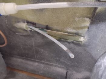
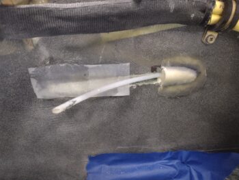
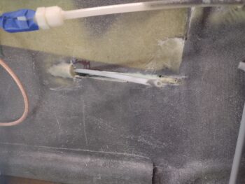
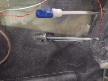
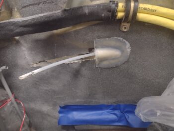
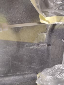
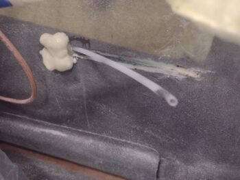
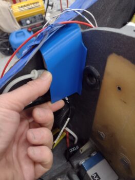
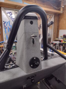
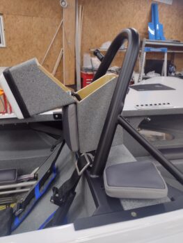
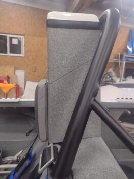
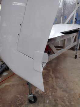
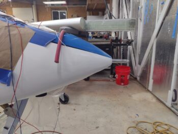
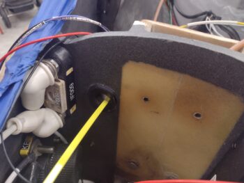
But I did pull the peel ply off the aft side rudder cable sidewall conical protrusions, on the right side (pic 1) and the left (pic 2).  This is of course the beginning of the end (or halfway… ahem) of my refilling and glassing the sidewalls where I extracted the rudder cable conduits.

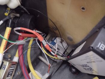
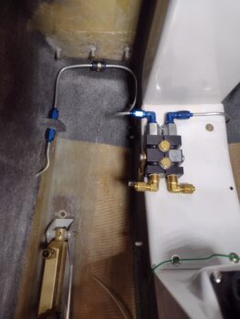
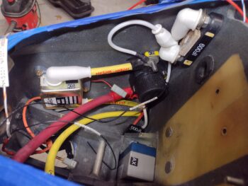
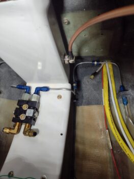
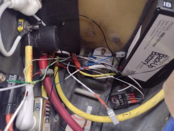
As I mentioned at the end of my last post, I pulled all the wires of the IBBS wiring harness out of the lower exit hole in the Napster bulkhead.  I chucked the rubber grommet that was inside that thru-hole and simply replaced it with a length of heat shrink (visible in pic 2).

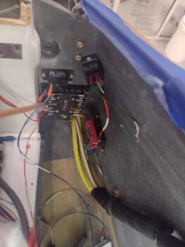
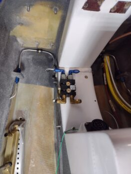
This allowed me to get ALL the terminated wires going forward and aft through the bulkhead wire transit hole… specifically the pair of power wires that are terminated with knife-splice connectors (center of pic 1) that connect the IBBS through-power to the X-Bus.  After connecting the knife-splices, I then secured and protected them with red heat shrink (pic 2).

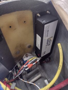
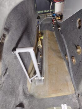
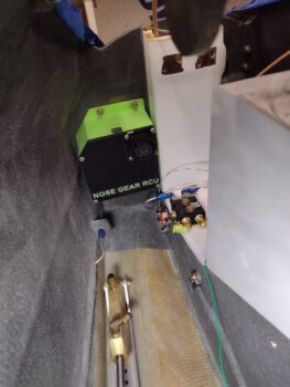
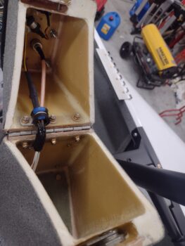
I then got to work on labeling and connecting up the taxi light wiring jack (next to IBBS, blue wire), the nose landing light jack, J0B (bottom center of pic), the nose gear’s small backup battery (emergency down if no aircraft power) pair of wires (green & white, left side of pic), and final switching circuit, power and ground wires for the taxi light stowed/ deployed actuator relay (RL011, bottom right corner).  I’ll note that except for one ground wire, and the pair of wires for the gear back-up battery, all wires are labeled.

Not shown is my work on the instrument panel mockup wiring, where I removed the outer heat shrink surrounding the relay that controls swapping between the COM1 and COM2 radios.  I had on my task sheet to verify that the solders were good, since they were completed with my old $14 soldering iron… not my “new” high speed soldering iron. Out of the 9 tabs, all but one looked fine.  The one tab that was a bit thin was an internal wire, but I got to it and got a nice clean good small solder blob on there.  Task complete.

Day 2, after another slow, lazy start, I was getting my task list finalized and confirming wiring and circuits before I printed out my wire labels.  I ran out of wire label heat shrink, but luckily the labeling heat shrink I ordered last week was in my mailbox.  Thus was able to do another batch of labels.

I then grabbed some coffee, fired up the heater in the shop, and was just getting ready to change into my shop clothes when I noticed a text from my local canardian buddy Guy Williams, who was going out for a quick hop in his Long-EZ and was asking if I wanted to go.

So I played hooky for a few hours and went out for a scoot up to Ocracoke Island and back.  Guy was testing out his old trusty Garmin 496 to drive his EZ Pilot autopilot for some upcoming cross countries that he wants to take.  He was having some issues with them talking to each other, so I had the stick and flew nearly the entire flight as he troubleshot the units.

After helping my wife and stepson assemble some Christmas gifts, I finally got back into the shop a bit later in the evening.  My focus was knocking out the heated pitot tube wiring.

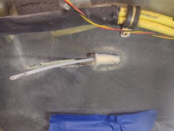
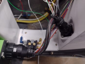
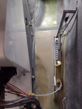
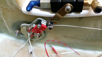
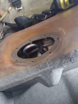
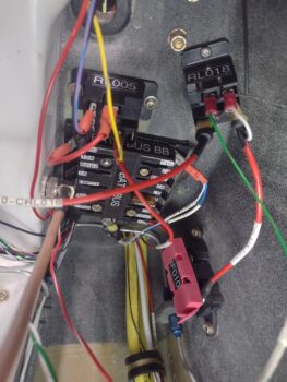
Here you can see the power wire coming off the top left corner of the Battery Bus terminated and connected to the Common terminal of the heated pitot tube’s relay (RL005).  Below this power wire input on the relay is the red power wire to the heated pitot tube (Normally Open tab) that enters the nose battery compartment with the other large power wires in the lower outboard corner.  Terminated on the same connector going to the relay NO tab is a yellow/blue wire that goes to the “PITOT HEAT ON” LED indicator light on the instrument panel.

And, again, I labeled all these wires.

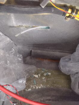
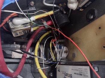
Not much extra to show you inside the busy nose battery compartment, except the new red heated pitot tube power wire, labeled but not terminated yet.  And the black heated pitot tube ground wire, labeled and butt-splice crimped/heat shrank to the heated pitot tube lead.  Both of these wires end in the lower right corner of this pic.

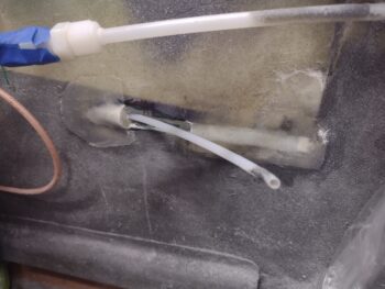
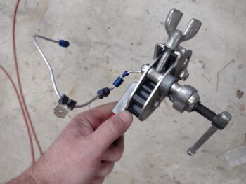
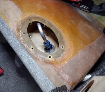
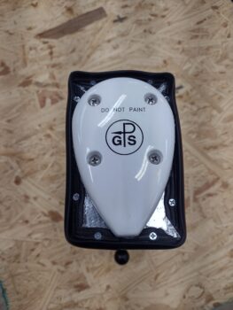
I then spent nearly half an hour slowly and carefully sanding the nose-tip end of the inside of the G10 tube that secures the pitot tube, since some paint got in there during painting.  I was able to get it, but not without making my pitot tube look a little rough in the process… I’ll need to buff it out to get it back to nice and shiny (before Marco, who made it for me, sees it!).

So… my nose battery compartment wiring is pretty much done, minus a couple of labels and a few FastOn terminals getting crimped on.

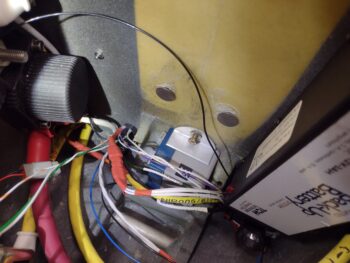
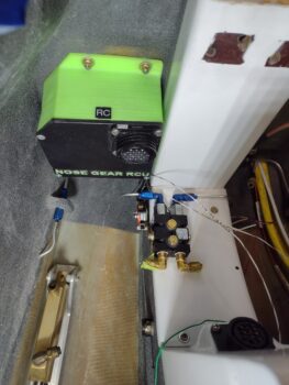
The last bit of wiring to add will be the 10 AWG cable from the battery contactor (on the exposed stud next to the “KB” on the yellow tab, lower left) to the Master Bus on the Tri-Paragon.  Cable #2 will be another 10 AWG size black cable from the battery’s negative terminal to the main ground bus on the Tri-Paragon.  The last wire will be the small power wire, that will connect to the Battery Bus, from an ammeter sensor on the 10 AWG Master Bus feed cable above.

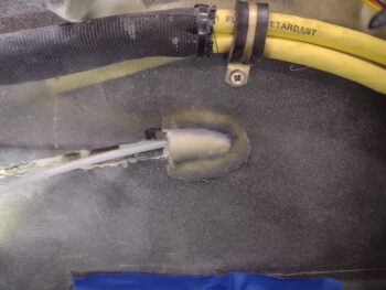
These 3 wires will all traverse the Napster bulkhead at the top transition thru-hole where the yellow zip-tie is shown.

Tomorrow, I plan on getting at least another round of layups done on the sidewall rudder cable conduit “trenches.”  I’ll also press forward with my nose area wiring as well as I move aft towards the instrument panel.

I’ll note that Jess and I are taking off to Charleston, SC to ring in the New Years the day after tomorrow, so that will be a good few days off the build.

Pressing forward!

Chapter 13/20/22 – Christmas Eve bits

Happy Christmas Eve my peeps!

I started off today sanding the minor half-conical external bumps where the rudder cable conduit exits the sidewalls much further aft than previously… at least 5″ further aft.  I sanded the pour foam to make the conical shapes, with the widest, furthest forward part of the “cone” consisting of the 1/16″ G10 “washer” that I embedded halfway into the sidewall, with the cable conduit transiting through the center of it.  I also sanded the paint around these conical bumpouts to allow better adhesion with the 2-ply BID layups.

Here we have both the right side (pic 1) and left side (pic 2) prepped for glass.

Which I did next, laying up 2 plies of BID on the aft EXTERNAL conical bumpout on each side.  I emphasize external since forward of the G10 “washer” I will make an INTERNAL conical shape (i.e. into the sidewall) with the widest part again starting at the washer, but then narrowing as it goes forward.  This will provide a scooch more space for the rudder cable spring to reside and better angle the cable for the rudder pedal conduit.

Again, peel plied 2-ply BID layups on both the right (pic 1) and left (pic 2) sides.

The outside temperature was a pleasant 60° F, but for epoxy work I wanted that bumped up a bit more.  So I turned on one of my Kerosene heaters and let it blast for a bit.

Since the shop was a good temp for layups, it was clearly a good time to do another epoxy-based task in adding a threaded RivNut to the upper right sidewall inside the nose’s battery compartment.  This threaded hardpoint will specifically be for securing the rather robust inline fuse that is for the hung starter warning alarm circuit inline fuse (I’m kind of wishing I had used an old-style glass inline fuse for this guy… these inline ATC fuse holders are quite chunky).

Note that I first swapped out the front top corner bolt that secures the starter contactor (anodized gold box) to add an Adel Clamp for the first inline fuse lead.  I then drilled a hole, prepped the RivNut and floxed it into the hole (pic 1).  Fast forward a few hours later, and here are the taped wide AN970-3 washer and greased-threaded screw removed, showing the RivNut floxed into place (pic 2).

Another hour’s worth of cure later I secured the inline fuse onto the sidewall… much better.  Yes, it’s very busy in this nose battery compartment, but let’s try and keep it all as tidy as possible, shall we?!

While all the layups and flox were curing, I took about half an hour to gather up my tools and hardware to install the right rudder into the winglet.  You can clearly see it hanging open a little bit, as I need to remove it and sand some internal mating surfaces down at the bottom inside rudder and pocket for it to close all the way and seat in place.  Paint, once applied, has a way of making tight surfaces get knocked even further out of spec tolerances and such is the case here.

Also note that I installed the Nav/strobe light mounting plate on the forward wingtip.

Another quick kill task was lopping off the way-too-big diameter stock terminal connectors for the CTEK battery charger leads that are getting permanently connected to the battery with the pairs’ quick disconnect connector.  I sized the correct FastOn ring terminals and then crimped them on, replete with the correct color heat shrink applied… of course <wink!>.

My last task of the evening was running the wiring bundle through the transit hole at the bottom of the Napster bulkhead before installing the TCW Technologies IBBS (Integrated Backup Battery System) unit.  To be clear, this wiring will need to be pulled out to allow me to widen that wiring transit hole, as it needs to be just a tad bigger in diameter to fit all the wires exiting and entering the nose battery compartment.

And with that, I called it a night.  If I get a chance tomorrow, Christmas Day, I’ll shape the forward rudder cable conduit sidewall channels and get those glassed.

Either way… moving forward!

Chapter 13/22 – The NON-Midas touch!

If you asked me why I didn’t rig the rudder cables up to the rudder pedals while I had the wings on the bird and it was unpainted, I wouldn’t be able to tell you.  My guess is that I was still waiting to research and discover the final intel on the springs I brought up last blog post.

I also think I lumped the task of rigging the rudder cables in with finalizing the plumbing of the brake lines, since this involves my pedals as well.  The bottom line is that hindsight is 20/20, and I am wishing that I would have done this task at a more opportunistic point in the build.

It certainly would have been significantly less nerve-racking, as cutting into the sidewall with the ever-present threat of going too far and messing up the exterior paint just adds to the annoyance of having to cut out the rudder cable conduits to get them to exit out the sidewall farther aft, to allow space for the springs to be installed.

Here I’m in the process of exposing the right rudder cable Nyla-flow conduit, which I cut out about 1-2″ of wall at a time since it has a slight up angle as it travels aft, and the short cutouts allow me to adjust fire as needed.

I realize “normal” builders wouldn’t have to mess with this because normal builders aren’t as “special” as I am (haha!) by burying their rudder cables into the sidewalls.  Nor do normal builders buy rudder/brake pedals with the claim that they don’t need springs (they probably, but not definitely, do…).

Here we have the initial mark and cut on the left sidewall (pic 1), followed up by another cut mark a few iterations later (pic 2).

After I got the rudder cable conduits exposed and popping out of the sidewall farther aft, I then drilled and crafted a couple of 1/16″ thick G10 phenolic “washers” that I slid onto each tube, and slid into slits I created about a 1/4″ high on the top and bottom of the channels I made to remove the conduits (you can see this in pic 2).

I then used foam scraps and micro to secure the conduit tube aft of these embedded washers, filling the cut out channels back to level with the sidewalls.  After they cured for about an hour, I then used a bit of pour foam to fill in aft of the protruding “washers” which will allow me to shape the foam into half conical bumps on the sidewall.

It was getting late, so I left the rudder cable conduit pour foam to cure overnight, and got busy working on the electrical system.

See the inline fuse at the bottom of the battery compartment labeled IF000… about the middle of the pic?  The orange and red wire coming out that heading aft is the SD-8 backup alternator feed wire from the control relay in the Hell Hole, that in turn is connected to the SD-8 electronics in the GIB headrest.

Since I’m just now installing the nose battery compartment components, not surprisingly that wire was in 2 parts, one front and one aft, and needed to be joined together.  I used a butt-splice connector and spliced the wires together before adding heat shrink (pic 1).

I then used some anti-chafing heat shrink wrap (that I failed to slip on before I installed the contactors) that I simply zip-tied to the wire bundle to protect it (pic 2).

My last task of the evening, which should have taken half an hour tops, was installing the battery bus, the mini ANL-15 fuse, the RL005 heated pitot tube relay and the RL018 relay that connects the E-Bus to the battery (unswitched) side of the battery contactor AFTER the SD-8 backup alternator is online and the main alternator is offline (and the main bus too).

I have 4 embedded platenuts in a raised pad on the aft side of the Napster bulkhead.  Well, right off the bat one screw wouldn’t thread in.  On further investigation I still had some Saran wrap plastic in there that I used to protect it while glassing it.  However, the threading never worked, and it’s just not deep enough to get a tap in there to clean up the threads.  I ended up drilling out an initial hole and have a 4-40 screw in there currently.  This whole debacle ended up taking well over 2 hours.

Later I’ll drill that top hole out and mount a #10 screw with a nut on the front side of the bulkhead.

Ok… still… Pressing forward!

Chapter 13/22/26 – Upholstery finé!

Yet another 2-day update here…

I started off Day 1 checking a number of various electrical data points, including verifying and changing a couple of components connected to the Battery Bus.  The primary component swap was pulling the fuel pump off the battery bus and placing it on the E-Bus, swapping it with the Pitch Trim System.  My thought process was fairly simply: what switches might a kid sitting in my bird, unattended, start flipping.  And also, what might I leave on connected to an always-hot buss?

The pitot heat relay and wiring is physically close to the battery buss and thus connected to it.  I considered moving it off of it as well, but it has 2 fail safes with both an indicator light and, more importantly, a 40-knot airspeed switch to allow it to power up (specifically to keep it from staying on if the master were to be left on, or in this case just in general).  Now, while the fuel pump does have an indicator light and a flip-up switch cover, I felt it the worse of these 2 evils to be connected to the Battery Bus.

I then got to work repairing a triplet of cables that ripped out of a terminated pin on the aft primary nose gear actuator connector.  To repair it, I crimped the 3 wires into a much larger single wire and then terminated it with a pin that was then set into CPC (Circular Pin Connector) P1 on the front of the NG30 cover (that is now installed).  I also finalized installing the wire-securing clamps on the back end of these two nose gear connectors.

I then spent nearly an hour going through the rats’ nest of wires to get them somewhat sorted out, and out of the avionics bay and NG30/canard area so that I could climb into the bird to verify the rudder/brake pedal installation positions.

Of course to do that, I first needed to install the front/pilot seat cores, which I did in final fashion by thoroughly cleaning up the seat pan and seat back before pulling the tabs off the cores’ Velcro strips and mashing them all into place…. including the right armrest pad.

This concludes yet another major milestone on this build since it officially closes out Chapter 26 – Upholstery and places it squarely in the COMPLETED column!

This allowed me to install the rudder/brake pedals and get a good idea of where they needed to be installed, which I did an initial temp install before calling it a night.

The next morning, I pulled the 1/4″ tubing fittings out of the rudder/brake pedals’ master cylinders to install 1/8″ fittings for the Nyla-flow feeds from the Parking Brake Valve.  The aft fittings on the master cylinders are 90° 3/16″ fittings that will connect to the separate brake fluid reservoirs.

That all being said, note the exit point of the in-side-wall rudder cable conduit at lower left in the pic below.

First, here’s another shot looking from the forward nose end of the left rudder/brake pedal with the 1/8″ Nyla-flow tubing from the Parking Brake Valve (aka wheel brake caliper) into the master cylinder.  The aft (upper) 90° 3/16″ Nyla-flow fitting is currently not connected.

Now, again, note the 3/16″ Nyla-flow rudder cable conduit exit out of the left sidewall, in the very upper right of the pic below.

I pointed out the rudder cable conduit exit on the sidewall to discuss a requirement that comes with installing the Hidden Bellhorn on the rudders: a spring that allows for continued movement of the rudder cable after the rudder’s hidden bellhorn hard stops against the internal wall of the rudder.  The claim is that without this spring that you may not have any forward movement on the pedal to then engage the brakes [To be clear: the Long-EZ’s rudder/brake system is set up that the rudder must be fully engaged before any braking action <continued pedal pushing> occurs].

About 2 years ago I spoke with the manufacturer of my rudder/brake pedals, Dale Martin, about his original statement to me that with his pedals we don’t need these springs.  This is why I exited the rudder cable conduits out of the sidewall where I did. Moreover, we discussed how little forward movement on the pedal is required to activate the brakes after full rudder deployment (around 1/4-1/2″).  Also, there are a distinct few builder/fliers out there (Wayne Blackler, Klaus Savier, etc.) that do not have these springs installed out of personal choice (more direct rudder response, for one) and have had no braking issues to report.  Conversely, Marc Zeitlin considers them mandatory.

In assessing the requirements levied against us builders in the hidden rudder bellhorn plans, I decided after re-reading these impassioned arguments on the COBA forum that I would simply split the middle… literally.  I spent a good deal of time on the Century Spring website as well as McMaster-Carr looking at the specs of various springs (which are given in these instructions… upper right of background sheet), before deciding to simply cut an extra spring I had on hand in half and press forward in my heretical shenanigans (the 2 full ones are from the Cozy Girrrls).

Not surprisingly, the Cozy Girrrls got a little fancy with their springs by adding a washer on each end that they then terminate the 0.05″ wire back into.  Since I cut one spring in half, one end of each of my springs now has non-flat/grounded ‘free-radical’ spring coil on it.  Thus, I copied the Cozy Girrrls and drilled out an AN970-3 wide washer to cover these ends… now a distinct characteristic of these abominations that I created.

I’ll note that a full-length spring (3.75″) can be compressed by 1.75″, but the specs states that normal compression should be no more than about 0.8″.  Now, if we halve that we get a normal compression of over 0.4″, but if needed over double that. The numbers show this will provide more than enough throw past normal operating parameters in case a mushy brake (air in the lines, etc.) is encountered.

Finally, I grabbed this pair of pics below to show the amount of rudder conduit that would have to be extracted from the sidewall with the standard spring length (pic 1) as compared to my new “petite” spring (pic 2).  Clearly a lot less work with the petite spring in getting it installed.

They say confession is good for the soul… so here’s my confession.  And with that, as par usual, I’m pressing forward!

Chapter 13/22 – Parking brake installed

Crazy that it took me about 7 hours to get all this done… of course, I had planned on getting much more accomplished than I did.

First, I watched a couple of videos on Flaring tubing and also did a review of the Matco emergency brake specs and installation, including a good video on that as well.

The flares on the right side brake tubing cross-connect, which I did after the left side, were much better than the left side’s.  Thus I cut a new length of tubing and remade the left side with much better flares.  I then did the final install of the left side aluminum tubing brake line cross-connect to the parking brake valve (pic 1).  I then did the final install on the right side brake line cross-connect as well (pic 2).

I then installed the Parking Brake engagement handle . . .

after I installed the parking brake ON indicator light microswitch (close up below).  After getting the handle cable installed at the correct engagement length in the parking brake valve lever, I did the final install of the Nose Gear RCU (Relay Control Unit) that was awaiting all the brake line cross-connect shenanigans to be complete to allow its installation.

Here’s an old closer-up shot of the microswitch that powers the panel “Parking Brake ON” LED indicator.

And another closer shot of the forward left NG-30/aft Napster bulkhead area.

And a video I shot 8 years ago showing the parking brake handle cable functioning:

Yep, slowing inching forward!

Chapter 13/22/25 – The Big Swap

Again, a 2-day post here . . .

Day 1 was the big swap.  I loaded up the canard this AM and with the “outboard wing” (now canard buffing) sawhorses that I reinforced with cross-bracing loaded up last night, delivered the canard to Phil’s shop.

I met Guy there where he helped me load up the right wing in the trailer, while we placed the top cowling in the back of his covered truck bed.  I also had the aft nose/avionics cover in my truck cab.

After delivering all that back to my shop…

we then loaded up the left wing in the trailer and the bottom cowling in his truck and delivered that to Phil’s shop.

Here we have the left wing in Phil’s shop.

And a wider view of the canard and left wing at Phil’s shop.

By late into the evening I had finished cutting and terminating the big yellow starter cable in the nose and installing it onto the bottom terminal of the starter contactor (anodized gold box center left of pic), which in turn has a big yellow cable that connects to the battery contactor (middle, black cylindrical).  I also mounted the ANL-40 inline fuse block and connected the B-lead from the alternator to it, and from it the cross-connect cable to the battery contactor.  All in the forward nose battery compartment, of course.

Day 2: Phil had some slight break-throughs on the canopy’s blue paint, so this morning I mixed up a small amount and took it to his shop and spent a couple of hours touching up those break-throughs.

Here we have Ray in the foreground working on the canard, with Phil behind him working on the left wing.  Behind Phil is the canopy, ready for its final buffout and ceramic coating after a minimum 24-hour paint cure.

Back at the house I spent a couple of hours in CAD drawing up this seemingly simple protective cover (from fingers touching a potentially powered circuit) for the ANL-40 inline fuse.

My dimensions must have been spot on since this is the first and only 3D print I did of the protective cover… here being test fitted into place.  I’ll probably Velcro it to the Napster bulkhead and call it good.

I then got busy fitting, cutting and flaring the 1/8″ 3003 aluminum tubing for the forward brake line cross-connects.  I had already made these before, but lost them either in moving down to NC or in the hurricane/tornado that hit my hangar back in 2019.

Here is the initial fitting of the 1/8″ 3003 aluminum tubing forward brake line cross-connects for the left side (pic 1) and the right side (pic 2).  I need to get the brake lines installed and square away before I start running wires aft of the Napster bulkhead.

Pressing forward!

Chapter 8/19 – Pilot headrest installed

The past couple of days have resulted in yet another couple significant milestones in that both the GIB seat cores and the pilot headrest are installed in the bird.

Here we have the pilot headrest no-kidding bolted in place on the pilot seatback, with the upper and lower headrest pads attached and the GNS-480 GPS antenna puck covered with a nice spiffy white radome.

On the upper back side of the pilot headrest one can clearly see the “Big Brother” aft-facing wide-angle spy camera to keep tabs on any back seat suspe— er, ah, passenger!  And to have a good view of top cowling engine/prop stuff (hopefully never needed for that purpose!).

Here the pilot headrest is open for storage access (pic 1), where you can also the camera wires and GPS antenna cable (pic 2).

I officially finished off the back seat upholstery by installing the armrest pads (pic 1), where the right side will be most likely removed often (pic 2), to gain access to the decent-sized storage compartment under the pad, in the armrest (pic 3).

In prep for swapping the left wing out for the right wing at Phil’s shop tomorrow, I finished cutting and adding Thermo-Tec inside the wing root.  After the physical application of the Thermo-Tec was completed, I then used my gray hi-temp RTV to fill in the joints, seams and edges to avoid any dirt and oil from getting up underneath the Thermo-Tec.

And with that, I called it a night.  Lot’s of logistics going on tomorrow!

And, as always, pressing ahead!

Chapter 24/26 – Headrest pads installed

Another 2-day post here…

First off, here is a shot of the back seat area with the GIB headrest pad in place… honestly, I don’t remember if it was actually mounted or not.

But it definitely is mounted here below, as is the pilot headrest lower pad… both pads secured with #6 screws.

Also note the GNS-480 GPS antenna atop the pilot headrest is covered with a painted 2-ply fiberglass radome…. just to make it look snazzy.  Gotta have some fun with this stuff!

Here’s a side shot of the pilot headrest mounted lower pad.  It looks good secured to the surface with the aft side nice and flat.

I made a video on how I mounted these pads, which is something that would have been helpful to me when I was figuring out how to do it.

Lastly, here is a quick shot of the left rudder gust lock, painted, and a quick fit check.  The paint needs some cleanup, but besides that it is functional.

Again, pressing forward!

Chapter 8/21/26 – Hydramats & Rollbar

Today was yet another busy day just getting a bunch of tasks done to get this bird in the air ASAP.

I started off by removing the tape from the just painted, labeled and clear-coated keys (pic 1).  I then separated them into pairs, added the labeled gas keys and put them on their respective rings: one primary set of keys with the red tag, and one backup set of keys (pic 2).  Keys are done… pressing forward!

My next task (later below) was actually shooting clearcoat on the rollbar… for clarity I grouped that together later on.

I did a good bit of painting and RTV/Permatex #2 work today because the next few days will be VERY cold… below freezing.

I taped up, mounted and degreased the CS spar bolt hole opening covers and the left rudder gust lock before shooting them with sealer first, then a couple of coats of white paint.  Not perfect at all, but will do the job.  Note that with the excess white paint in the cup, I taped and touched up a couple of the left vortilons to finish the touchups required on those.

Today was the day to knock out the installation of the Holley Hydramats in the GIB thigh support sump tanks.

I started by cutting new full sized gaskets for the underside of each cover.  Versus the old oval “ring” style, I’ll note that a full gasket eliminates a possible exit point at the upper inside seam of the oval gasket.  After cleaning the underside of the cover with Acetone, I slathered Permatex #2 on both the gasket and the cover and clamped them together.  The bare cover and gasket to the right is the right side cover waiting to have its gasket attached.

I cleaned out each sump tank with Acetone, let it dry and then vacuumed it to get as much dust and debris out as possible.  I then installed the left tank Holley Hydramat.

And then the right tank Hydramat.

See what I call the “Madonna Bra” looking thing on the front wall of each thigh support sump tank?  I grabbed this shot to show this . . .

And then the inside of the sump tank.  That’s a low level fuel sensor that will ring off if the fuel ever drops below that level inside the sump tank.

Here we have both Holley Hydramats installed inside their respective left and right sump tanks, and the covers and gaskets secured in place, with all the excess Permatex #2 that I slathered on the edges removed and cleaned up.

Again, here we have my FIRST task of the day, but I forgot to grab a pic of the roll bar until much later, with other components in the shot.  Easier to just report on it here.

First, here is the 2K matte clearcoat that I dropped a pretty little penny on this morning at NAPA.

It did a great job in giving the roll bar a nice black sheen, but not too shiny as to blind the GIB when the sun hits it.  Note the white painted stuff you saw earlier, but also to the left is the pilot headrest with shot bags on top of the white painted “radome” that covers the GNS-480 GPS puck . . .

Which I installed with new, longer stainless steel screws that I also picked up on my quick shopping run this AM.  I actually did the initial drilling and screw-setting on the perimeter seal last night, but today I trimmed it so that the GPS puck was not on the seal edge, but firmly mounted and touching the ground plane.

The final install of the seal, which is a shape turned sideways (90°), has RTV on both the top interface and along the side edges of the headrest.

I then RTV’d the top side of the rubber seam and popped the radome into place.  After cleaning up the excess RTV, I weighed the radome down with shot bags and tightly taped around the seal perimeter (shown in pic above).  Tomorrow, after cure, I’ll of course remove the tape and shot bags.

I checked the tech sheet on my matte clear coat and it states that it dries extremely fast.  With that info I proceeded to mount the upper seatbelts and then install the roll bar.  In hindsight, I’m wishing I would have waited 24 hours since I had a few spots that showed the paint/clearcoat was still a bit too soft.

Regardless, the roll bar with the upper seatbelts attached is installed (pic 1).

Now, before I installed the roll bar I actually installed the GIB armrests and then did the “final” install of the GIB seat cushions… meaning I pulled the wax paper off the Velcro strips and no kidding set them in place and then sat on them for about 15 minutes to set the Velcro adhesives as best possible (pic 2).

One last shot of the final install of the roll bar.

Yep, slowly moving out on this beast to get ‘er in the air!