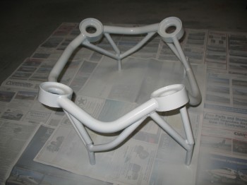
Tonight I finally rolled up my sleeves, grabbed a can of WD-40 rust remover, my disposal econo-pack of wire brushes from Harbor Freight and went to work.

Tonight I finally rolled up my sleeves, grabbed a can of WD-40 rust remover, my disposal econo-pack of wire brushes from Harbor Freight and went to work.
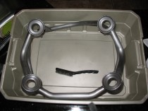
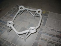
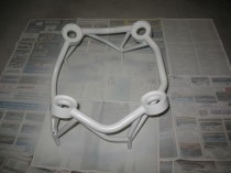
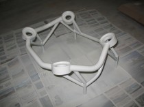
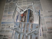
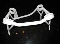
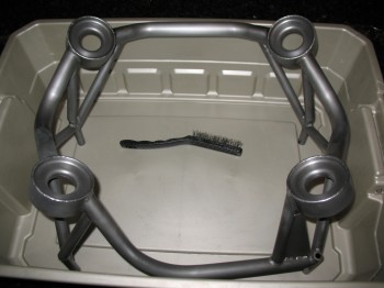
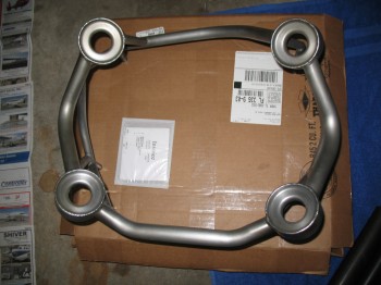
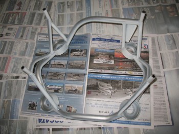
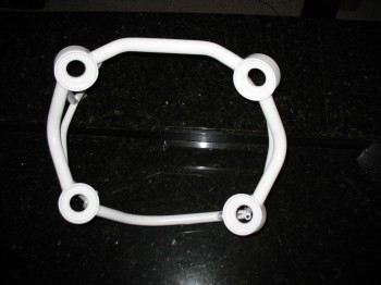
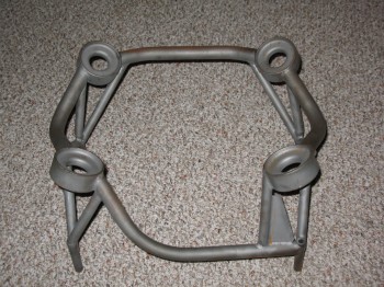
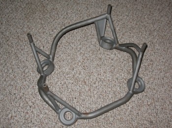
I found Randi & Chrissi of Cozy Girrrl fame today to pick up my engine mount that I had ordered from them last month. Looks good. I think the humidity and the amount of time between it getting built and me picking it up allowed some surface rust to form a bit. No worries, I’ll knock that off and paint it so it will stay corrosion free until I use it.
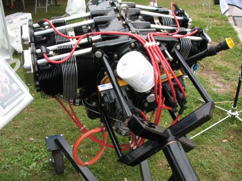
Today I got to see & touch a real ECi IOX-340S engine! This will be how mine will look in general.
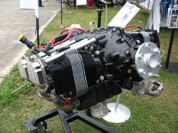
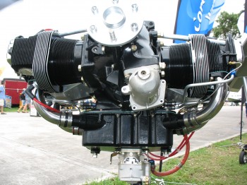
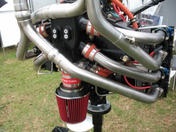
Below you can see ECI’s cold air induction system on I believe an IOX-360. Notice on the IOX-340 above they have have the normal oil sump without cold air induction.
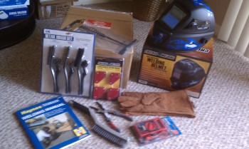
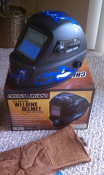
This post covers the past month or so of welding endeavors. I signed up for a class at the local adult learning annex that covers mainly stick and TIG welding, with a little MIG thrown in there as well. Of course, with all my welding stuff literally scattered across the globe, I ran to Harbor Freight to pick up some less expensive gear. Their welding helmets got great reviews online and I was able to pick up a $79 version on sale for $39, so I was fairly pleased. It works great too!
(BTW, sorry for the blurry pics, my camera has been a little funky lately… but considering it’s lived through Afghanistan deployments, being dropped off Mt. Kilimanjaro & is now slathered with epoxy as the official build camera, it’s not doing TOO bad… I hope.)
More after-Christmas presents!
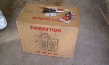
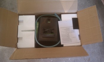
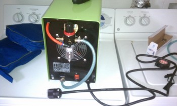
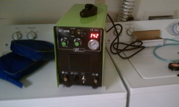
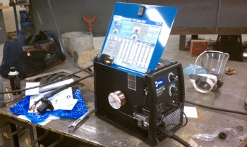
 I spoke with my welding instructor about using my own welder, if I was to get one, and he was very agreeable to it. He told me that it would need to be dual voltage because the 220V power at the school was 3-phase. So dual voltage was definitely a requirement. I was able to pick up a cheaper TIG welder that got great reviews off eBay (after a ton of research) for less than $400 with shipping. I received it in good shape & unpacked it . . . all the components looked to be fairly good quality (not uber high end, but sturdy).
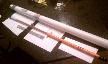
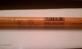
I also picked up some TIG welding rod.
I had to add my own power plug. Since I can only use 120V at school, I installed a robust plug from Home Depot.
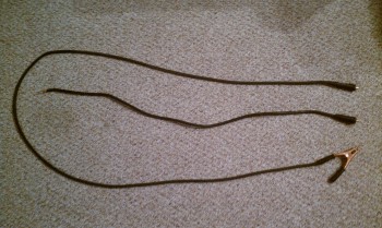
I also went to my local welding supply and had them make me a new grounding clamp cable. It’s over double the length of the one that came with the welder.
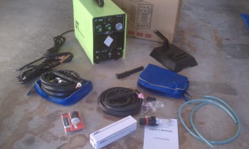
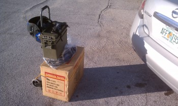
 Below is my “kit” that I used to haul my welder to/from class a couple of nights a week.
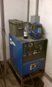
Of course my portable welder is a far cry from the monsters they use at my welding class, and the welding station setups they have for handling big chunks of metal!
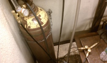
The best part of this welding class is that I could use all the Argon I wanted each night of class!
Below is my first weld using TIG. I ran this bead without welding rod filler, since I was just trying to get the motion down at first.
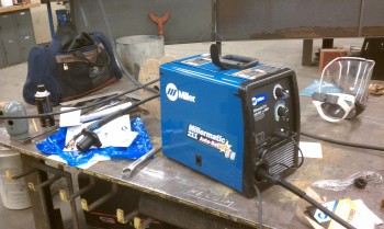
One of my classmates picked up a Miller MIG machine right before class ended. A very nice machine (my MIG welder in storage is an eBay special like my TIG).
I went ahead and just lumped all my acquired bounty into one post for the month of January. Obviously, while I’m here in Tampa and my project is back in Germany, there’s not much building going on. There is however, a whole lot of time to design my electrical system and other major end items, and actually think a bit on each component, have some lengthy discussions on them, and then make some purchases.
One such item was my wheel pants. I was told by a few of the Old Guard that Sam James makes some great wheel pants. So I caught up with him at an EAA breakfast in Ft. Meyers a few weeks after I ordered them and picked them up. The wheel pants are sized for a 500×4 Lamb tire. Again, trying to keep things light!
I also took the opportunity while in Florida to pick up my canopy from Todd Silver in Ft. Lauderdale (there’s a lot of forts in Florida, eh?). Another nice guy!
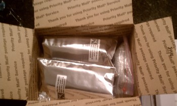
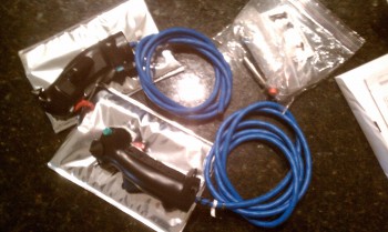
After a few discussions with JD Newman, I figured out all my buttons & switches (I think!) and then ordered my Infinity stick grips. Very nice grips! And pre-wired too!
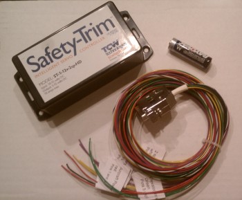
 I ordered a fairly new-to-the-market 2-speed trim controller from TCW which was made specifically for heavier duty trim actuator motors (read: NOT Ray Allen servos!). Also nicely packaged and looks to be good quality. I had a few long discussions with the TCW bubbas about their different products, and these are some pretty smart guys!
Along with a new Starter Contactor, I also picked up a new Master Battery Contactor: the Gigavac GX-11SA. Why? Well again, in my discussions with the electrical gurus, I realized that to keep as light as possible in my build that I want to utilize B&C’s L40 40 Amp alternator, which is about as light as you can get in alternators (vs the vacuum pad designs). Thus, I need to conserve amperage anywhere and everywhere I can. The standard battery contactor takes about 1 Amp to keep the contactor closed and electrons flowing. The Gigavac GX-11SA has a special internal circuit that once the contactor closes and the circuit is completed, it keeps the contactor closed for less than 1/10 of an amp (0.090 to be exact). So, for the same contactor weight, I gain 0.9 of an amp. Doesn’t seem like much, but when you only have 40 amps to play with, and a decent amount of “electro-whizzies” (as Bob Nuckolls calls them) that you’re using in the cockpit, you want (I want) as much spare power as possible. (The pic below is not my actual Battery Contactor, but a representative one… just as I did for my starter contactor).
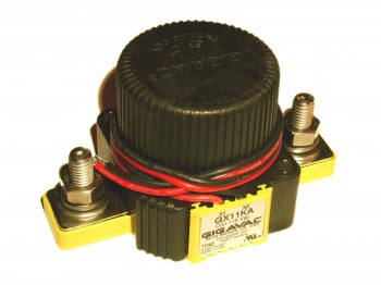
Is there a down side? Yes, there is a slight bit more electrical noise, but according to Bob Nuckolls & Eric Jones, it’s negligible. (The high efficient internal coil is shown at lower right in the diagram below).
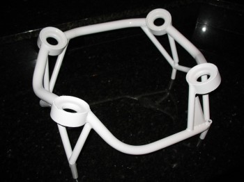
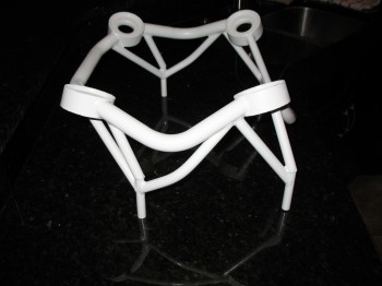
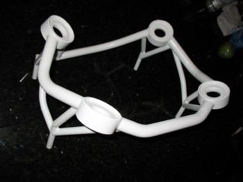
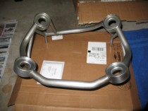
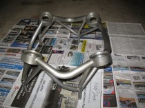
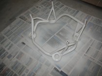
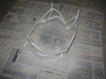
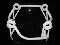
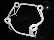
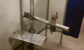
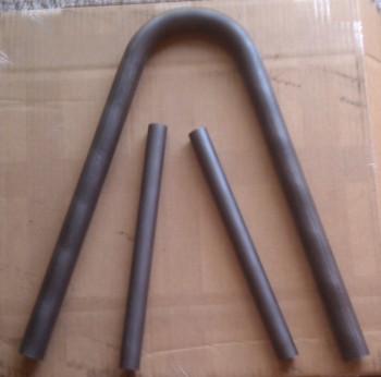
Finally, below is a shot of my roll bar and my support down-tubes that will tie in the roll bar to the base assembly. I was originally going with a 0.1″ thick steel plate for the base that would travel from one longeron to the other, but that’s too heavy, especially if you add any cross support tubes to the mix (see my diagram with a couple square tubes under the steel plate). So right now I’m looking at having one rectangular-tubed cross support and taking my vertical support down-tubes from the back of the roll bar straight to the rollover assembly side supports on the longerons to eliminate a second/rear cross tube (which is the way many people build it). This will further eliminate some weight.
Well, this will definitely be my last post for 2012 . . . it’s been a very busy year for this airplane build. Hopefully 2013 will be just as productive!
I’ve been playing around with the design for my rollover assembly. I’m looking to take a welding course while I’m in Tampa to focus on TIG (I already own Stick & MIG welders and have welded a fair amount) & possibly the EAA TIG welding workshop in Georgia.
In the meantime, as I mentioned I’ve been working through different designs on my rollover assembly, which I’ve included some scribblings on it below:
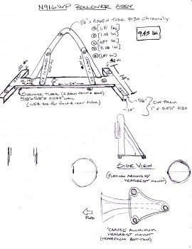 This is certainly not the final design I’m sure, but it gets me moving in the right direction and thinking about it.
Happy New Years!
My Christmas present to myself this year was the B&C SD-8 back-up alternator that I’ll be using in Bob Nuckolls’ Z-13/8 electrical system design.
The SD-8 is mounted on the engine’s vacuum pump pad and is used as the primary source of power for the endurance bus in a two-layered electrical system, if the main alternator should fail.
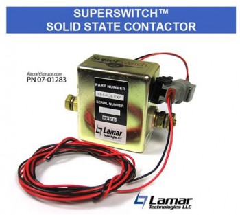
I forgot to add a picture of my (new & improved) Starter Contactor. After a fair amount of research, and talking to some very smart electrical dudes, I’ll be using the Lamar SuperSwitch Solid State Contactor for my starter contactor. From what I understand, these contactors were originally made for the Lancair Columbia aircraft and were apparently made in a decent quantity so that when Cessna bought the Columbia from Lancair, they swapped out the starter contactors and Lamar had a ton left over. So Lamar basically just dumped the remaining contactors for comparatively nothing on Aircraft Spruce. I didn’t take a pic of mine, but this is what it looks like. BTW, I don’t think the P/N in the pic is good any more since I believe ACS sold out their stock of these contactors.
The reason behind moving to solid state is that it has no mechanical moving parts, and is significantly more efficient than traditional starter contactors at a fraction (1/3) of the weight.
Instrument Panel
Ok, since before I left Germany I have been working on my electrical system design. I’ve read & re-read Bob Nuckolls’ book, The AeroElectric Connection, which I think most homebuilders would agree–even if they don’t use his designs–that it’s the homebuilder’s electrical Bible.
Of course much of my electrical system design is wrapped up in the instrument panel components: how much current does each component draw? what’s my fault tolerance and mission profile? In short, what do I need, and how many of ’em do I need to feel comfortable? The design and warm fuzzy factor is of course different for each builder.
I spent a good few weeks researching all the options that I saw as viable solutions for my Primary EFIS, a back-up EFIS, an engine management system, back-up instruments, radios, etc. Basically anything that would go on my instrument panel. I built a big matrix and essentially had a run-off of just about every system out there. I also talked to a myriad of people about their take on panel designs. I called, e-mailed and pestered just about every vendor out there for information. I looked at a lot of company’s stuff, and here’s a list of the main ones I focused on:
• Dynon
• GRT
• AFS
• G3X
• TruTrak
• MGL
• TCW (back-up battery system)
I may have looked at some others, but the list above was the main jist of my focus. In my matrix, I really focused on requirements, or in other words “needs” vs. “wants.” I also looked at current draw, weight, size, ease of use, capabilities, features, interoperability, scalability, cost, etc. It made me take a hard look at what I thought I was going to put in, and what I COULD put in. In the end, if you look at the initial pics I took in my project preparation, you’ll see it looks a whole lot different than the latest thoughts I have on the panel design. I say “thoughts,” because I still have a fair amount of time before I have to buy any panel components, and technology is always changing. So here’s the latest generic version of my panel:
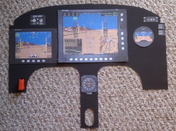
As you can see, the end result of my run off and what spit out of my matrix was Grand Rapid Technologies new 10.4 inch HXr EFIS. The “r” on the end of HX stands for remote. It allows almost every traditional panel component: radios, transponder, audio panel, etc. to be placed behind the panel and tied into & controlled by the EFIS. Another 2 capabilities that factored into my decision was the GRT’s Altitude-Heading-Reference-System (AHRS) box with it’s not requiring GPS input to function as designed… And GRT’s engine management system is rock solid and is the same one used in countless homebuilts. It’s the same engine management system box, it just gets tied into the EFIS (also remotely) where it displays data graphically. In addition, a couple of bells and whistles admittedly helped win me over as well. I really like GRT’s HITS (Highway in the Sky) feature on their EFIS where you essentially fly through the boxes to get the plane on the ground, and their focus on IFR operations. Finally, GRT seems to play a lot nicer with other vendors out there, so they work with a lot more 3rd party market stuff (GPS, ADS-B, Radios, etc.).
Btw, the instrument panel is covered in Chapter 22 of the plans, which is the Electrical Section.
Rudder & Brake Pedals
The Rudder Pedals are covered in Chapter 13 of the plans, Nose & Nose Gear. The Master Brake Reservoirs were covered in the chapter on the firewall (Chapter 15) because that’s where they were originally located.
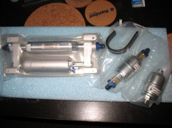
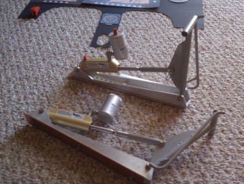
Many early builders, including Debbie Iwatate, moved the master brake cylinders off the firewall, putting them up front either on or near the rudder pedals. Ken Miller & Dale Martin have perfected this design and sell it in a nice package as shown in the pic below. It’s a bit expensive, and I probably could have made them myself, but time is money to me and these are nice. Plus, Dale includes specific instructions on how to install these guys so as not to bungle anything up! One really nice feature on these, besides getting your brake cylinders (and thus weight) off the firewall, is that they are adjustable, so you could move them farther or closer to pilots of various heights.
This will probably be my last post from Germany until next year since I leave tomorrow for Tampa.
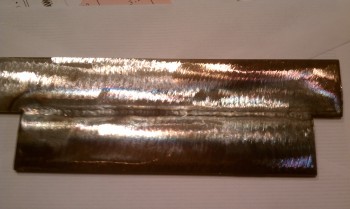
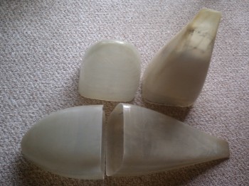
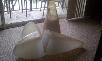
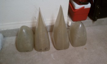
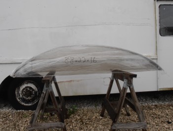
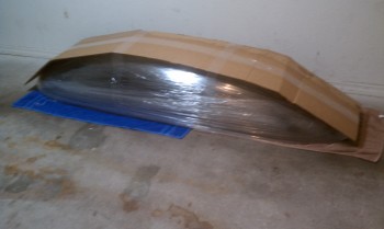
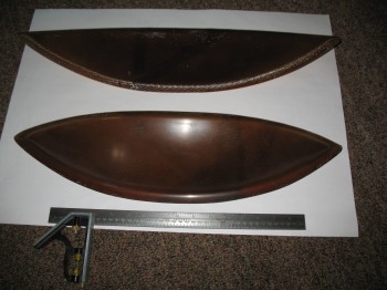
I thought I would show a picture of the fuel blisters that I just recently received from Feather Light. I’ll be real happy when I’m posting pictures of these guys installed!
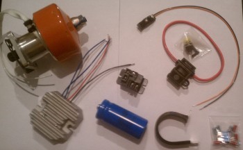
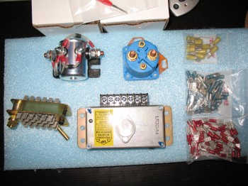
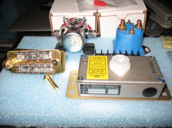
Tonight I took some pics of some of my electrical components that I received from B&C Specialty Products.
Pictured below is the master battery contactor (silver), the starter contactor (blue), the firewall ground “forest of tabs,” and the B&C LR3C 14v Voltage Regulator. As well as an assortment of FastOn terminals.
And below is the EFII Electric Fuel Boost Pump with filters that I recently received from ACS.