Chapter 23 – Dialing in exhaust brackets

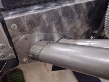
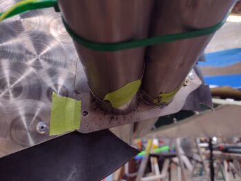
Today I finally got the right side exhaust pipe brackets dialed in to a point that allowed me to re-plasma cut them out of 0.036″ 316 stainless steel.

But first, after spending another couple of hours dialing in yesterday’s scrap steel test brackets, I then traced them onto cardboard with any required corrections added in.

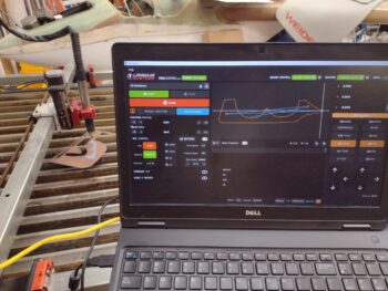
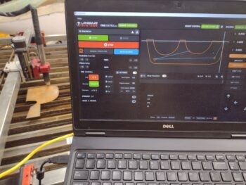
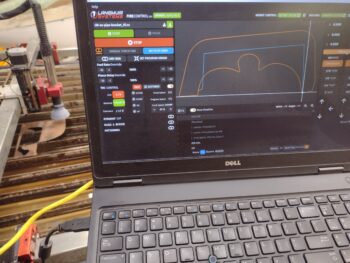
After ensuring the latest cardboard bracket mockups fit well, I then scanned them into Fusion 360 CAD and remodeled them for plasma cutting out of scrap steel, which I’m doing here:

I soaked the test brackets in white vinegar in my “parts cleaning bin” outside for a good bit to allow easy cleaning off of the rust.  When I went to check on the brackets I found this cool looking butterfly sitting on the edge of the plastic container.  It flew a few feet away, but I zoomed in and a grabbed a shot… something to break up the hours of working on these damn brackets!

Also while the brackets were soaking, I gathered up and cleaned up my welding helmets before performing a quick ops check on each one.  My nicer, older, more expensive blue one (left) failed the ops check, and will need a new battery (I ordered an external battery holder to allow me to change it whenever I need to without having to crack open the sealed lens unit… a common hack for these helmets. Note: a lot of newer mid-price-range helmets now have easily accessible compartments on the lens assemblies for replacing batteries).

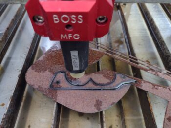
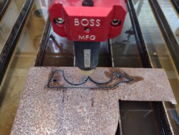
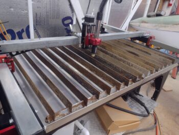
Back to the right side exhaust pipe brackets.  After cleaning off the minimal dross and the surface rust, I then spent about 45 minutes doing a final dialing-in on the top steel test bracket.

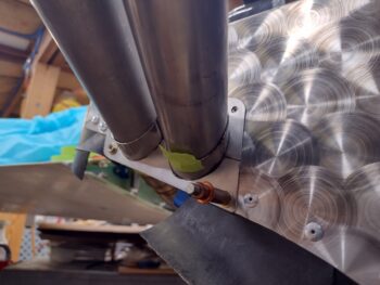
And then the same for the bottom bracket.

Now an aside: Jess noticed that her linen closet ceiling either had a foot crash through it from the attic or it simply caved in on its own, so after an investigation and some measurements a few days ago I cut a sheetrock replacement for it.  Jess made dinner tonight as I gathered up a bunch of my tools and the sheetrock piece to head over.  I installed the new sheetrock in short order and then hung out for a few hours.

It was late when I got back to the shop, but not too late to do some plasma cutting!

Earlier I had ensured that in all the dialing-in of the brackets I did during this latest round, that none of it was additive in nature.  This means that I can use the scrap steel brackets as templates for the stainless steel no-kidding real brackets, which is good since no matter how hard one tries, there is always a little too much taken off here and there when fitting the brackets in place (meaning I can start back at zero and minimize mistakes in trimming the brackets to fit).

I post processed my latest CAD files using Fusion 360’s CAM function, and then grabbed my piece of 0.036″ thick 316 stainless steel.

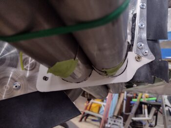
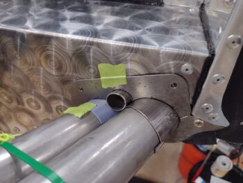
Here we have the second and last top right exhaust pipe bracket plasma cut out of 316 stainless steel.

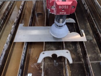
And the same for the lower right exhaust pipe bracket.

As I said, it was quite late at this point so I quickly dried off the brackets and will de-dross them, clean them up and drill out the holes tomorrow.  Then work the final fit for each of them.

Pressing forward!

Chapter 23 – Right exhaust brackets

I continued on with dialing in the right side exhaust pipe cardboard mockup brackets after having moved the exhaust pipes as far inboard as they could physically move… again, about 1/8″ from where they were.  Is this worth all the trouble?  I’m not sure, but I did/do want these pipes as balanced and symmetrical as possible with the the left side pipes (the right side still about 1/2″ further outboard than the left side).

I will say that it’s pretty much starting out from square 0 when I rewicker any position on any part of these brackets.  I would equate it to being on a 6-way seesaw with different sized kids and trying to get them all to stop and balance at the same height.  Because of the slight variance in pipe heights, matching the sloping angle of the aft baffle, and of course the angles of the pipes themselves, even knocking off an offending 0.015″ high x 1/4″ wide “bump” on the inboard pipe side of the bracket can shift the configuration to then cause a significant, say 0.030″, gap where none existed previously around the outboard pipe.  At times it really seems like a lesson in futility!

Thus the myriad of iterative cycles to dial in these brackets.  Or I am really just that bad at all this?! haha

With my cardboard templates dialed in to a good point, I scanned them into Fusion 360, created a third version model of these right side brackets, and then plasma cut them out of scrap steel.

I had an issue with my top right exhaust pipe bracket in CAD from me scanning in the cardboard bracket where it was showing up as a mirror image of my bracket (a lesson learned now), and only allowing me to cut it that way.  For test-fitting purposes I pressed forward and plasma cut this reverse 2D model, but then wasted a good hour fixing the mirror image issue for when I cut it in 316 stainless steel.

Regardless, here’s the result BEFORE I removed any dross, but AFTER I knocked the majority of rust off the surfaces (a major point here being that my plasma cutting table feeds-and-speeds are proving to be very good).

As crazy as it sounds, I then spent over 3 hours very slowly dialing in the top and bottom right side exhaust pipe brackets.  Here we have the top bracket.  From the center moving outboard the bracket needs very minor tweaks.  However, the left inboard side of this bracket needs to get shifted outboard about 0.025″, so I will transfer this to cardboard, finalize configuration, rescan, remodel, recut and confirm tomorrow.

And here we have the bottom bracket.  From these angles it looks pretty good, but there are unacceptable gaps between the pipe sleeves and bracket circular cutouts, both on the outboard sides.  This makes sense due the fact that the bracket was tacking inboard when I was first test-fitting it… again, way too easy to overshoot (per all the angles, etc. mentioned above) as material is removed to make the bracket fit into place.

Am I getting burnt out on dealing with these darn brackets?  Yes, somewhat.  But the good news is that I am clearly close to having the right set of exhaust pipe brackets dialed in and ready to be welded and mounted.  Moreover, in full disclosure I should note that I spent nearly 3 hours watching videos and re-reading my notes to reacquaint myself with both my TIG welder and the TIG welding process… all in prep, as it’s been a good while since I’ve done any welding!

Chapter 23 – Left exhaust brackets

Yep, I spent way too long today dialing in the left side exhaust pipe brackets and sleeves in prep for welding.

With the brackets and sleeves dialed in, the final configuration has the left inboard pipe ending up about 1/8″ further inboard than I had planned.  While this actually results in both left exhaust pipes being more parallel to each other than what I had planned on, it does place the inboard pipe about 3/16″ total closer to the prop spinner lampshade flow guide.

That being said, I’d be more concerned with the inboard exhaust pipe being positioned closer to the prop spinner lampshade if it wasn’t for the fact that with the curved pipe end it STILL points outboard in its current untrimmed state.  Thus my plan is to trim the pipe end to have it —and all the other exhaust pipes— to simply point as straight as possible aft, out of the cowling [in an attempt to attain Mike Melvill’s configuration of having the pipes aimed more towards the prop hub… where the prop doesn’t generate hardly any power].

I confirmed the left exhaust pipes near-final configuration by mounting the prop spinner lampshade and the bottom cowling. However, with the left inboard pipe even a bit more inboard, it made me no-kidding push the right exhaust pipe pair as inboard as possible in an attempt to balance out the left and right exhaust pipe pairs in relation to the prop spinner lampshade.  The bottom line was I was able to squeeze them inboard another 1/8″ (I’m at max inboard now).

This of course blew my current right brackets’ configuration out of the water and requires me to make new ones.  Oh well… need to get it all as correct as possible.

Below is cardboard template #4 that I slowly dialed in.  I worked until late into the evening before calling it a night.

Tomorrow my main push will be to get the third version of the right brackets dialed in and recut out of 316 stainless steel on the plasma cutter.  Also, as I did on the left side I’ll be adding in screw mounting reinforcement brackets on the aft right baffle wall to buttress up these assemblies as best possible.  Then on to welding (at least tacking) these brackets up!

Pushing forward… slow and steady.

Chapter 23 – Exhaust bracket brackets

Today was all about the left set of exhaust pipe brackets.

I started out by cutting the outboard lower sleeve after determining its configuration.

In assessing the fit of the pair of exhaust pipes in the brackets, I determined that the inboard edge of the aluminum baffle where it’s close to the inboard pipe needed trimming for clearance.  I have expected this might be the case for some time, but wanted to verify before I started chopping more stuff out.

I had to remove the exhaust pipes to allow trimming of the aluminum baffle, so at this point was the time to do some more unsexy, mundane work of creating reinforcement plates for the pair of inboard screws, and also the upper outboard screw hardpoint.

After a decent bit of assessment and seeing what material I had on hand, I landed on using 1/16″ thick 6061 aluminum angle.  Here it is after I’ve cut and shaped it using both the band saw and Dremel tool.

I also drilled a 3/32″ hole at each screw attach point through both the baffle plate and the reinforcement angle to determine and secure alignment with clecos.

Here’s a shot from the inside (forward→aft, pic 1) and after I’ve peppered the perimeter with holes for securing it with rivets (pic 2).

Here we have the left exhaust pipe inboard reinforcement screw mounting plate riveted into place.

I then did a bit of scrounging to come up with another 1/16″ thick piece of aluminum, this one is 2024, to press into service for reinforcement of the left exhaust pipe bracket top outboard screw position.

After shaping it, I then secured it in position, drilled two 3/32″ holes and secured it with clecos.  Again, this is from the inside looking aft.

Here we have the left exhaust pipe bracket top outboard screw reinforcement plate cleco’d into position.

I then riveted the left exhaust pipe bracket top outboard screw reinforcement plate into position.

Yeah, not the most exciting stuff here… but definitely required.

Not surprisingly, there is a decent little bit of tweaking to get the left exhaust pipes nestled into their final positions with the brackets and sleeves, which I’ll work on tomorrow.  I plan on knocking out the left exhaust pipes before moving onto the right side.

Chapter 18/23 – Bracket cut, cleanup

To start off, here is a shot of the 2 canopy SC-1 safety catches that I plasma cut yesterday, taking the opportunity to do so while my plasma cutting table was in “stainless steel cutting mode.”   Again, the top SC-1 was cut pretty much to the plans dimensions while the bottom one is oversized for me to cut out on the milling machine.

Here we have the majority of today’s work all in one pic.  I removed all the plasma cutting dross from the edges of the exhaust pipe brackets and the canopy SC-1s, as well as removed all the part edge discoloring with a good soak in white vinegar and then a vigorous wipe-down with 320 grit and then 1000 grit wet sandpaper.  After the brackets get welded to the sleeves there will of course be some final cleaning and buffing of the parts.

Speaking of sleeves… I then used one of my 3D printed sleeves to make a template for the top side of the left exhaust pipes.  I then cut out the sleeves from the 316 stainless steel tube and curved them a hair more in the vise to fit these 1.75″ diameter pipes.

These sleeves are just cut, so some fine tuning will occur before I weld them up to the bracket plate.  But here’s a general idea of how they will look once installed.

I’ll further note that my initial length for these sleeves is around 3″, and I can of course trim them down as configuration and weight dictates.

Tomorrow I’ll remove the bottom cowling and finish cutting the remaining sleeves for all the exhaust pipe brackets.  After that, I’ll start prepping for welding these brackets up.

Chapter 3/23 – Plasma table updates

This post covers the past 3 days.

Before I start telling my tale of woe and then subsequent victory, I wanted to grab a modern art shot of the myriad of test-fitting mockups I made to get these exhaust pipe brackets dialed in.  A good number of the repeats was when I moved the exhaust pipe positions and had to restart the bracket configurations.  Yes, in short, inputting a shape into CAD to make for both a successful cut and repeatable part is rarely the most efficient process… at least in the beginning!

Speaking of successful cuts…  a couple evenings ago I assessed that everything was a go on 3 of the 4 exhaust pipe brackets.  I had the upper left bracket mockup printing out on the 3D printer to check a final few tweaks, and I was ready to start plasma cutting the 3 other brackets out my piece of 0.036″ thick 316 stainless steel.

Alas, despite all my previous successful cuts on mild steel, my plasma cutting system apparently sensed the change and refused to cut the new stainless steel material… hmmm? (I’m compiling a video on the making of the exhaust pipe brackets, so you’ll be able to see the footage of this fail in that).

My failed cut led to 2 days of tasks to ensure my plasma cutting table, cutter and processes were all up to snuff, including updating my Langmuir Systems Crossfire Pro FireControl software as well as the Torch Height Control system firmware .  I also found a modified Post Processor for Fusion 360 —that was placed on the forum by a fellow Crossfire Pro user— that allows the plasma cutting system to simply pierce the center of each hole to mark it for drilling later rather than attempting to plasma cut it out (which can be a bit messy at times).

Moreover, since it’s been nearly 4 years since I’ve actively used this plasma cutting table, I found some “feeds and speeds” data on the forum from some fellow PrimeWeld Cut60 plasma cutter users where they had confirmed cutting amperages, torch travel speeds, air PSIs, etc. for mild steel, stainless steel and aluminum.  This was a virtual goldmine of information, although it still took nearly 4 hours for me to cobble it together into one usable chart.

I also rediscovered that there is a somewhat esoteric issue with this system between the control box and any connected computer involving the computer ground.  If the computer has a 3-pronged electrical plug, which my laptop does, than that ground spade can cause issues during the cut.  In short, I modified my plasma cutting operations sequence to now ensure I unplug the laptop prior to initiating a cut.

In related news, you may have noted in these pics that there is a shroud around the base of the plasma torch.  This shroud both keeps the sparks corralled and, more importantly, greatly limits water from splashing up on the Z-axis torch carriage assembly and X-axis crossbar.  I noted the shroud during my research where a user was using a modified silicone rubber funnel for his shroud.  For my shroud I simply drew it up in Fusion 360 and 3D printed it out in stunning <wink> gray ABS.

With all these updates, mods and test plasma cuts under my belt, I then finally got to plasma cutting the exhaust pipe brackets out of 0.036″ thick 316 stainless steel.  Here we have the upper left bracket getting cut (again, these will be shown in the video).

And a look at the upper left exhaust pipe bracket successfully cut out of the 316 stainless steel plate.

I then plasma cut the lower right exhaust pipe bracket and confirmed it was good.

And then the lower left exhaust pipe bracket…

And finally the upper right exhaust pipe bracket.  All cuts were successful, even with my tweaking the cutting speeds a bit on each round (120 ipm, then 130 ipm, and ending with 135 ipm).

If you look at the water in the plasma cutting table you can see reflections of trees since I had the shop doors open.  Stainless steel gives off some nasty gasses when it’s being plasma cut (grinded, welded, cut, etc…), thus the open doors and a fan blowing the gasses out.

Since I was set up for cutting stainless steel, I took the opportunity to recut the SC-1 canopy safety catch out the plans specified 0.020″ thick 301 stainless steel, versus the thinner stuff I had on hand and used when I originally cut it back in September 2020.  I actually cut one to the plans dimensions directly, and then another one with all the edges bumped out by 0.15″ to allow me to create it on the milling machine —for a nicer appearance (pics forthcoming… this will be a test to not only appease my curiosity, but provide a spare SC-1).

Jess invited me over for one of her wonderful homecooked meals at her house, so I closed up shop a little early tonight to go celebrate my successful plasma cuts with her.  Tomorrow I’ll clean up these brackets and press forward.

Chapter 23 – Bracket plasma cutting

The last couple of days have been a myriad of checking and fine-tuning my 3D printed exhaust pipe bracket mockups, then reprinting those until they were dialed in enough to then plasma cut out of scrap steel.

This effort of course devolved into me organizing the scrap metal area and de-rusting a number of good steel stock that’s been on the shelf for years now in this shop.

Moreover, to use the plasma cutting table I need to feed compressed air to the plasma cutter, and after some assessment and troubleshooting I confirmed that the pressure switch is TU on my shop compressor.  That took another good hour in researching potential sources of supply and prices before pulling the trigger on a still higher rated suitable substitute but at half the cost of original part numbered pressure switch.

As has been my MO this past week or so this blog post covers a couple of days, with the evening of day 1 culminating in the first 2 plasma cutting sessions being quite successful!

Here we have the bottom right exhaust pipe bracket getting plasma cut out of a piece of rusty steel scrap… mainly because I was curious how well it would work on rusty steel!

After removing the bits of dross on the backside of the cut, it only took a few minutes soaking the steel bracket in white vinegar before knocking off the rust with steel wool before it looked presentable and ready to be test mounted, which I did.  I then spent a good 20 minutes fine tuning its fit with my Dremel tool.

And the same story for the top right exhaust pipe steel test fit bracket, cut on the plasma cutting table, cleaned up and then set into place… this is after a number of rounds of dialing it in with the Dremel tool as well.

On day 2, after getting the tweaks from the right side incorporated and another round of test-print mockups 3D printed, I turned my focus onto the left side exhaust pipe brackets, first with a number of rounds of 3D printed test fit mockups, and then finally the scrap steel test brackets.

Here I’m re-cutting the top right exhaust pipe scrap steel test fit bracket.

And round 2 on the bottom right exhaust pipe scrap steel test fit bracket as well.

Here we have the first round for the top left exhaust pipe scrap steel test fit bracket.

And round one on the bottom left one as well.

Finally, here’s the 3D printed test fit bracket mockups as well as the scrap steel test fit bracket for both the left and right sides.  I had a couple of phone calls I needed to take, so that blew my evening’s schedule a bit… it was getting late and I need to clean the dross off the backside of these steel plasma cut brackets before trying out their fit on the engine, which I’ll do tomorrow.

Slowly walking it in . . .

Chapter 23 – Exhaust bracket mockups

Yes, it’s been an admittedly slow, iterative process slogging through the minute tweaks to dial in the top and bottom exhaust pipe brackets to get them to acceptable tolerances before cutting them out on the plasma cutting table (at least that’s the plan).

Here is the “final” (always with caveats and alibis) lower right exhaust pipe bracket mockup, hot off the 3D printer press.

And with it test-fitted in place… Version #7 that is.

I also continued on with my tweaking of the top right exhaust bracket as well, dialing in and eliminating (or mitigating?) the gaps between the bracket and the half-tube pipe sleeves and the center crankcase vent pass-thru tube.  Here we have Version #9 (pic 1) and Version #11 shown (pic 2).  As I write this post the latest version is #12.

I’ve also been spending my time on getting the left side exhaust pipe brackets dialed in as well.  Here I’m about round 2 of my 3D printed exhaust pipe bracket mockups for the left side.  I suspect I’ll need a few more versions for both the top and bottom, respectively, before I’m ready to plasma cut these and start welding them up.

Speaking of plasma cutting… since I haven’t used my plasma cutting table in a couple of years, not surprisingly it took me well over 3 hours to get it cleared off and cleaned up in prep for software updates, ops checks and test cuts.  Then I can start making some parts!

As I closed up shop and headed into the house for the evening, I checked the mail to find that I got the PMag spark plug & ignition wire end terminals from the Emag Air bubbas… here those are.  I need to check if I have a spark plug wire crimper on hand from my old chopper building days.  If not, I’ll have to acquisition one of those.

I’ll be spending most of the day tomorrow (Sunday) with Jess down in Wilmington, so no physical (just mental!) airplane building occurring.  I suspect Monday will be final tweaks on the exhaust pipe brackets and working to finalize bringing the plasma cutting table back online.  I plan to plasma cut the top and bottom exhaust pipe bracket plates on Tuesday and get them drilled and tack welded up.

Chapter 23 – Exhaust pipe re-welded

Today was all about “engineering” and design tradeoffs and task redo’s.

I started off with lopping off an angled piece of 3/4″ stainless steel tubing that will serve as the right exhaust pipe bracket’s pass-thru for the crankcase vent tube —that nestles into the top V-groove of the right exhaust pipe pair for about the aft 2/3rds of the overall exhaust pipes’ run.  Since the pipes angle inboard the hole in the bracket plate needs to be less round (pic #1) and a bit more oval (pic #2).

After messing around with the right exhaust pipe bracket crankcase vent tube pass-thru for a bit, rewickering the CAD model and 3D-printing updated versions, I then took a break to go see my race car header welding buddy James to (re)weld up the left outboard exhaust pipe.

James did a phenomenal job as par usual, and below is the freshly rewelded left outboard exhaust pipe back home and in its place on the engine.

Now, that being said: my goal was to position the curved exhaust pipe insert (new piece) to get the outboard exhaust pipe “around the bend” in regard to doglegging it around the vertical slip tube portion of the inboard pipe, to then nestle in and align parallel with the inboard exhaust pipe on the back end.  Unless tack welding these joints and course correcting in situ on the engine, it’s not unreasonable to expect a slight loss in translation when I position it by pressing and taping together in my shop, compared to it actually getting welded up on a bench 40 miles away.

On the left exhaust pipe pair I have a gap between the pipes that is present (no issue as per Klaus Savier… actually preferred!), and after its rewelding the outboard pipe’s curve is probably 0.15″ to 0.19″ (a few degrees) more than I had planned.  This pushes the outboard pipe’s middle out away from the inboard pipe’s vertical slip tube portion a bit more when the very aft ends of the left pipes are kissing.  Thus, to keep the gap line between them more parallel, I need to kick the inboard pipe even more inboard about 1/4″, perhaps even as much as 3/8″ by the end of the day.

Bear with me…. as I told my buddy Dave Berenholtz in an email recently, these pipes are simply not the right ones for my engine and cowlings.  And with that being said, the final curve on the very aft end for all 4 pipes is at about the worst possible position, driving me to cut the pipes’ ends much deeper into the cowling (2-2.5″) than I prefer.

Or so I thought.

The slight unintended kick-out on the just rewelded outboard left exhaust pipe may be a blessing in disguise (in keeping with my motto: “better to be lucky than good!”) in that by bringing in the pipes as inboard as possible —”uncomfortably close” to the prop spinner lampshade— it then better aligns the outboard turning final pipe bend to shoot straighter out the back.  Versus trying to cut off the majority of each aft/final bend and point the straighter pipes inboard.  Roll with the flow and use your opponent’s natural energy against them. 

I looked back at my notes on when I was configuring the top and bottom cowlings in joining them together around the aft cowl opening.  My distance from inboard edge of the left inboard pipe to prop spinner lampshade was 2″.  That distance on the right was 2.5″.  Currently I’m pushing those respective numbers inboard about 1/8″.  Now, that measurement is not the opening exit point of those inboard exhaust pipes, but rather the closest point of the pipe that then curves back outboard with the exhaust exiting either parallel with aircraft centerline (at best), but in reality actually aimed a tad more outboards.

To capture and verify what I had assessed on the left side, I mounted the top cowling in place.  I also wanted to look at the upward angle of all the pipes to see how close the exhaust would get to the actual aft lip of the upper cowling.  Close, but no issue.

Now, the right exhaust pipes are not trimmed at all, so they appear much more outboard in pics than they really are.  I’ll reiterate that without cutting and rewelding, the closest these pipes can come inboard is about 2.35″ away from the lamp shade.  I however was still at 2.5″ away and since I’m bringing the left set of pipes further inboard (and trimming the ends to be about 1.5″ inside the cowling), I needed to bite the bullet and get the right side pipes as inboard as possible as well.

Which of course jacks up all the work I just did on the right side exhaust pipe brackets.  Do it right! (right?!)

Using my known new gaps by driving the right pair of exhaust pipes further inboard by about 1/8″, I then redrew the bottom right exhaust pipe bracket onto cardboard.  Not bad just out of the gate I have to say, and definitely good enough to import into CAD.

I then did the same thing on the top right exhaust pipe bracket.  Again, not too bad at all.

I took my latest top and bottom cardboard mockups of the right side exhaust pipe brackets into the house and imported them both into Fusion 360 CAD and got the initial modeling of those knocked out.  I 3D printed the top bracket mockup and did a quick fit test on it out in the shop.

It was very late in the evening by this point, and with corrective annotations in hand I took the top 3D printed mockup back into the house to tweak it further tomorrow.

Chapter 23 – Exhaust pipe bracket start

I started off today by mounting the bottom cowling to see how my just-installed aft bottom baffle seals fit into the scheme of things.  They look good and functional, so I’m pressing onward, upward and forward!

I spent about 45 minutes going through another few versions of cardboard mockups for the lower right exhaust bracket before dialing the last one in that was good enough to import into Fusion 360 CAD.  After modeling it up I 3D printed a 0.020″ thick version and checked it out in situ.

It’s hard to show all the nuanced gaps and seams that need to be tightened up in pictures, and of course there’s the invariable relational and unintended consequences thing where making one mod negatively affects a different area of the part.  That being said, here is Version 1 that kicked off this very iterative process.

Besides trying to get the seams around the pipe sleeves as air tight as possible, my initial main concern was the “water level” of the bracket itself in that I want it to be very close to covering half the exhaust pipe, lest I get more than a half moon and the installation and removal of the bracket around the pipe would be difficult, if not impossible.  Also, the right outboard “bird beak” needed dialing in, as well as both screw hole positions.

I have a specific position on the lower left where I want the platenut to get mounted, thus the hunting and pecking with each version to get the inboard screw hole positioned correctly.  I still had more finetuning on the curves around the sleeves, and of course more dialing in the “bird beak” on the right.

Version 4 is very, very close to the final configuration I need.  Any more fine tuning at this level will simply be with a file after I plasma cut this bracket half out.  The seams are certainly close enough with the seams that very little extra filler rod material will be required to fill any gaps.  I’m calling this one good!

As a point of interest, here is all the versions of the lower right exhaust bracket in their reverse progression from top to bottom.  These each took about 12-14 minutes each to print, but also required a good 20 minute cool down before removing them from the print plate.  I’d say each one, including the markup and CAD work represents at least one hour each.

It was getting a bit late, but I wanted to get a few rounds of the top right exhaust pipe bracket under my belt before calling it a night.

Here I’m on version 2 (or 3?) of the cardboard bracket mockup (pic #1) before getting one good enough to import into CAD.  I then got the basic outline modeled up and 3D printed a plastic mockup (pic #2).

I essentially worked on filling the same gaps and problem areas on versions 2 and 3, I simply wasn’t aggressive enough on my gap fills on version 2 as required.  I also played around with the top inboard and outboard corner radiuses a bit too.

Here we have the final version (#4) for the night.  I actually kicked off the print and intended to check it in the morning, but curiosity got the best of me and I snuck back out to the shop to see how she fit.  As you can see, I added the mounting screw holes in each corner for this version.

I then marked around the perimeter of this bracket mockup and each of the mounting screw holes to ensure that there was enough meat behind it to mount plantenuts, and to also ensure that the bracket would cover the gap around the exhaust pipes. Looking good so far!

Tomorrow I’ll see how far I can get in constructing this right side bracket… if possible and the plasma cutting goes smoothly, I’ll try to get this tacked up to have James weld this sucker up along with the left outboard pipe.  A long shot, but I’ll try.  We’ll see.