Chapter 22 – G7 Ground Buss

Another 2-day post here… where I finally got the E-Bus inventoried, fuse values adjusted (as per respective component manuals), some items moved, and some items removed.  Let me tell you, the E-Bus was a heck of a lot busier to finalize than the Master Bus was any day.

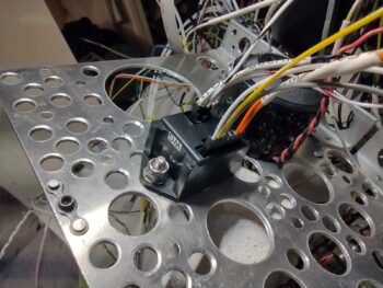
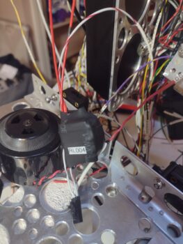
I also finally got around to wiring up one of my last (but not THE last of course <wink>) relays on this bird: Relay #4 (RL004).  This relay simply keeps the power off for the Canopy/Gear Warning System (see that big ‘ol piezo buzzer in the pic??) until the engine is started.  Then all the lights can start flashing and the horn can start blaring that the canopy is open . . . etc.
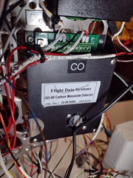
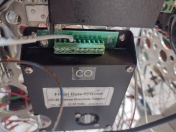
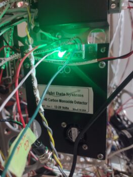
I also spent a good bit of time really digging into the GD-40 CO Detector manual. At the end of the manual it states that these things have a life of about 5-7 years, although often make it to 10 years before the sensor has to be renewed and calibrated (yes, question is: Is that shelf life or operating life?).  Apparently (as I don’t remember!) this thing ships with a combined green/red LED that is used to run self-tests and display any major issues with the unit.

I wanted to run these tests in case I needed to ship the detector back to the manufacturer for a refresh before I start flying.  But speaking of flying, this thing passed all the self-tests with flying colors… literally, as in this steady green light during normal ops means that there is/are no issues.  Rock ‘n roll!
Day 2, after about a good final hour on the E-Bus, I got busy doing the final build on the G7 Ground Bus.  I made my final tweaks in CAD and kicked off the 1 hour 45 minute 3D print for the mounting bracket.

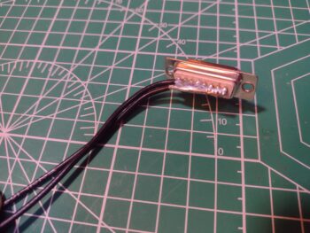
I then went out to the shop to grab some 14 AWG wire, cut two lengths of it, and then proceeded to solder those wires to the aft side of the female DB15 D-Sub connector.  After the solder cooled, I did a continuity check on every socket with each wire lead. All good!
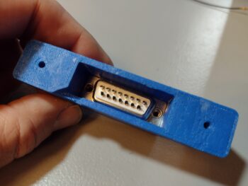
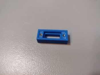
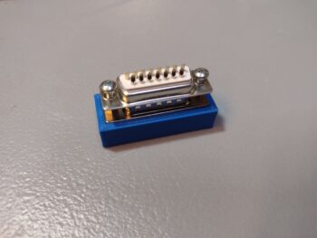
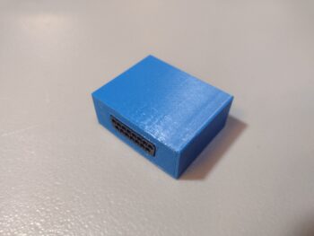
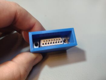
Once the G7 ground bus mounting bracket was through printing, I cleaned it up and hot-sank threaded brass 4-40 inserts into the inside face.  This allowed me to install the male DB15 connector first, with the wire-soldered female DB15 after that, and secure them both as a pair with 4-40 screws.

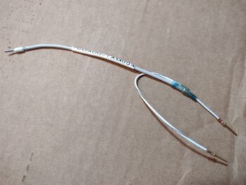
As you can see, I then labeled the wire pair and crimped a ring terminal for connecting it to the G4 main ground bus.

Now, the 4-40 threaded inserts worked very well, but the holes on the outside —where I intended to hot sink 6-32 threaded inserts— were a bit too narrow in diameter and the resulting excess plastic really gummed things up.  I tried to gingerly use a 6-32 tap to clean things up, but it grabbed the threaded inserts too tightly and broke them loose from the plastic holes… so I just pulled them out.

I then re-tapped the plastic holes and rounded up some washers and Nylock nuts.  However, I had to go down to the Lowe’s Aviation Department to pick up some 1″ long SS screws to get this thing to final install.

The threaded insert issue notwithstanding, I’m very happy with how the install went.  In fact, I like this method of installation better since the washers and nuts provide an even more secure mounting.
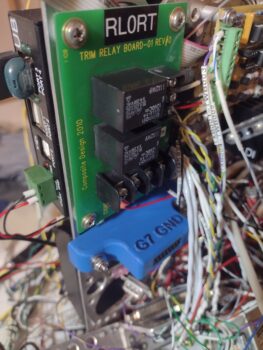
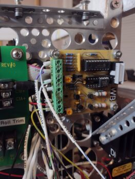
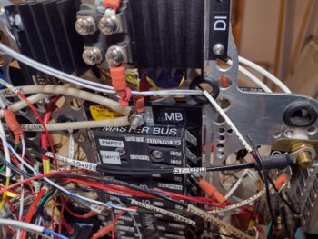
Here we have the double-wires going to the G4 main ground bus on the Tri-Paragon (and no, STILL have not gotten to cable management… yet!)
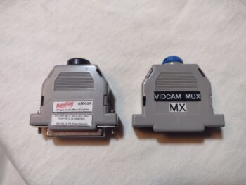
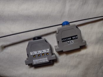
I also spent another 5 minutes in CAD finalizing a small dust cap that gets clamped into place between the two back shell halves on the Video Camera Mux, that the 4 individual video cameras plug into.  My other twin sister unit of this style of small-footprint electrical device is the 10-channel Audio Mixer, that I put in each pic.  The black dust cap on the audio mixer is where I got the idea to fill that hole in the backshell case of the VidCam Mux.

Note that I added a slot for a zip tie in my 3D printed dust cap just in case I want to use that to help secure it onto the Tri-Paragon (pic 2).
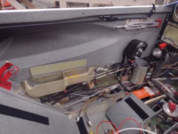
The weather was finally a tad bit warmer today (mid-50s) and in prep for installing the Tri-Paragon in the bird (planning to start tomorrow) I installed a couple of wires, labeled a few more, did a thorough scrubbing of the quite-dirty P4 connector (both sides), and then removed the left armrest to expose the handful of micro-switches on the throttle quadrant that will need wired up.
Back in the house I did some more exciting administrivia for about an hour, in part cleaning up the numbering of my panel top row indicator lights that I’ve been playing musical chairs with the past few weeks.  I also had to evaluate and draw up a new circuit diagram to add those lights into the current wiring schema.

Yes, hoping tomorrow proves to be a significant milestone with the Tri-Paragon actually mounted inside the airplane!

Chapter 22 – Getting very close!

… to getting the Tri-Paragon mounted into the bird!

This post covers the past couple of days, where on Saturday I received the 0.5 amp ATO blade fuses from DigiKey.  These are an answer to a question I had for Rich on the AG6s, since I had the AG6s both wired together at one fuse position on the E-Bus through a 1 amp fuse. The install manual states to use a 1/4 amp fuse, and I figured a 1 amp fuse would be ok for two units combined, but wanted to check.

Well, as somewhat par usual for this build, Rich stressed that I really should follow that instruction as closely as possible.  Thus my push to order 0.5 amp fuses to use for the pair of these AG6 units (needing only one of course, but another 2 for spares).

Now, I cold have gone with a glass 0.5 amp fuse, but I didn’t want to rewire the AG6 power leads and renumber the wires and E-Bus fuse block.  I’ve had enough of that stuff and prefer to avoid the time and effort if at all possible.

I compared these 0.5 amp ATO fuses with the ATC fuses and noted right off the bat a significant size difference, albeit mainly in height.  To be clear, you can find a lot of ATC/ATO fuse products, and having never (knowingly) worked with ATO fuses before, I thought the differences were a bit more minor.

Here I grabbed the first shot to show that the 0.5 amp ATO fuse was NOT fitting into the BUSS brand fuse blocks I have on hand… thus pic #2 to show that the label specifically denotes this as a “ATC FUSE PANEL”.

Here is one of those dual ATC/ATO products I mentioned, where either ATO or ATC fuse fits into this inline fuse holder.

After pondering my options, and considering going the inline fuse route off the E-Bus fuse panel’s threaded connecting stud, I wanted to first try a little experiment with one of the three 0.5 amp ATO fuses I bought.

First, I used my micrometer to measure and annotate the width, length, etc. of the ATO vs the ATC fuses.  Then, using a razor knife and Dremel I trimmed down the plastic a bit on all 4 sides.  Here we have the trimmed ATO fuse on the left, and standard unmodified one on the right.

Of course I didn’t want to take too much material off, where the ATO fuse wouldn’t fit tightly, so I took my time in this iterative process to ensure the ATO fuse fit snugly with the plastic and not by just relying on the metal blades (although admittedly that’s where the majority of the clamp force is, I highly suspect).

And here we have it… Voila!  The whittled down 0.5 amp ATO fuse fits in my ATC Buss fuse block.

And here it is installed in its actual position on the E-Bus.

Speaking of busses, I did a thorough review of every position on the Main Buss, getting into the manual for each connected device and component, verifying that the components ID’d matched my diagram, and evaluating each fuse rating per each manual to ensure they were correct.

I swapped the TCW Tech Smart System off the main buss with a component on the E-Bus, since I wanted the Smart System on the E-Bus in case I ever needed to do an engine restart while on E-Bus only power (I know, rare, but potential catastrophic to not have it on the bus with power when you need it).

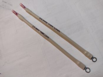
I started doing the evaluation for the E-Bus in the same manner as the Main Bus, but it was getting late and I wanted something a little less mind-numbing (and physical) to knock out before I quit for the evening, so I made up my last (ACTUAL LAST ha!) Fuse Link, this one a 20 AWG fuse link for the 16 AWG nose gear wire.

Tomorrow I’ll get back to finalizing my E-Bus review and verification, and will work on wiring up Relay #4, which is one of the last relays I have to gin up.  I’ll detail more about it when I show some pics of it tomorrow.

And, as per usual, still PUSHING FORWARD!

Chapter 22 – Taking the small wins…

I had to stop by the airport to pay my hangar lease, so I figured I would hop by the hangar to “feel my space” and brainstorm about future tasks.

While nearly the entire rest of the area is back to business after this quite heavy snow storm, apparently the airport needs some remedial training in snow removal.  Of course the bigger hangars were all cleared of snow, but us little guys still had piles of over a foot of snow just outside our hangar doors… I’ll just leave this right here.

I stopped off at the “Aviation Department” of my local True Value Hardware store to pick up some 1/2″ long 4-40 screws for my new G7 D-Sub + bracket ground bus… the new screws worked a treat!

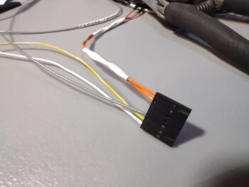
I then got busy selecting wires (white, gray and yellow) and terminating them with tiny sockets, then inserting the wires into the JB Wilco Canopy & Gear warning system’s J2 connector . . .

Yes!  Even though the darned thing is this small, it has TWO (2) connectors on it.  Of course after digging in the manual I realized the 3-socket power connector was wired backwards (yes, even I do dumb things!)… so I swapped the two end wires, since thankfully the middle wire was correct!  I was 33% correct! ha

The two wires left to terminate in the J2 connector will come from the nose gear actuator microswitches [Note the mojamma piezo buzzer behind it, which is part of this warning setup].

I then spent the next 45 minutes wiring up the GD-40 CO Detector.  Here you can see from left-to-right are the two RX-232 wires that feed the HXr warning/alarm data, the audio wire to the audio mixer, and on the far right end are ground and power.  EZ-PZ!

I’ll note that cable-management has not commenced in earnest yet on the Tri-Paragon, thus why the rats’ nest look continues at this point.

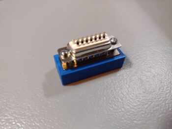
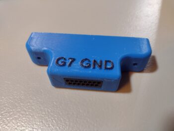
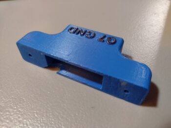
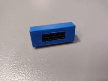
Shortly after I tested the 1/2″ 4-40 screws, I got into CAD for about 10 minutes and finished the “initial final” design of the G7 Ground Bus mounting bracket.  I threw some raised letters on it for some fun bling (pic 1) and also made an angled notch for the exit of the two thicker wires that will tie this ground bus into the main panel G4 Ground Bus (pic 2).  I then kicked off the 3D print.

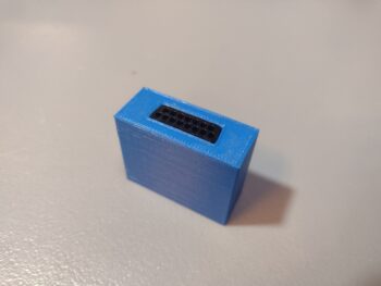
Another shot of the D-Sub face (pic 1), and the inside face of its paired male DB15 connector that will get two 12-14 ga wires soldered to all the solder points (pic 2).

I received my order from Stein Air that included a fair number of connectors, including this mini-Molex connector for the two wires exiting out of the Warning Annunciator Sub-panel for the Indicator Lights’ Push-to-Test (PTT) button circuit.  It was a fairly quick kill, so I knocked it off of my to-do list.

Here shown with the both sides of the connector terminated, wires in place.  (Yes, I have a love-hate relationship with Mini-Molex connectors… what can I say?!)

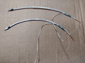
My last task of the evening was ginning up yet another 22-AWG 2-wire shielded cable with ground pigtail for the Dynon Intercom to Trig TY-91 COM2 radio connection.  While there will be a BUNCH of work to finalize the intercom install, this completes the wiring out required before the intercom wiring (attached to the Tri-Paragon) is linked up with what is currently in the aircraft.

Here’s a shot of that COM2 cable (lower left to upper right of pic) installed into the Dynon Intercom D-Sub connector.

Notice I didn’t mention any wiring labels: as I’m in an exponential downward curve of needing those (at least for now) as I applied those fairly heavily during my initial forays into the Tri-Paragon… now I’ve had the same single lone label waiting on the “to-be-printed” list for over a day for some new additions (I normally print in batches of 6-7 to maximize the heat shrink material in the cartridges).

Finally, I’ll note that I had some good comms with both Eric Page re. the video cameras’ wiring and Rich on some issues I need to clear up on the AG6s.

Rockin’ and Rollin’!

Chapter 22 – Electrons vs labels

This post covers a smidgen of my efforts over the last couple of days.  My overall goal at this point is to get the Tri-Paragon as prepped and pre-wired as possible before it gets mounted into the plane.

Besides cleaning it and blowing out all the nooks and crannies with compressed air, I realized that I was a bit premature in mounting the relay deck plate onto the top shelf, given that I just didn’t have the access to get in to wire up the AG6s, etc. so off with the top shelf and associated components.

I’m pretty much going through every component, connector and wire to again ensure that the Tri-Paragon is as prepped, clean and optimized as possible to get mounted into the bird.  Lord knows there’s an insane amount of wires hanging off this thing, and then add that to the insane amount of wires currently inside the bird?!  I need to be focused on connecting everything up, not fixing or redoing something that I could have caught on the bench.

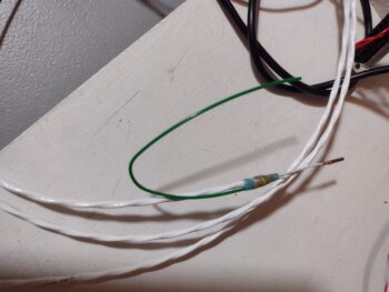
One thing I did was I went through all the wiring diagrams and inventoried the total amount and types of Fuse Links I needed.  The final tally was two 22 AWG fuse links: one off the Master Bus connecting stud for the ALT FLD (B&C voltage regulator) circuit breaker lead and the other off the E-Bus connecting stud for the P-Mag circuit breaker.

With my alarm inputs paired down to 5 per AG6 to allow me an audio alarm out to the audio mixer, I worked up those two single-wire shielded cables and finalized those connections.

I also took a few moments here and there to work on my new G7 ground bus, where I did a quick measuring of the screw holes in the 15-pin D-Sub connector and transferred those over to the mounting bracket CAD model.  I then 3D printed out this test top section of the mounting bracket and used a special-tipped soldering iron to heat sink some 4-40 brass threaded inserts into the plastic (common practice in the 3D printing world).

I then test fit the male and female DB15 connectors into the bracket top test piece and secured them with screws into the brass inserts.  Yes, these are 3/4″ long screws, so I’ll need to pick up some 1/2″ long to finalize the assembly of this.

Here’s the front/top view after the screws were threaded in place.

After my G7 ground bus mounting bracket shenanigans, I got back to work on the seemingly endless amount of wires, connectors and components on the Tri-Paragon. I have both AG6s wired for power, ground, dimmer and audio, with 3 of the 5 inputs wired up on the right side AG6-B.  The other input wires are physically in the aircraft.

I only have 1 of the 5 inputs on the left side AG6-A wired up, so I didn’t feel inspired to grab a pic of that (note the Roll Trim relay board on the left side of pic above: that will get wired up once the Tri-Paragon is mounted in the plane).

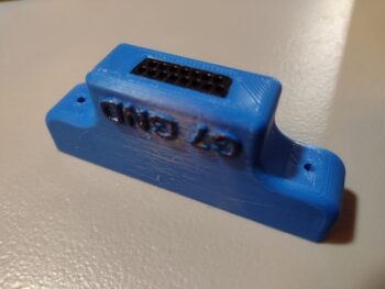
After a few more hours working on the Tri-Paragon, including at least 15 new wire labels applied, I spent about 5 minutes in CAD to increase the height of the G7 ground bus mounting bracket body, and then kicked off the 45 minute print.

Here is the result of that…

And shots with the DB15 D-Sub connectors in place:

A good bit of what I am doing is simply verifying that the current configuration is, in fact, current so that the physical component installs, wiring and labeling all match… after all these years and countless modifications, changes and updates.  I’ll provide two quick examples to emphasize what I’m discussing:

Case #1:  On the wires exiting relay #9 —which controls the switching of PTT, headphones, etc. between COM1 and COM2— I had two wires labeled with masking tape: one “COM 2 PTT Pin 7” and the other “COM 2 Pin 14.”  There is only one glaring issue with these labels, neither of those pins are required on the Trig TY-91 com radio.

Perhaps I got them confused with the GNS-480?  Which I had originally designated as COM2… but it has multiple connectors (aka “plugs”) on it that are all preceded by “P” as in P1, P5, etc.  So it wasn’t that.  I then looked up my old wiring diagrams on my computer… nothing.

Clearly these wires didn’t match my current wiring diagram.  After pondering for a bit, I remembered I had considered using the MicroAir M760-REM as my COM2 radio.  After finding the manual on the GRT website under “Legacy Docs” I found the culprits.  I was then able to finalize the conversion (8-10 years later?) from the way old COM2 radio connections to the “new” Trig COM2 radio.

Case #2: I also focused on wiring up the dimmer (1 of 2) connector that is used by the AG6s, TruTrak ADI, etc.  While working in the rats nest of wires on the right side of the Tri-Paragon, where the dimmer connector is located, I happened across a gray wire with a red stripe.  The label denoted it was from the HXr to be wired to the dimmer I was working on.

Excellent! Another wire terminated and off the to-do list I thought.  So I trimmed the wire to length, stripped it and was just getting ready to crimp a D-Sub pin onto it when I thought, “I better double check the connector pin-out diagram for this.”

Sure enough, no HXr dimmer connection existed on any diagram, nor on my connector pin-out page.  But it WAS clearly labeled.  So I did another 10 minutes of investigating to find that I did have this HXr dimmer connection at one point, but nixed it since I had no space and needed a pin to hook up the avionics panel ammeter located in the nose. So out that wire came to make room for the Ammeter #2 wire to get inserted (that wire is also currently in the bird patiently awaiting to be connected!).

I am really beginning to wonder if it would have been better to simply wire everything up all at the end of the build!

Speaking of wiring!  Another target for finalizing its wire connections before the Tri-Paragon is installed into the bird is the Carbon Monoxide warning sensor (Flight Data Systems GD-40).  I must say that verifying the wiring in the manual completely reinforced my decision to pull this input off the AG6.  The audio warnings out on this unit is actually quite impressive with a caution message first, then a warning message and also an all clear notification.

All the capabilities are fine and dandy, but we of course need to connect this CO Detector to the audio mixer, so yet another single-conduit shielded wire to gin up for that specific purpose.

And here is that audio wire terminated in the GD-40 CO detector.

Tomorrow I plan to finish off terminating the remaining wires as well for the GD-40 CO Detector.  I’m hoping that by the end of the day tomorrow I will be ready to no-kidding haul the Tri-Paragon out to the shop and install it into the bird.

Pressing forward… albeit slowly!

Chapter 22 – AG6s configured

Today was all about finalizing the testing and configuration of both AG6 warning annunciation units.

After my discussion with Rich, the creator of the AG6 unit, I committed to pair down each AG6 to 5 vs 6 inputs to allow me to use input #6 as an audio out connection (technically through pin 7, which negates using Input 6) to the 10-channel AMX-2A audio mixer amplifier.  Rich noted that hearing an audio warning while an alarm flashes increases your chances of noticing it exponentially.  This exact dynamic has been stated by my buddy Marco (he’s even pointed out this phenomenon in some of his avionics videos during flights in his Long-EZ) and I totally concur… thus my emphasis on adding audio.

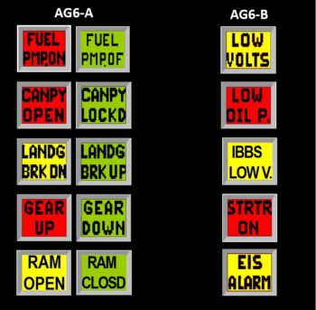
Before I get into the particulars of today’s task, here is the final (at least at this point in time) depiction of the AG6-A (aka #1) and AG6-B (aka #2) units.  Since I only had 1 of the 5 “Ok” screens for AG6-B, I simply left them off.  But as you’ll see below, they do exist.

The above depiction shows 5 alarm inputs on each AG6, versus a week ago when there was 6 per AG6.  Again, I combined (AG6-A) the 2 separate Gear UP/DOWN inputs into one to free up Input 6.  On AG6-B I deleted the “Slow Speed” Input 4 and swapped it out with the Starter ON alarm from Input 6.

That all being said, I started off on AG6-A by swapping out the previous Carbon Monoxide alarm (that also feeds into the EFIS for an onscreen warning) for the Fuel Pump ON/OFF on Input 1.

I then spent nearly 2 hours working the parameters to get all the AG6-A alarms working.  Again, I also combined the Gear UP alarm on Input 4 with the Gear DN/Locked alarm on Input 5.  If you saw my blog post from yesterday, this eliminated the non-colored “ghost screens” that I was getting.

Finally, I configured AG6-A to output warning audio on Output 7.

I then focused on AG6-B, and started testing all the alarm screens.

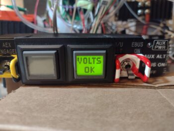
Input 1 on AG6-B is the Low Volts Alarm from the B&C voltage regulator.  I’ll note that the alarm condition for all the amber or red alarm screens flash until I press the acknowledge button (screen).

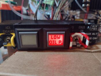
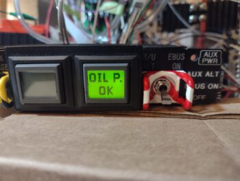
AG6-B Input 2 is the backup external oil pressure alarm (separate from the GRT EIS) that gets its signal from the Hobbs meter/backup oil pressure switch.

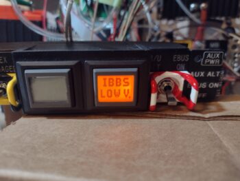
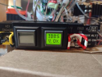
Input 3 on AG6-B is the low voltage warning light output from the IBBS.

Ok, so Input 4 was the Low Speed alarm that I swapped out for what was on Input 6, the Starter ON alarm.  The reason I pulled the plug on the Low Speed input was that originally I had it hooked up to an airspeed switch that was set at 70 knots.  But as requirements for various components hooked up to it changed, I changed the airspeed switch setting to 90 knots, so off it came from the AG6-B . . .

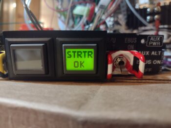
and in its place is the Starter ON alarm.  This is to monitor the starter in case it hangs up and doesn’t disengage.  As I’m sure you all know, this is a very dangerous situation in that it will fry the battery if that circuit stays open too long.  It’s the very event that burnt down Brian DeFord’s fairly new Cozy in a matter of minutes on the ramp.

On Input 5 I have the GRT Engine Information System (EIS) external alarm.  This obviously is a warning to scrutinize all the engine gauges to ensure all parameters are in spec and operating correctly.

And as with the AG6-A unit, I then programmed Output 7 on AG6-B to send the alarm-out audio to the audio mixer amplifier.

Tomorrow, with a little less snow, I plan on taking an even bigger bite out of my electrical to-do tasks to get the electrical system complete and the panel installed in this bird.

Chapter 22 – The AG6 Dance…

So my wife, Jess, and I have essentially been holed up in the house for the last 2 days as we weathered the North Easter coastal blizzard that hit ‘ol North Carolina pretty good.

Oddly enough, in talking to Marco, who is almost 4 hours north of us, they got barely a smidgen of the snow that we got.  Typically quite unusual for here, although we did a good little bit at the beginning of last year as well.

The crazy wind is what created the major varying depths of snow, with it just a few inches in some spots and over 18 inches deep in other spots.

During our time cooped up in the house, I took the time to go back through some videos on the GNS-480, HXr and Mini EFISs, as well as the Trio ProPilot autopilot to re-familiarize myself with the panel component functions… as I mentioned in my last post.  I also did some more assessment of my AG6 warning annunciator systems.

In fact, I spoke with Rich, the creator of the AG6s, for over an hour about my setup and how to tweak it to what I want it to do for me.  I need to get some info to Rich and he also needs to do some of his own deep dives in working out the solution to meet my requirements (hopefully).

Today, Day 3, I brought the Triparagon in from the shop to hook up power to AG6 #1 and test out all the input circuits.  I haven’t reprogrammed input no. 1 for changing the Carbon Monoxide (CO) meter input out on the AG6 to the fuel pump, but I did check out the functioning as it would be with the fuel pump hooked up… and it check out fine.

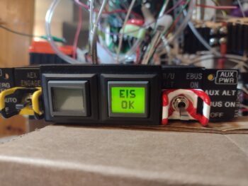
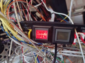
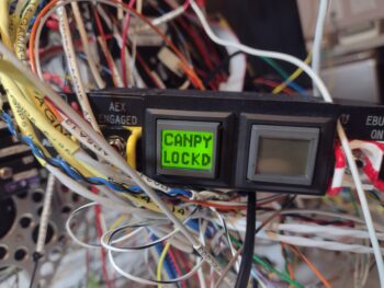
Input no. 2 is the red canopy open warning (I just finished this circuit as part of the 2-relay configuration atop the relay deck) with the green “Canopy Locked” screen lighting up once that action is complete (I’ll note that in person the black lettering on the red screens is just as dark and pronounced as they are on the green screens).

I couldn’t get either the “Landing Brake DN” and “Landing Brake UP” screens of input no. 3 to fire up, so I’ll have to work that.

You might have noted the trend from above that most single inputs have a pair of alarm, warning or “ok” screens as the outputs… except for this next pair since they are actually separate circuits:

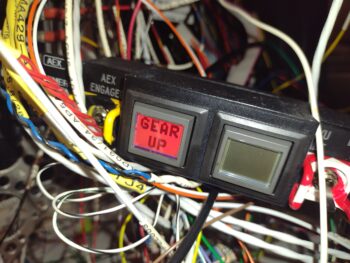
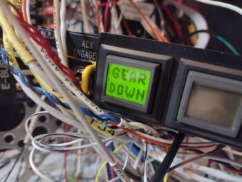
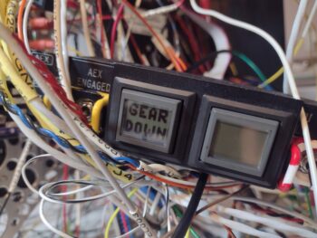
Input 4 connects to the AG6 via one of the microswitches on the throttle quadrant, so that when the throttle is closed <10% AND the gear is up, this alarm will light up (pic 1). Once the gear is down (again, a completely separate circuit), Input no. 5 lights up to verify that the gear is down (pic 2).

Now, due to the fact that these two inputs are normally a set pair on one input, I noted that I’m getting a no-color “ghost screen” flashing up from each one after I acknowledge (press the screen/button) the warning/notification.

Again, I’ll have to work with Rich to see if I can eliminate these two “ghost” screens.

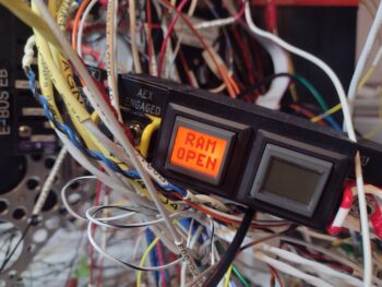
Input no. 6 is RAM Air open and is an output of Relay 19, which means it lights up if I’m below 90 kts and my RAM Air valve is still open… again, I want something motivating me to close the valve as to not subject the engine air intake to any possible FOD.

And yes, there is a green “RAM Closed” screen that indicates once I close the RAM air scoop valve, I just forgot to grab a pic of it.

Tomorrow I plan on testing out the inputs on AG6 #2, and then send off my findings to Rich so we can troubleshoot the issues I’ve discovered.

Snow be damned… I’m pressing forward!