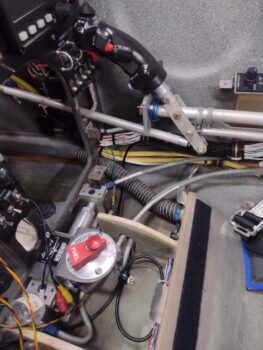
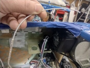
I started off today knocking out a few more power-up circuit tests with the target being the USB and cigarette lighter chargers for both the front pilot seat and the GIB. Here we have the pilot cigarette lighter charger just forward of the lower instrument panel bulkhead and just to the left of the center panel strut (pic 1). If you look closely, you can see the green light. I’ll also point out that this charger is on the battery bus so it’s always hot.
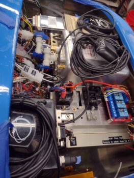
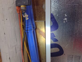
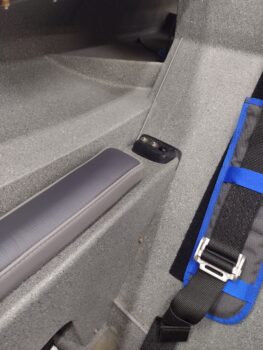
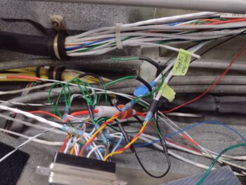
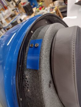
In the back seat area, left upper side just aft of the pilot seat and just below the longeron is the pair of chargers, both USB and cigarette lighter style (pic 2). Again, looking at the lights you can see these are both powered up. Moreover, with each charger I plugged in my phone to ensure that it was charging, which it did on all the chargers. These chargers connect to the Master Bus off of one fuse.
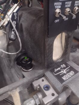
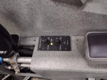
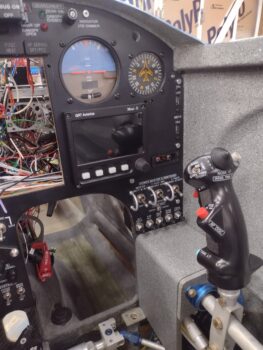
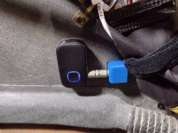
Lastly is the pilot USB charger located on the right side of the panel’s center strut. It has its own fuse off the Master Bus. Here I have it charging the Intercom Bluetooth module anytime the Master Switch is flipped on. Interestingly, there are no lights on this unit to let you know that it has power, other than charging something.
 A couple of days ago I started converting the Tri-Paragon relay deck CAD model to use its screw hole patterns to create another deck one level above the relays: a GPS puck mounting plate… I have GPS pucks coming out of my ears and I think they just may be multiplying like rabbits!
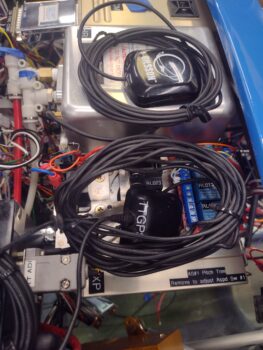
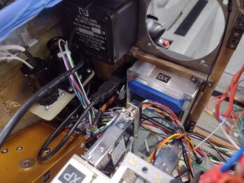
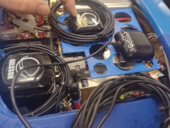
In the lower left corner is the Mini-X GPS puck mounted atop the TruTrak ADI. Yes, it’s easier cable-wise to get it sitting nicely on the ADI moreso than the ADI’s own GPS puck, which is the farthest forward (to the right) in this pic. The GPS puck at the top is the GRT AHRS, with the puck itself situated close to the inboard edge of the shelf plate with only the wrapped cable overlapping onto the AHRS (I confirmed with GRT that this is ok).
 Well, after getting the puck locations dialed in, I then removed some of the lightening holes to give both antenna pucks a solid surface to sit on. i also rounded the corners before 3D printing Version 2.
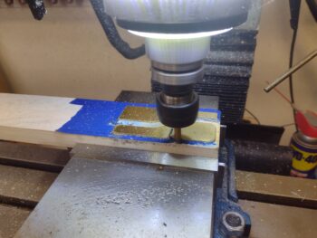
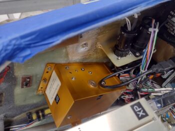
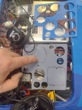 This morning I picked up some 2″ long CS brass screws and used them —after cutting some aluminum tubing for standoffs— to temporarily install the Version 2 GPS puck mounting plate. The ADI GPS puck wire bundle will get zip-ties to the outboard edge of the plate and hang down vertically below it.
Of course I have some tweaks that I’ll make over the next few days before I spit out Version 3, and then when the final version looks good I’ll cut it out of 0.035″ thick 6061 aluminum. I’ll also note that I have 2″ long CS 4-40 screws on order from McMaster-Carr and will add in 2 more support standoffs towards the front of the plate.
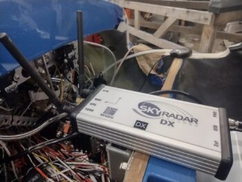
 BTW, if you think this plate is the end of the story for GPS antennas, think again…ha! I have another GPS puck for the MiniUni2 back-up EFIS/timer and another one for the SkyRadar ADS-B IN receiver, over on the left side of the avionics bay. And I’ll go ahead and mention my standalone Dual Bluetooth GPS puck for my iPad. I think I have a spot picked out for that as well.
Lastly, I’ll note that per the Garmin GNS-480 installation manual, NONE of these GPS pucks will be mounted on the aircraft centerline as that honor is the GNS-480’s GPS puck’s alone. In fact, none of the GPS pucks are on the same plane in relationship to each other (close, but not directly) front-to-aft in the bird.
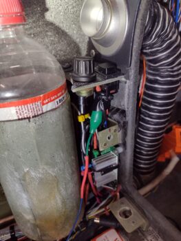
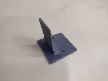
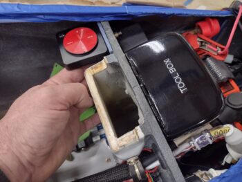
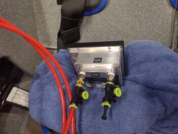
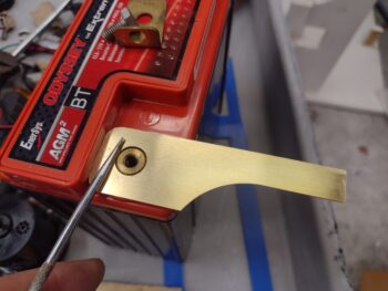
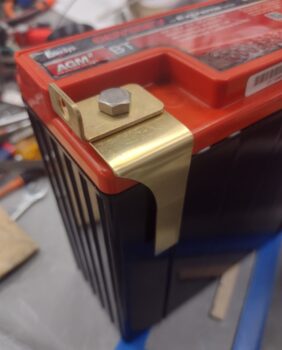
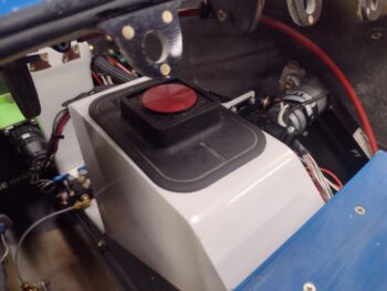
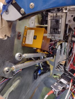
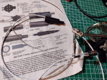
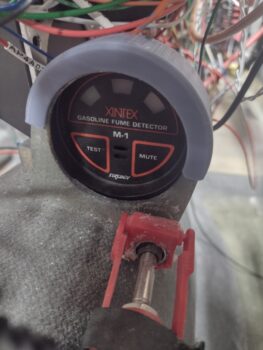
For more than a week now I have been designing and printing out a sleeve that in effect clamps the Fuel Fume Detector onto the AFT side of what was supposed to be its “panel” mount. However, due to the very short throw on the nose hatch door cable handle release (<1/4″) I felt I should have a positive block to keep from inadvertently ‘popping the hood’ inflight. That latch handle block intrudes into the space for mounting the fume detector in a normal instrument install fashion.
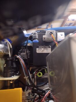
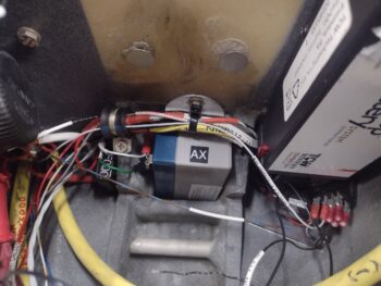
Now, that all being said, after the 4th iteration of this sleeve, and it fitting very well (there is nothing else holding the instrument in place at this point in this pic), I figured I should wire it up and test it out before I glue this sucker into place. The control head (in the pic) tests out fine, but there is a bit more detailed test to do with the sensor, which is back by the GIB seat bulkhead. Once (and if) that is good, I’ll install this unit with RTV.
 I guess I should remind ya’ll that the fuel vapor sniffer above is meant to be just a temporary install to ensure that there is no fuel vapor in the cabin during the first 3-6 weeks of actual flight operations. After it proves no fuel vapors present my plan is to remove it. I picked this idea up from the VANs bubbas on the VAF forum. However, if I need to plunk down any more serious cash for a new sensor, I very well might just punt and scrap the whole idea.
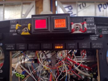
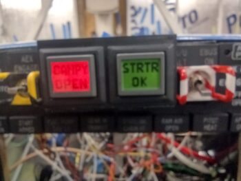
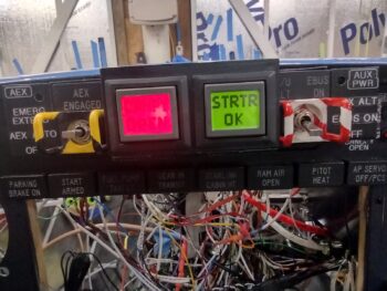
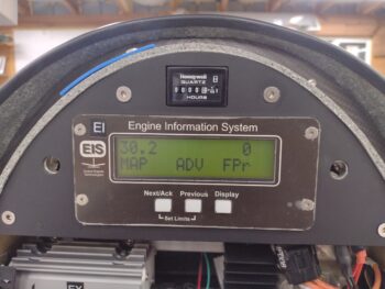
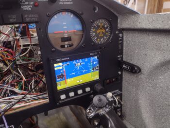
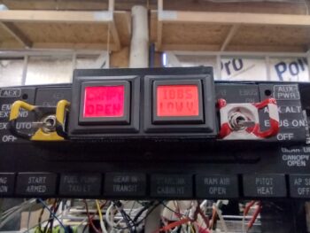
I also wanted to quickly show you what I see currently when I fire up the Master Switch on this bird. I already mentioned the red CANOPY OPEN alarm on the left AG6. Well, after a few days use with no actual recharging going on, I now am getting an amber IBBS LOW V[olts] alarm on the right AG6. I guess these are letting me know they’re working eh?
 Now, how about that Landing Brake?
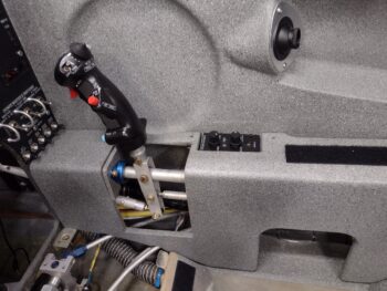
Many moons ago when I first posted my switch configuration on the throttle handle, I got a call in short order from my buddy Marco, an airline pilot. He chewed me out, called me stupid and said I needed to get my sh*t together regarding my switches!! (ok, I might be embellishing a bit… haha!).
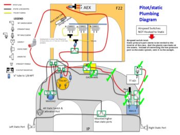
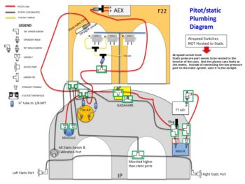
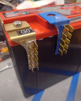
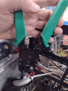
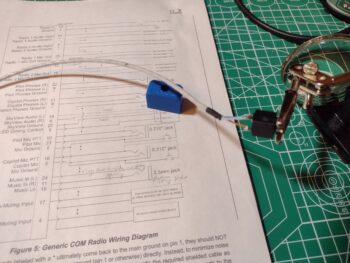
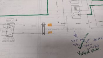
In all seriousness, he mentioned the aviation standard, at least in the airlines, is during a go-around that all levers and switches go forward, and I had my Landing Brake switch with forward DOWN and aft UP. You learn something every day, huh? And looking at the diagram, which is a near exact copy of Jack Wilhelmson’s diagram, I simply reversed the leads to the switch to meet this newly learned standard (pic 1).
-
-

Now, I have recently dealt with how confusing this diagram is (to me anyway) and even had to recently rewire something that I misinterpreted since the diagram is not easily transposed into the physicality of its wiring in my bird. And as my wife was making dinner tonight, I had an aha moment and realized exactly what was going on:
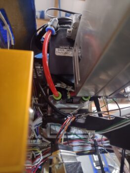
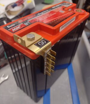
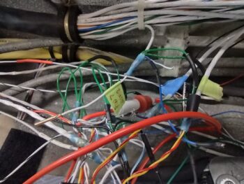
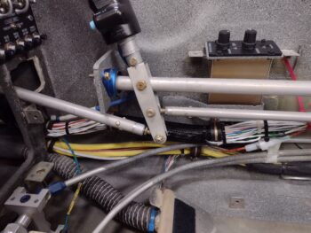
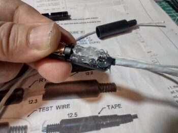
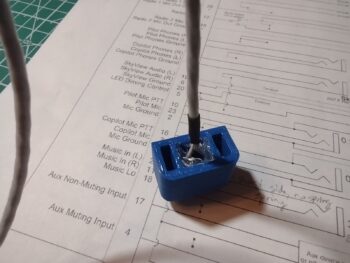
⇒ I had swapped the wires UPSTREAM of the switch and relays vs DOWNSTREAM where it simply swapped up vs down per switch input. I needed to set those leads back to what they were, and swap the actual power/ground (which flip-flop depending on switch position) wires to the actuator itself (pic 2).
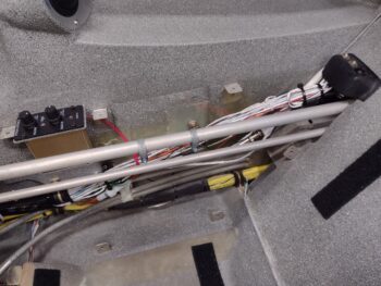
After getting into the P4 connector and swapping the wires back as per my original diagram, my point of swapping the Landing Brake power leads was under the pilot thigh support just aft of the ELT (which I obviously dislodged temporarily for this task).
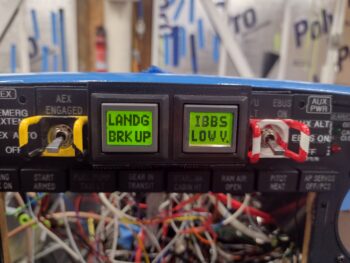
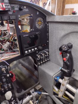
 Voila, it worked! The Landing Brake operated per throttle handle switch labeling, with down kicking off the amber LANDG BRK DN AG6 alert (pic 1), and then when I flip the switch to up I get the green LANDG BRK UP notification (pic 2… not sure on the green IBBS Low V on the right. Probably need to tweak that alarm input parameters). Moreover, full throttle resulted in the Landing Brake automatically closing.
Task complete.
Now, I failed to get a shot of this yesterday, which is simply a single light for GEAR IN TRANSIT when the gear is going either up or down… that replaced the 2 separate gear up/gear down lights. Still, it is notifying me so I’m calling it good!
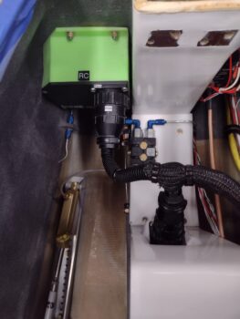
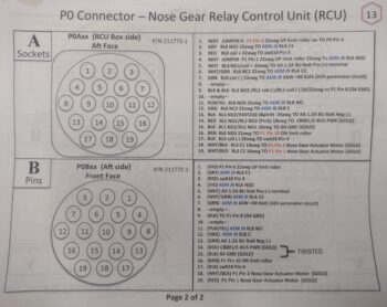
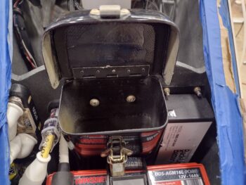
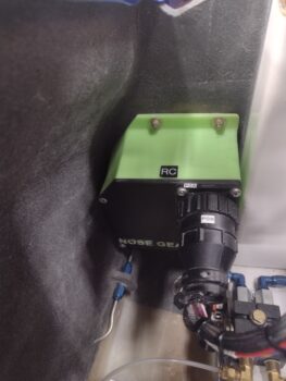
 I then spent well over 2 hours tracing and performing continuity checks, taking voltage readings, etc. on the nose gear down no-go issue. After all that work, I finally narrowed the culprit down to 2 possible wires in the P0 connector OR a single relay post connection inside the RCU. That being said, as I was checking continuity and failed to get any tone, when I re-positioned the lead and bumped the wire bundle I got tone. I then quickly connected it all up and got the gear to travel down for about 5 seconds. That told me I have a contact issue in either of the two wires I targeted.
 Since it was very late, and I spent way more time than I expected on my troubleshooting, I called it a night and headed into the house. I’m very confident that I’ll figure out the gear down issue tomorrow and get ‘er fixed.
Fighting on!

 All but for that GRT serial adapter. With the TruTrak ADI installed there is simply no room for the adapter. I figured we’re talking electrical signals here, so a quick call to GRT to let them know my eevil plan to remotely mount their serial adapter… that ironically let’s one remotely mount the transponder. They saw no issue with my scheme.
 A correct rewiring of the AP SERVO indicator light should have it back in the mix in short order.
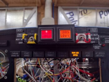 Nice… another power-up test on another component circuit tested good.