Chapter 16/17/22 – AP Pitch Servo

Today was all about getting the Trio Pro Pilot Autopilot pitch servo mounting bracket glassed in place on the right fuselage side wall.  Since I prepped everything last night, it allowed me to just jump into the fray this morning.

I started by cleaning off the Clickbonds with Acetone & then adding a dab of 5-min glue to the bottom of each one.  I had them in place in the mounting bracket to allow me to align the Clickbonds to the actual pitch servo bottom mounting plate when I glue them to the sidewall.

5-min glue on Clickbonds

I then lined up the whole assembly and pressed the Clickbonds into place onto the fuselage sidewall.  I held it there by hand for about 3 minutes to ensure the 5-minute glue set up.  I kept the bottom edge of the mounting bracket aligned with my angled alignment mark that I had made on the side wall, and my left-right alignment was my arrow on the lower left corner of the mounting bracket that aligns with the intersection of the slanted alignment mark and a point 7-3/4″ aft of F22.

Mounting Clickbonds- mounting plate template

After a few more minutes I pulled off the mounting bracket from the Clickbonds, and after a few double-checks on their alignment, let them cure.  The middle dark area just to the right of the left row of Clickbonds is actually a 2-ply BID layup I threw on the side wall to help fill in the elevation gap between the uber 4-ply BID that secures F22, and the sidewall just aft of all that thick BID pad [not a big deal, but perhaps the install could have been better engineered by the Trio gang to avoid this 4-ply BID pad-to-sidewall transition area?….still, no big worries].

Clickbonds mounted in place

As the Clickbonds cured I whipped up some epoxy and wet out the prepregged 3 plies of BID.  I then used the mounting bracket to mark the BID to allow me to cut small holes in it for the 6 Clickbond access holes.

Marking mounting holes on prepreg

I then whipped up some flox and applied it around each Clickbond base and in the transition area to provide a straight foundation for the mounting bracket.

Flox fill for irregular sidewall surface

I then laid up the prepregged 3 plies of BID.  While the prepreg plastic was still on, I taped up the bottom of the pitch servo for anti-gunk protection and used the actual servo to press in on the flox to attain the exact amount of flox angle required for the servo to sit flat against the sidewall.

3-ply BID prepreg laid up

I then pulled the peel ply top plastic, applied a bunch more flox and then set the mounting bracket into place.  I then laid up the 2-ply BID prepreg over the mounting bracket. Again, with the prepreg plastic still on, I once more set the actual servo on the Clickbonds and applied firm pressure to set the mounting bracket, flox and BID plies into place.

Mounting bracket floxed in with 2-plies BID

I then pulled the prepreg plastic and peel plied the entire layup.

Peel plied AP pitch servo mount bracket layup

Today was a short work day since I helped an Air Force buddy that just arrived into the area move some furniture.  Tomorrow I’ll pull the peel ply and clean up this layup.  Then I’ll mount the pitch servo.  I also need to reset the mounting bracket inside the Infinity stick grip because the plastic handle halves are misaligned just a bit, and it’s creating a ridge down the center of the grip stick that will annoy the snot out of me if I have to fly with it! With that, I’ll continue to work the main fuselage/cockpit flight controls as much as possible until I can’t continue (i.e. no firewall aft controls) and I expect to be getting back to the wheel pants next week.

Chapter 22 – Trio A/P pitch servo wiring

I didn’t really get anything major done today on the Long-EZ build.  I did watch a fair amount of football and did a good bit of research for tomorrow’s build activities.

One thing I decided to knock out was swapping out the wiring connector on the Trio Pro Pilot Autopilot from a Molex connector –which by now you probably know that I don’t care for– to an AMP CPC connector.

Trio pitch servo wiring

I started by removing the individual Molex pins from the Molex connector housing.

Trio pitch servo - Molex removed

I then cut off the Molex pins from each wire.

Trio pitch servo - connectors removed

I added a couple of pieces of shrink tubing both at the strain relief point coming out of the servo housing, and another piece that will end up close to the connector.  This latter piece will not only serve to help with strain relief, but also to maintain a good bit of twist in the wires for dampening any errant electromagnetic radiation.

Trio pitch servo - prepping wires

I had spent a good half hour confirming & updating the wiring schema from the Trio Pro Pilot manual. However, I didn’t confirm my original claim of pins vs. sockets on my sheet. My bad since I went with pins here, when I should have installed sockets.

Trio pitch servo - AMP pins installed

No big deal.  Normally pins or sockets wouldn’t matter, but since my pin side connector body has a flange on it, I had originally meant for it to stay hard-mounted in the aircraft, while the servo side connector would be removable (no flange).  It will mean just a slight modification to the mount on the side wall of the fuselage, meaning although this connector will be screwed in place it will also be easily removable.  I’d much rather do that than cut off perfectly good (and crimped!) pins and waste time & money for a slight re-tweaking of the P3 connector installation.  I mean, after all, how often am I really going to be removing & installing the pitch trim servo after it’s initially installed? (not many I hope!)

Trio pitch servo AMP CPC connector

Tomorrow I plan on focusing on finalizing the elevator control tube installation (flight controls) and the mounting of the pilot control stick grip.  In addition I plan on prepping the install of the autopilot pitch servo (above).  I’ll also most likely do some minor tweaks to the canard filler pieces as well.


Chapter 22 – Why Vic?! . . . Why???

It’s funny to me how I can ponder on something for a fair amount of time and then as if by putting mental energy into a concept, it reveals itself in a some what short amount of time. As with many things lately, certain discussions have fostered various thoughts about various instruments, avionics and switches on my panel.  Yet another discussion I had with Marco about his recently purchased Long-EZ –which incidentally has proven to be quite the test bed in that the handful of discussions that we’ve had concerning his new bird have spawned a number of viable system designs mods in mine– and the comment that he made on wanting to have a Garmin-free bird (due to their high prices on data updates), got me to thinking a bit . . .  but admittedly, with everything that’s been going on lately, I really wasn’t thinking that much on it!

What I had been thinking about for some time was having a GPS with a decently larger screen size than the GTN650, but one that would still fit comfortably in my panel.  In fact, I was thinking about this even more after I learned that GRT had debuted (FINALLY!) the 8.4-inch HXr at this year’s SNF.

Well, not sure if you got a chance to read Vic Syracuse’s article on the Avidyne IFD540 GPS Navigator in the August 2016 edition of Kitplanes Magazine.  All I can say after doing a bit of research for the last 3 days on this puppy is WOW!  This guy is packed with a ton of features, and in addition, its screen size falls right in between the GTN650 and the GTN750, so it looks like it will really work well for my panel size.

Avidyne IFD540 GPS Navigator

Moreover, the Avidyne IFD540 is a drop in replacement for the Garmin GNS430, so the pinouts are nearly the same as it is with all Garmin GPSs.  I spent about a half hour confirming and updating all the component crosslink pins to ensure that this would work in my electrical system’s wiring schema, and it does!  I had to change the actual pin ID numbers on about 70% of the pins (the D-Sub connectors identifying numbers are different as well), but did the swap in my wiring diagrams in short order.

And yes, I did say last week that I was done with my electrical system planning for the time being, but apparently this is the nature of the beast in building a homebuilt experimental airplane.   So again, I think I’m done in having finished my electrical system planning (at least for now!).

Chapter 22 – A few Yays & an Oops!

Over the past few days I’ve pretty much finalized all I can with my electrical system planning at this time.  I would hazard a guess that over the past couple of months I’ve moved the “finish” dial on my electrical system design & documentation from the 89-93% range to the 96-97% complete range.  There are still a few more admin things I need to finish, and depending on any future changes in vendor-mandated installation requirements on my respective components, I’ve pretty much got the design dialed in to the point where I can implement the electrical system plan where permitted from here on out as I build.  I do have a couple of switchology decisions to make, but those won’t come until I mock up the panel and play around in a simulator-type setting while making airplane noises.

Moreover, I met another design milestone by creating wiring diagram 13 showing all the wiring for the 6 throttle handle-mounted switches.  Since I’m making the throttle handle removable I’ll be running all the wires through a 24-pin AMP CPC connector–the same style connector that I used on the nose gear actuator connectors where I swapped out the stock Molex connectors.  On the throttle handle I’ll be wiring all the switches with new wiring and swapping out the old stock circular Amphenol Mil-Spec connector with the much lighter and cheaper TE Connectivity AMP CPC connectors.

24-pin AMP CPC connector vs old

After removing all the existing electrical potting material and then stripping all the throttle handle switches of the myriad of resistors and capacitors, which created a near-impenetrable labyrinth around the back side of each switch, I was able to tone all the switches out.  I was pleasantly surprised to find that I had mistakenly ID’d the bottom toggle switch as a SPST switch rather than the DPDT switch that it actually is.  I had already targeted an $80 OTTO replacement switch for this position, but after this latest round of investigation I can belay that order and use the stock switch for my Landing Brake!

With my throttle switches clearly identified, and the wiring to & from each switch, I could then marry up my initial throttle switch diagram with the 24-pin AMP CPC connector and finalize the throttle handle’s P4 connector pinout diagram.  I have all my multi-pin circular connectors detailed in a PowerPoint slide deck (it just evolved that way).  And since I currently have seven connectors on the aircraft (P1-P7), I obviously need a diagram for each connector.  Unfortunately, I hadn’t created all the diagrams, so down another rabbit hole I went for a couple of hours to finish all the templates for all the circular connector pinout diagrams, as you can see in the pic below.

P1-P7 Connector Pinout Sheets

Now, each connector pair gets 2 pages detailing the pin assignments.  The first page (top of the 3 pages in the pic below) details the general information about each connector: number of pins, part numbers, mounting flange (if present), hole number schema, pins, sockets, and standard vs reverse sex connector.  The second/back page (middle & bottom in pic below, with bottom page info populated) shows the detailed pinout for each connector side, with wire colors and wire function/connectivity.  I of course finalized populating all this information for each side of the P4 throttle handle switches connector.

AMP CPC pinout diagrams

As for wiring diagram 13 depicting the wiring for all the 6 throttle handle-mounted switches, below top you can see the initial draft versus draft #3 in the second pic below.

Throttle Handle Switches

Throttle Handle Switch Wiring via P4

I knew that the top left throttle handle switch that was clearly designed for a specific F-15 system was not going to work for my application.  This switch is nearly heavier than all the other switches combined and in my estimation is probably a good 30% of the stock weight of the throttle handle as it was shipped to me.  I pulled this switch and then spent a fair amount of time identifying its replacement.

Removed F-15 throttle handle switch

And here’s what I came up with: the OTTO T5 mini trim switch.  The more complete description is a commercial grade 4-way plus center pushbutton trim switch.  The pic below is a stock photo off the Mouser website.  In actuality, the switch I ordered does have the “stadium” grips on the top as this pic shows, but it differs in that my switch is gray and it is press fit vs. threaded mounting.  If you’re curious about the switch assignments, here they are:

  1. UP – Trio Autopilot Fuel Information Screen Cycle
  2. DOWN – AFP30 Air Fuel Data Computer Screen Cycle
  3. LEFT – GRT HXr EFIS Page Flip
  4. RIGHT – Garmin GTN650 NAV Source Select
  5. CENTER – Garmin GTN650 CDI Source Select

OTTO T5 Mini Trim Switch

As for the other Throttle Handle Switches, here’s the layout:

#1 – Outboard Front – 5-Position Mini Switch (described above)
#2 – Inboard Front – COM PTT
#3 – Inboard Side Top – COM1 Freq Flip-Flop
#4 – Inboard Side 2nd Down – Nose Gear UP/DN
#5 – Inboard Side 3rd Down – A. Remote Start Arm   B. Trig TT22 XPDR Ident
#6 – Inboard Side Bottom – Landing Brake UP/DN

Throttle Handle Switches

Alright, moving on!

As I was reviewing the P-connectors pinout diagrams, I set about to confirm some info on my P3 (Trio autopilot pitch servo) & P7 (Trio autopilot roll servo) connectors.  For some reason our good friends building non-TSO’d products for our birds typically use auto grade Molex connectors.  Being a true disciple of Bob Nuckolls, and having had other discussions with some smart bubbas on this topic, I am simply (and clearly) not a fan of Molex connectors.  Especially for the autopilot roll servo which will be located on the back of the center section spar in the engine compartment.  I want more environmental protection for this connector.  So, my dear friends, I was confirming the wire colors and pinouts on the P7 connector with the Trio install manual–since I had just ordered a reverse sex 4-pin sealed connector (so that it was physically impossible to connect up either servo in the wrong spot) on my last Mouser order– AND that’s when a disturbing question popped up concerning both the P3 connector, and the pitch servo.

You see, I had incorrectly ordered a 4-pin connector for the pitch servo in my haste to get all the required electrical pieces parts in hand.  It didn’t require any O-ring seals since it was in the avionics bay, so I simply pulled the trigger.  But while reviewing the Trio autopilot installation manual wiring diagram, I realized I had forgotten about the 2 extra wires coming from the pitch servo for the Auto Trim feature.  But why had I forgotten these wires?  I then pulled the pitch servo out and –what?!– only 4 wires!  Hmmm, maybe they were tucked inside the servo since this was an “optional” (key word here folks) feature.  I pulled the cover off the servo, and no joy.  There was not an extra pair of wires or connection points inside this servo.  Ok, what’s going on here?

I went to Trio’s website, and I still got the impression that the Auto Trim feature was a standard feature of Trio’s Gold Standard servos and merely labeled as “optional” since the builder had to add a relay, bridge rectifier and wire it all up for it to work.

Trio Autopilot Pitch Servo

I called Chuck at Trio to ask him about this latest puzzling revelation.  He and the Trio gang were just getting ready to head out the door to Oshkosh, but he took the time to have a detailed conversation on the status of my pitch servo.  So here’s the deal: A few years ago the Auto Trim feature was an actual priced option for the Trio Gold Standard servo. However, they decided to simplify production and simply make the Auto Trim a standard feature on the pitch servo, yet still optional as to if the builder/owner wanted to utilize it or not.  Since this was my impression all along, it never entered my brain as a data point when I bought these servos from a fellow homebuilder (Rans S7 I believe) off of Ebay.  If you recall, I had the servos sent straight to Trio who made one engineering upgrade, ops checked the servos and then sent them on to me with the install kit required for a Long-EZ. All was good!  Or, so I thought.  Hmmm…

Trio Autopilot Pitch Servo

Okay, lesson learned!  The money I saved on buying these servos off of Ebay has been reduced to virtually nil now that I’ll be sending the pitch servo back to Chuck, along with a couple hundred bucks, to have the Auto Trim feature installed.  All in all, no big deal.  I’m just glad I caught it early on.  And I guess technically this was two Oops since I also had to spend $10 to include all the pieces to make up a 7-pin AMP CPC connector on my last Mouser order!  [Note: I’m using a 7-pin connector since they don’t make a 6-pin.]

In closing, I currently have everything either on hand or on order for my electrical system. As I did a couple of years ago, I’ve included a rundown below of all my electrical system diagrams (wire book) up to this point.  As you can see, I have a few more systems to figure out, but nearly all of the really critical stuff is complete.  As for the Main, Battery and E- Busses, I won’t diagram those out until all my other system designs are completed and installed.

0. Index Page
Z.  Z-13/8 Electrical System
A.  Switches, Circuit Breakers & LEDs
.99 Grounding Busses
1.  Panel Components
2.  Radio & audio system
3.  Panel Power
4.  Electrical System Components Location Diagram
5.  Aircraft Wire Labeling Sectors Diagram
6.  Nose Gear
7.  Pitch & Roll Trim Systems
8.  Lights: LDG, TAXI, NAV, STROBE
9.  Engine Info Management
10. Fuel System
11. Cockpit Lighting
12. Landing Brake
13. Throttle Handle Switches
14. Control Stick Switches
15. Integrated Backup Battery System & X-Bus
16. Alarm & Warning Systems
17. Charging System
18. AG6 Warning Annunciators
19. Electronic Ignition
20. P-Mag Ignition
21. Heater System
22. Starting System
23. ELT
24. Heated Pitot Tube
25. Trio Autopilot
27. Main Bus
28. Battery Bus
29. E-Bus
30. Long Wire Runs

This wraps it up currently for my electrical system design and planning.  From here I’m going into house cleaning mode (multiple out of town visitors arrived and/or arriving!) and shop cleaning & organization to move forward on the actual build…  woo-hoo!


Chapter 22 – Trio Pro Pilot on deck!

Today I finally received one of my instrument panel items that I’ve had on the list of things to buy for years now!  About a week ago I pulled the trigger on the Trio Pro Pilot Autopilot control head.  If you recall, I bought the servos from a guy off of eBay a couple of years ago and had them sent straight to Chuck at Trio who upgraded and ops checked them to ensure all was good.

LEZ Trio Propilot

This autopilot unit has the GPS Steering (GPSS) and GPS Vertical Steering (GPSV) options on it, with the GPSS allowing the Pro Pilot to receive GPSS commands from the GRT EFIS or Garmin via ARINC 429 data outputs.  The GPSV allows the autopilot to receive pitch steering commands from a WAAS GPS receiver for precision approaches using GPS.

In addition, after a lot of discussion over the years, Chuck tweaked one of the pull up resistors in this Pro Pilot’s innards so that it can receive fuel data from the FT-60 Red Cube fuel flow meter along with the GRT EFIS.  This gives me fuel management on both the EFIS and the Pro Pilot, which provides some pretty nifty fuel flow information.


Chapter 13 – Pitot tube install

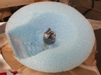
I started off today by shooting my laser down the CL to ensure that the large bolt that I’m using as a clamp to hold my nose tip cone on is aligned in the center, since the hole I drilled in the big block of blue foam that is now my nose cone, was about a 1/4″ wider in diameter than the bolt.  I had to move the bolt over to the bird’s right (pic left) about 0.15″ to get it centered.  With that done, I could then sand the blue foam nose cone down to the big outer washer I used along with the gigantic bolt.

Aligning nose tip bolt

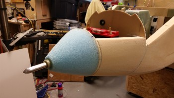
I then gave myself exactly 1.5 hours to sand the nose to shape, for round 2.  Here’s what I came up with on the left side.

Some fresh contouring

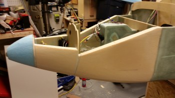
And here’s the right side.

Right side nose shaping

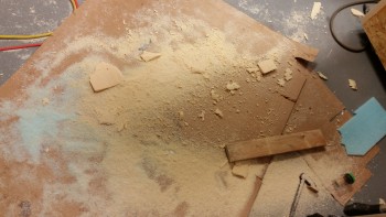
And here’s what was removed in sanding & shaping: Round 2.

Today's nose sanding mess

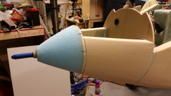
I then ran the requisite “tape measure-over-nose” to get an idea of how my nose was looking profile wise.  I think since I capped my nose cone at a hair over 6″ long, then my nose drops off more quickly than a gradual curve would show if I had added another 2″ to it like my buddy Marco.  But if I did that, I would hear his incessant claim that I was copying his design, so I had to sacrifice style for pride . . . haha!  (I’m kidding!)

You can see what I’m talking about by the approximate inch gap between the tape and the very tip of the nose.

Checking top profile

I think the sharp drop-off curve at the very top of the nose tip is a little reminiscent of the original plans-style EZ nose.  Either way, besides adding more to the front of the nose, there’s nothing I can do about it, so it will get worked into the schema.

Checking top profile

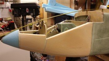
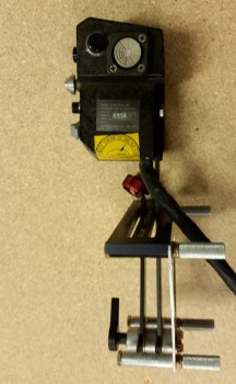
I then mocked up the pitot tube for install.  In its initial resting state in the nose cone channel (where my clamping bolt transited) it sat pointed about 0.1″ off to the left & about 0.1″ high.  I lightly sanded the inside of the nose cone channel a few trial & error times before finally dialing in the correct windage & elevation.

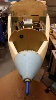
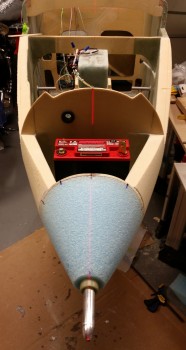
Below you can see my laser sighting of the pitot tube to match it with the aircraft’s CL.

Pitot tube test fit & alignment

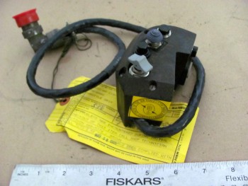
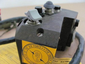
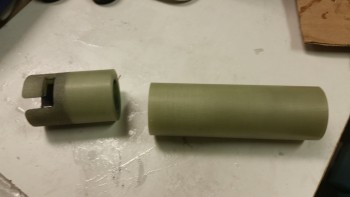
When my incredibly talented buddy Marco machined this magnificent pitot tube, the G10 protective heat sleeve ended up in 2 parts.  To flox this thing in the nose, I didn’t want any flox leaking in-between the two pieces and locking my pitot tube into an eternal position, so I prepped the two G10 tubes to be joined via 5-min epoxy.

Joining pitot tube G10 sleeves together

Here’s my now one solid G10 tube for the pitot tube.

Pitot tube sleeve joined with 5-min glue

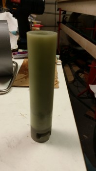
Well, the G10 pieces were a very scant fraction of a millimeter off, but when I ran the pitot tube down to test alignment, it literally snapped the single G10 tube back into 2 separate pieces.

Oh well, on to plan B.  I still couldn’t allow for epoxy or flox to get into that G10 seam, so I taped just forward of it and planned on the first round of flox to secure the first 4-5″ of the G10, then I would deal with the rest after I popped the nose cone off, whittled out the foam and laid up a ply or two of glass.

Pitot tube & sleeve prepped for install

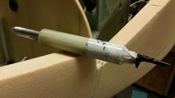
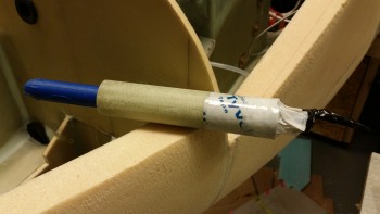
As final prep before I floxed this sucker in place, I taped up the pitot tube with blue painter’s tape.  I wouldn’t want to have a beautiful pitot tube set perfectly in place with globs of epoxy from my ham-fisted install all over it!

Pitot tube & sleeve really prepped for install

I whipped up a bunch of wet flox first and slathered that in the hole, then I followed that up with a flox paste and installed the pitot tube assembly.

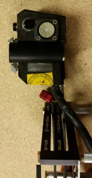
I then laser sighted it again to ensure it was still tracking straight on the CL.

Pitot tube floxed in place & aligned

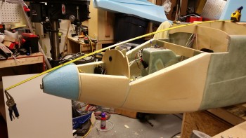
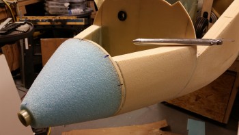
Here’s a profile view of the installed pitot tube.  If the pitot tube looks as if it’s pointing down, it’s an optical illusion.  I swear I saw this pic and thought my pitot tube would cure in a pound of solid flox in the wrong position!  So I double, triple and quadruple checked windage & elevation, and the elevation on this pitot tube perfectly matches the longerons. And due to this pic below, I seriously checked it about every 10-15 during the curing of the flox!

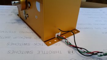
Also, as I was figuring out the spacing requirements for installing the pitot tube, I determined that for clearance of the pitot tube fitting that sits just inside the battery compartment, on the aft side of the F-7.75 bulkhead, that I couldn’t mount the aft end of the G10 sleeve any farther than 1.05″ from the front face of the F-7.75 bulkhead.  When I mocked up the pitot tube install, I found that a 0.5″ protrusion of the G10 sleeve on the front tip of the nose cone equated to a 1″ gap between the aft end of the G10 tube and the front face of the F-7.75 bulkhead.  Requirement met!

Pitot tube floxed in place & aligned

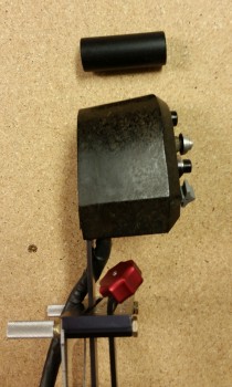
Here’s a shot of the installed pitot tube a couple of hours later after the fast hardener used in the epoxy/flox was getting to a solid green stage.

Pitot tube installed!

I again reshot the laser to sight the pitot tube’s alignment with the CL.  Bravo Zulu!

Checking final pitot alignment with Laser

I spent at least 20 minutes, if not 30, using the L-shaped side of a scribe to dig flox out from around the aft end of the pitot tube fitting and wires that I had previously taped up. The first inch inside this hole, between the front face of the F-7.75 bulkhead and the G10 sleeve is where the fitting and wires attach to the aft side of the pitot tube.  I definitely didn’t need any flox in this area, but there sure was a heck of a lot of it, 90% of which I couldn’t actually see!

Attack of the electrical tape…!

Almost 3 hours later, when the flox was barely gummy and close to a full cure, I removed the pitot tube by rotating it CCW looking from the front of the nose and then pushing it all the way through the G10 & into the battery compartment.  I then cleaned up the pitot tube and set it aside until later.

Pitot tube removed & cleaned

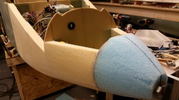
Then, as per my original plans, I applied firm pressure with both hands and wiggled the nose cone slightly until it popped right off the F-7.75 bulkhead.  The 4 blobs of 5-min glue had done their job perfectly!

My removable "radome"

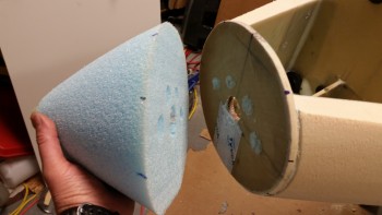
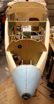
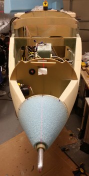
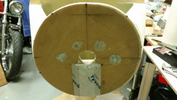
Here’s a shot of F-7.75 bulkhead after I removed the nose cone.

Nose tip removal aftermath

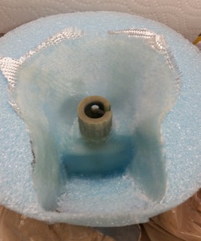
I then set to work to remove the foam in the center area around the pitot tube aft end, including of course the G10.  And then also clear out a channel for the nose mounted landing light.

Measuring out for foam removal

Here’s the beginning of the “Big Dig”!

Removing foam & tape

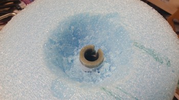
And later on, after I completed the digging out of the pitot tube G10 sleeve (including that tape I had added to protect the seam between the 2 G10 pieces) I cleared out the foam for the landing light.

In addition, I ran a straight edge across the foam & checked the distance from the foam face (front of F-7.75) and the aft edge of the embedded G10 sleeve.  I got 0.97″ using the digital calipers.  Since I didn’t want more than an inch, all is great with this spacing.

Shaped & ready or BID layup

Since I have a decent sized dished out area for the landing light, I wanted to add some more strength internally to the nose cone, besides just relying on the external skin for all the strength.  In addition, I wanted there to be some actual glass securing the pitot tube in place, so I felt an internal layup here would be most appropriate (said in Conehead voice).

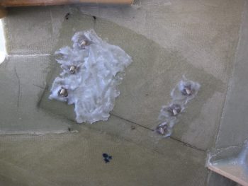
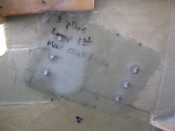
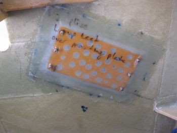
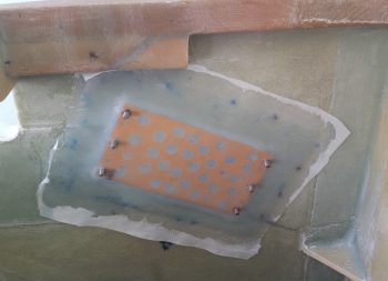
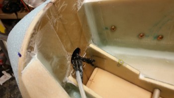
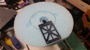
I then glassed in the side walls and upper wall of the landing light area, and the inverted cone area around the pitot tube G10.  Around the base of the G10 and on the upper wall of the landing light (down the front side of the G10 tube as in the pic below) I used a fair amount of flox.  I also used 2 plies of BID on the upper wall/G10 side, whereas I only used 1 ply of BID for the other areas.

Inner nose cone BID layup

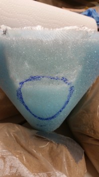
Before I glassed the internal foam on the nose cone (above), I hooked the landing light up to the battery and fired it up.  I then set the nose cone in place, and with the translucent foam –especially how thin it is in the landing light channel area– I could see exactly the size & shape of where the lens cover would need to be mounted.  I marked that up with a blue Sharpie and then pressed on to glassing the interior of the nose cone.

Landing light lens cover area marked

Tomorrow is New Years Eve.  I’ll be working on the project until probably mid-evening, then taking off for the festivities.  I had really wanted to get the external side of the nose glassed before New Years, but with the challenges of the landing & taxi light installs (yes, there will be a separate taxi light! . . . more to follow) I think it will be more like the 2nd or 3rd of January before I get to that point.  I would rather have everything correct & optimized than to meet an arbitrary timeline.

Tomorrow I plan on finalizing the landing light install.  I’ll then also be installing and glassing the center H100 foam piece into the battery compartment between the BC1s.  If that all goes well, then I’ll also reattach the nose cone.


Chapter 22 – More electrons

Today was another bust on getting some shop work in.  Between business calls, meetings and knocking out some personal errands, I just couldn’t get some shop time in.  One thing I could do while I was on the phone was make labels for my electrical components.  So I did.

As many of you may know I designed my electrical system so that I have each component identified with a 2-digit code, and then a 3-digit identifier for the pin, wire  or connector.  Combine this with a 1-letter designator prefix that identifies one of 12 distinct areas of the aircraft, and I then have a resulting 6 digit code that tells me exactly where any wire is coming from or going to, and the device at each end.

So as I was on the phone I simply pulled out the label maker and started going through the list of codes.

Electrical component labels

When I got a chance I would cut a few out and label the components that I have close by.  Since I was in a groove at the end of the work day, I simply rolled into digging into my stores of electrical stuff and labeling a large number of them.  I would say I have about 70% of my electrical components on hand labeled.

Since I was deconflicting and updating my electrical component ID list, this segued into my figuring out more finitely each component installation location in the airplane. I pulled out the Electrical Book of All Knowledge, The AeroElectric Connection by Bob Nuckolls, and reviewed it to make sure I was not straying off the straight & narrow path of good electrical practices.  Especially considering that plastic airplanes amplify a lot of commonplace negative issues that crop up in wiring any airplane.

I also reviewed a lot of other builders’ electrical systems, analyzed those, and emulated a lot of good install how-to’s.  I also jotted down some crude diagrams to look at wiring runs, device locations, etc.  This involved digging out a lot install manuals and verifying a fair bit of information.

By working through what I did last night, I really feel that I confirmed and elevated the completion level of my electrical system design from about 75% to about 90%, and with just a few more minor pieces of information, and perhaps a few phone calls, I’ll be really close to locking in the final locations of nearly all my electrical components.


Chapter 16 – Dissecting the throttle handle

My original thought when I acquired my new F-15 throttle handle was to simply test all the individual pins & create a wire map of all the switch circuits.  Well, with a 37-pin cannon plug, that was a little easier in thought than in practice.  After hunting & pecking for a while, I decided that it was time to dissect the throttle handle and see what exactly I was dealing with . . . and I’m glad I did.

I had already made up a pin-out diagram for the cannon plug & numbered each pin.  Since I wasn’t able to figure out the circuits for the switches or visually see them, I clearly wouldn’t know their functioning until I cracked this thing open.

F-15 throttle handle disection

The first thing I saw when I opened the throttle handle up was the flat joystick-style switch that sits on the outboard, front side of the throttle handle.  It took me a while to carefully dig out the potting material & get the wires situated to the point that I could finagle this thing out of there.  It was a very tight fit!

F-15 throttle handle disection

F-15 throttle handle disection

I then began digging out the other top switch from its potting goop.  I identified the wires & listed them by color on another sheet of paper.  I set about confirming their connections by performing a continuity check by placing one side of my test lead on a switch terminal, then at the cannon plug side I would simply swirl the test lead around until the voltmeter rang out.  Then I would annotate it on my diagram.

Dissecting F-15 throttle handle

After I finished the top switch & had all its info documented, I would then spend another 20 minutes or so excavating the next switch from its potting material prison.  Once its leads were exposed, I again performed a continuity check to figure out the cannon plug pins.

Dissecting F-15 throttle handle

After determining the wiring schema for all the switches on the throttle handle, I discovered some key pieces of information:

a.  I am going to completely rewire the switches in this throttle handle.  Clearly these switches are configured for specific discreet electrical components on the F-15, as evident by the myriad of capacitors, resistors, etc. hanging all over each switch.  Plus, there is far more extra capacity with a 37-pin cannon plug than I am going to need to drive my components with the switches on hand.  My initial thought is that even a 23-pin plug will give me plenty of future scalability.

b.  I’ll be removing the pistol-shaped switch that engulfs the entire interior left side of the throttle handle.  It may provide more capability when linked to specific F-15 systems, but in my case it only offers me a single-position momentary on.  It takes up a lot of real estate and it’s heavy, accounting for almost 20% of the current weight of this handle.  If I get rid of this switch by replacing it with a nearly externally identical Otto switch (with much smaller internal guts), reduce my throttle handle wiring harness by nearly half the wires, and use a smaller plastic AMP connector, I think I could reduce the weight of this handle by about half (about 0.65 lbs).

For those of you that are curious about the current throttle handle switch functions, they are listed below this pic in order starting at the top right-hand switch (flat grey) moving CCW.

F-15 Throttle Handle

1.  Grey flat joystick style: single momentary on (TBD).
2.  Black push button: PTT – single momentary on.
3.  Black push button: single momentary on (GTN650 remote or Trio AP fuel data)
4.  Metal china-hat toggle: ON-OFF-ON (possibly air brake)
5.  Black push button: DPDT dual momentary on (TBD).
6.  Grey-capped toggle:  3-position (broken lead/functioning TBD… ON-OFF-ON?)
_________________________________________________________________________

Also, as I mentioned in my last post, for those of you that are curious about the size & fit of the F-16 throttle handle, I shot a couple pics to show what I was talking about.

F-16 Throttle Handle Comparison

Not terrible at all, but definitely takes up more space than I’d like it to inside the Long-EZ cockpit.

F-16 Throttle Handle Comparison


Chapter 16 – New Throttle Handle

The other night I was on the computer when my Spidey sense started tingling, and I started poking around eBay for throttle handles & quadrants.  For some reason I was off on a mental tangent concerning my throttle handle since, if you recall, in early 2013 in response from a discussion with my buddy Marco, I found a source for some F-16 throttle handles for us.  We both like the thought of HOTAS (Hands On Throttle And Stick), and an F-16 throttle handle, besides being cool, obviously offered a way of putting switches on the throttle.

Fast forward a couple of years, with both F-16 throttle & fuselage in hand, I started realizing that the Long-EZ cockpit is just not that big.  Obviously, the F-16 doesn’t have a lot of real estate either, but the Long-EZ specifically has a narrow left-side console & there’s just not a lot of room for a larger throttle handle taking up a lot space in that area.   In addition, the F-16 throttle handle sticks out over the pilot’s leg, which I could see getting in the way during ingress & egress to the bird.

Now, back to my foray on eBay.  I was actually looking for an F-100 style throttle handle, and found a couple when I searched for “throttle quadrants.”  If you haven’t seen an F-100 throttle handle, it’s rather cylindrical with just 3 buttons on the top.  I was actually thinking of incorporating that style into a new design, and maybe work with Marco to build a unique one out of some lightweight 2024 aluminum.  But right before I logged off eBay, I searched for “throttle handle” and found a military surplus F-15 throttle handle for sale.  It was $69 and seemed to be in pretty good shape (pics below).  I did some quick research & felt it was a good deal, so I pulled the trigger.

F-15 Throttle HandleF-15 Throttle HandleF-15 Throttle HandleF-15 Throttle Handle

Once I received it a couple of days later, I pulled it out of the box and quickly checked the size & fit in the cockpit.  The first thing that struck me was the great fit of the throttle handle in the Long-EZ’s fuselage since the throttle handle’s outboard side is completely flat vertically.  This is of course because technically this is just half, or one of, the F-15’s throttle handle assembly.

Since the F-15 has two engines, this is actually the right-hand engine’s throttle handle and is located next to the left engine’s throttle handle in the F-15.  If I remember correctly (I supported F-15’s years ago at Langley AFB), they are typically physically paired so they move in unison, thus their mating edges are completely flat . . . which again works perfectly in a Long-EZ!

F-15 Throttle Handle

Curiosity got the best of me so I pulled out the existing throttle quadrant and laid the new F-15 throttle handle next to it.  As you can see from the pic below, the new handle is only slightly wider the existing black plastic tube handle only because of the switches mounted on the side of the F-15 throttle handle.

BTW, the cost of those aviation grade switches alone was a big factor in my thoughts on this being a great deal.  Unfortunately, as you can also see in the pics, I’ll have to spend some time on cleaning up the surface of the new handle too if I want to improve its curb appeal (which I will).

F-15 Throttle Handle

Now, every once in a while when I’m off on one my quests to incorporate some unique “unauthorized” modification to my Long-EZ, and am way, way off the path of approved build actions, I actually get a break.  Not just a break, a BIG break that makes something really EZ to incorporate into the design.  Thus, was the case with this throttle handle.

Remember, I had originally just opened the box to ensure that what I had purchased was correct and undamaged.  But after checking the size & fit in the cockpit (GOOD!) and the initial size & fit on the throttle quadrant (GOOD!), I noticed the throttle handle had 3 threaded attach points on the outboard (flat) side of the handle.  These 3 points all were threaded for AN3 (3/16″) bolts, which is exactly what was used to hold the black tubular handle on the the throttle quadrant that I have (AWESOME!)

I quickly took off the existing tubular throttle handle and within mere minutes had the new F-15 throttle handle MOUNTED to the throttle quadrant.  Clearly I’ll have to drill a second hole to finalize the installation, but that will be all that’s required to physically mount this throttle handle.  Of course I will have to contend with routing the wiring as well, but I don’t see that as terribly difficult.

F-15 throttle handle attach

One important note on fit: you’ll notice that with the attach point of the throttle quadrant lever being located close the center of the new throttle handle, the overall space used to employ this throttle handle in the cockpit is quite negligible.  It literally just adds a hair more aft of the original handle, a little over an inch to the front, and the vast difference in height between old & new is minimized by mounting the new handle “low.”  Thus, there’s really only a true height increase of the throttle quadrant by about 1.5″.

In fact, I keep a small whiteboard on the door of my shop for taking notes, listing glass cut schedules, etc. and I use it constantly throughout my build sessions.  I don’t usually show my chicken scratchings on this blog, but here are the size differences I noted between the two throttle handles:

Old/new throttle handle dimensions

With my NEW throttle QUADRANT assembly in hand, I then checked to see how it looked & fit in the cockpit.  In my opinion, it fits like a glove & is exactly what I was looking for… I couldn’t be happier!

F-15 Throttle Handle

Here’s a side view of the freshly mounted throttle handle.

F-15 Throttle Handle/Quadrant

And a view from front looking aft:

F-15 Throttle Handle/Quadrant

I snapped a few shot to show the size comparison between the old throttle handle & the new one (note the old handle resting on the new one).

F-15 Throttle Handle/Quadrant

And an aft view.

Throttle handle size comparisonsAs you can see, the new F-15 throttle handle fits much better than my existing F-16 throttle handle (I guess I actually didn’t show the F-16 handle, so I’ll try to get a pic of that in a future blog post). It’s a little ironic, because as I mentioned before I actually worked on & supported F-15s while in the Air Force, and although I was trained on F-16s, I was never stationed where I was in direct support of them.

Another point in this handle blowing the F-16 handle out of the contest, is clearly this handle comes with switches mounted!  That makes the task of identifying and employing switches for the landing brake, PTT, COM flip-flop, etc. much easier.  Over the next week, I’ll be identifying the wiring schema for the throttle handle, and figuring out how the handle-mounted switches will be incorporated into the overall electrical system plan.

A quick clerical note, I’ll be posting this both in the Chapter 16 (Controls) & Chapter 23 (Engine) build log sections of this site (the original F-16 throttle handle posts were listed only in the engine chapter).