Chapter 19/25 – Shop musical chairs

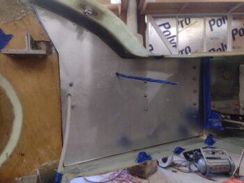
I started off this morning meeting Guy out at his hangar to start the task of reinforcing his right gear leg, that has had a persistent issue with brake heat warping it outwards, causing even more heat issues once the brake rotor contacts the heat shield.

We’ve deduced from a few data points that his ol’ skool football wheel pants are definitely exacerbating the heat issue, since after the first repair things were pretty good until the wheel pants went back on.

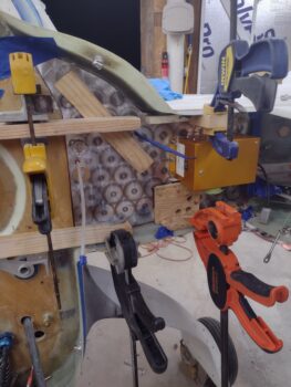
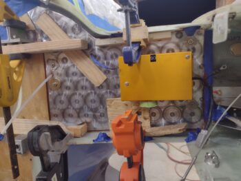
So before doing any radical or high cost fix actions (i.e. new gear bow or an aluminum “sock”) I proposed we attempt a reinforcement of the gear leg —after yet another heating and repositioning inward— with a good number of mixed plies of BID and UNI using a high temp resin to help resist any heat damage.  These plies will not only serve to reinforce the gear leg that has had a few cycles of heat⇒outboard, heat⇒inboard, but as a physical insulation to the generated heat.

I started at the top (~10″ up) with a single ply of BID, then starting an inch down from that a double wrap of UNI @ 30°, then an inch down from that a single ply of BID, then yet another double wrap of UNI biased 30° the opposite direction of the first, and then a final wrap of BID an inch down from that.  So 7 plies minimum, with maybe another ply or two one side or the other depending on where the glass wrap ended.  I then peel plied the layup.

After lunch we came back to the hangar, and with the hot days we’ve still been having the layup was in a nice “green” state of cure.  This allowed me to fairly easily razor trim the glass from the lower gear leg where the brake caliper notch is located, as well as along the very bottom of the gear leg.  We then left it to cure for a few days until we get back to it.

I’ll note that in addition to the added glass on this gear leg, since Guy has Cleveland wheels and brakes, the rotors are just uncomfortably close to the gear leg, especially with a heat shield in place.  To help remedy this issue, I’m going to machine a 1/4″ thick spacer to kick the entire wheel assembly outboard and off the gear leg just a bit.  This will also allow us to put a thicker (0.063″ vs 0.02″) heat shield in place that also covers more of the brake rotor to help block the radiated heat.  We’ll be installing these spacers and new heat shields on both wheels to keep them symmetric.

Back in my shop, I got to playing “musical chairs” in moving stuff around and out (canard back in house) to allow me to wheel in my old taller wing dolly… that the wing will sit on upside down as I finish both the bottom side of the wing-winglet fairing and the underside outboard wing/winglet micro finishing.

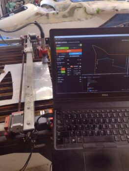
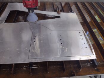
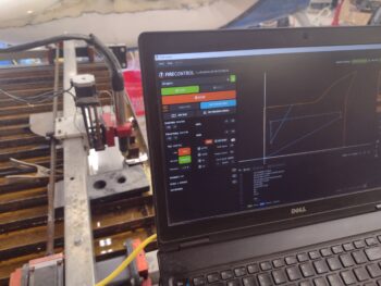
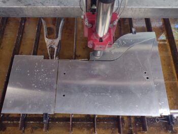
You can see that I was able to move the nose of the bird away from the plasma cutting table and the whole bird back a few feet to allow me enough space to wheel in the old wing dolly.  That being said, things are still tight back there.

I should note that a bit before my musical chairs shenanigans, I pulled the peel ply off the top lip underside layups of both the left wing and left strake.  I then trimmed the glass a bit and added some flocro along each lip edge where there were slight chips and imperfections.  I then left those to cure. (no pics)

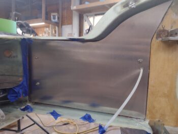
And here we have the left wing inverted on the old, taller wing dolly.  Again, I’ll get to work on the wing-winglet intersection fairing and micro-finishing starting tomorrow.

Yep, slowly pressing forward.

Chapter 25 – Upper left wing/strake lips

Today was all about finishing up the configuration and construction of my wing removal and installation dolly.  And although it required an unscheduled trip to Lowe’s for some hardware, I did exactly that.

Here we have the newly completed wing removal dolly (pic 1), and it in place to remove the left wing (pic 2).

It took about half an hour to remove the left wing as I learned the intricacies of using my new wing removal/installation dolly… since each corner can be raised or lowered elevation-wise using the repurposed trailer wheeled tongue screw jacks.

Not surprisingly, there was a lot of micro dust in the channel between the left strake and wing.

And a good bit at the outboard end of the left strake as well.

I’ll note that before I took the wing off, I inspected the wing bolt lengths inside the wing bolt channels.  Both AN8-22A bolts were about 1/8″ too short, so I swapped them out with some AN8-23A bolts I have on hand.

With the left wing off the bird, I then tried my luck at installing the wing root forward heat shield.  Ahhhh!  As I suspected it went right into place…. note to self!

I have to say that I’m really liking this new wing removal/installation dolly so far, since the wheels allow the wing to be very easily repositioned.  This allowed me to easily open up the gap in between the wing and the strake to then allow me to clear out the tape and foam from just under the top inside edge of the intersection flange on both wing and strake, respectively.

After finalizing the cleanup of the left strake’s aft top lip underside edge, I then filled the corner gap with flocro before laying up a 2-ply corner BID tape to secure the underside aft top strake flange to the aft face of the CS spar.

I then did pretty much the same thing on the top flange of the left wing, laying up a corner 2-ply BID tape overlapping from the flange bottom edge to the front face of the sheer web [I’ll note that I built the wings much earlier in the build than what the plans call for —to use as much epoxy as possible that I bought in large quantity while in Germany. So I was still a very new builder and thus why my wing work is not so beautiful!].

I then spent about half an hour cutting glass that I will layup on the bottom of the left gear leg on Guy William’s yellow Long-EZ (early tomorrow morning).

And with that, I called it a night.  Pressing forward!


Chapter 19/23 – Houston: 2 problems

I started out today plotting out the right wing root forward heat shield template to test out the updates I had made to the template diagram.

I had also updated the post processing G-code files for both the left and right wing root forward heat shields, so after I confirmed the right side template was good, I got to work prepping a sheet of 0.032″ thick 6061 aluminum to use to plasma cut out the heat shields (pic 1).

And then cut out the left heat shield first (pic 2).

I then loaded up the right heat shield in my Fire Control plasma cutting software (pic 1) and cut it out as well (pic 2).

And here we have the the left and right wing root forward heat shields cut out of 6061 aluminum.

As a side note, for those interested, my feeds and speeds numbers are about perfect as here are the undersides of those plasma cuts: very minimal dross on the edges.

I had a hunch that this last round of micro additions on the right upper nose, right sidewall and aft right longeron were going to do the trick.  And I confirmed that after a good hour and a half worth of sanding.

I wanted to knock out the sanding at this point in the day (prior to finishing the heat shields), because I was either going to need to add more micro, or finally get to the final round of epoxy wipes on the upper nose, right fuselage sidewall and right longeron.

I did 3 total coats of epoxy wipes, which can be seen in both the pic above and below.

In between the epoxy wipe coats, I was able to get the front and aft tabs of the newly cut heat shields bent as required on the metal brake.

Now, I’ve had a sneaking suspicion that I might have some issues getting the final aluminum versions of these forward heat shields to mount in place vs the thick paper templates, which were way more flexible…. and I was right.  Between tabs protruding from top and bottom, there is clearly a number of CAMLOC receptacles blocking a clean ingress of these shields to get them set in place.

And although cutting the upper corners of the tabs on the left shield allowed me to get much deeper it still just would not set in all the way.  Thus, problem #1.

My thought is to simply get these forward heat shields into place with the wings off, which might lead to another problem—more of a maintenance (and safety) issue if you will: checking the inner wing bolt.  Problem #2.

Currently I have 2 courses of action to remedy the inboard wing bolt checking issue:
A) simply remove the aft heat shield and use a mirror and ratchet extension to check the bolt,
or B) make a small portal with removable cover plate on the heat shields adjacent to the wing bolt.

I’m leaning towards option A to reduce weight, time and effort.

I’ll ponder more on that, but for now I’m calling it a night.

Chapter 19/23 – Yep… heat shields

This post covers the past few days, given we had quite a busy day on the 4th of July, or Independence Day for us ungrateful colonists.

The day before I spent about 4 hours getting the boat ready to take out on the 4th, since I had promised my new bride, Jess, that we could take the boat out for the first half of the day on the 4th.  Then, for fireworks in the evening we had a cookout on a nearby beach and enjoyed those with friends.  That’s my story and I’m sticking to it.

As for the build, yes, I’m still trying to finish up these niggling wing root forward heat shields, although I think I’m very close to plasma cutting them and getting them installed.

My tasks the last few days were all about the same ITERATIVE process for both left and right wing root forward heat shields:

I plotted out the initial right heat shield thick paper template along with the second left side template.

I’ll note that I missed some major dimensions somewhere on the right side when inputting it into CAD, because it had issues.  I simply annotated it compared with the original cardboard template and updated the CAD model… no use wasting time attempting to test fit.

On the left side template, my top and bottom edges were still too big, causing some buckling in the middle areas of the heat shield mockup.  I had a number of tweaks to do on this guy, so back to CAD I went on this side as well.

Which led to the next plotting session, round 2 for the right side (after my initial misfire) and round 3 for the left side…

The left side is VERY close, so much so that I’m not going to remake any more cardboard mockups… a few very minor tweaks in CAD and its ready for plasma cutting (pic 1).

As for the right heat shield mockup, I had a number of significant tweaks that are required (pic 2).  So back to the CAD drawing.

And replot #3 for the right side . . .

And a much better fit this round, but still a few minor tweaks required to dial it in completely.

I updated those needed tweaks in the CAD file, and will plot out another final (hopefully!) thick paper template tomorrow, test fit it and then go from there.

Yes… these darn heat shields (in part due to time off for celebrating Independence Day) are taking way too long.  I really want them done and installed tomorrow.

Rocking on!

Chapter 19/23 – Slow-mo heat shields!

I started off today by removing the aft heat shield on the left wing, then pulled the peel ply and razor trimmed the top and bottom mounting tab glass.

Here’s a shot of the somewhat narrow and tall phenolic bottom tab, secured with flox and 3 plies of BID on the aft side.  I’ll probably add a single ply of BID on the front side.

I then reconfigured my plasma cutting table again as a plotter, and printed out the left wing root forward heat shield mockup on thick stock paper.

After which, I cut out the paper mockup and set it in place in the left wing root.

I should note that I ran downtown for a few hours to run some errands, and during that time picked up two different sizes of plastic grommets for the aileron control tube thru-hole.   This grommet I’m testing below has an inside diameter of 1.0 inch.

In addition, by looking at some bends in the stock paper, you can tell that I need to trim a little more around the edges here and there.  So I’ll tweak the drawing in CAD, reprint and test fit again.

I then made a slew of measurements and constructed an initial cardboard mockup of the right front wing root heat shield.  You can see I’ve already moved the rudder cable transit thru-hole down from its initial position (presence of the green tape).

After getting the rudder cable thru-hole position set, I then opened up the diameter of the aileron control tube thru-hole.  Then, as I did on the left side, I ensured that there was good clearance through the entire control tube range of motion with full left and right aileron deployment.  Full right aileron is shown in pic 1, while the widest part of this aileron control tube is actually a rivet head when the stick is a little past center towards the left (pic 2).

As I mentioned before, I got 2 sizes of plastic grommets while I was out: 1″ ID and 7/8″ ID.  Here I’m testing out the 7/8″ ID grommet, which I assessed didn’t provide enough clearance.

Reading the Canard Pusher and Central States Newsletters, I’ve read a few stories of first flight issues with controls snagging on nearby structures (or thru-holes) with clearances not as big as they should have been to allow for various stresses and pressures during flight.  Thus, my standard for this 1/2″ control tube is 1/4″ all around it. I tried the 7/8″ grommet mostly out of curiosity, and I think it proved my initial minimum 1/4″ clearance requirement was good.

It was getting later in the evening, but I wanted to at least get the initial right wing root cardboard mockup imported into CAD… which as you can see below, I did.  This stuff often takes much longer than expected, and I’m clearly wanting to get it done and in the books to get this bird in the air.

Hopefully tomorrow I’ll be able to get these forward heat shields plasma cut and installed.

Pressing forward!

Chapter 19/23 – More heat shields

I started off today by taking off the aft right heat shield, pulling the peel ply off the new cured upper and lower tabs, and then trimming them with the Fein saw.

Here’s another look at the new upper and lower 90° tabs in the right wing root that will secure the forward heat shield.

I then got to work sanding the current problem areas on the right fuselage sidewall, and some micro fill along the aft right longeron. I sanded all the areas and re-epoxy wiped the aft right longeron and a few spots on the nose, but for the sidewall it needed yet another application of micro, which I mixed up and applied.

Part of my sanding and epoxying wiping tasks was the second round of micro I applied inside the slots across the aft nose substructure just in front of the instrument panel where the 4 tabs on the aft nose/avionics cover drop into to be secured by CAMLOCs thru and around the top of the instrument panel.

I then worked on the aft wheel pants, sanding the epoxy wipes down and then wet sanding them with 150 grit.  I have one small area that needs further work on one side of those (again, no pics).

I then removed the left rudder since when I installed it last I didn’t hook up the actual rudder cable to the bellhorn.  With the cable attached to the rudder bellhorn, I then mounted the oil cooler since the end of the rudder cable bracket is secured to the oil cooler bracket.

With that all in place, and the rudder cable connectors joined, I then simply added a clamp to the nose rudder cable to pull it taut. This provided me the no kidding thru-hole position I needed in the left wing root forward heat shield, which was a good bit different than my original swag.

I then evaluated the position of the other heat shield thru-hole for the aileron control tube with the stick in the full left position/hard left turn (pic 1) and then fully opposite in a hard right turn (pic 2).  As with many things on this plane, the control tube has a lateral movement pivoting aft and slightly down when in a left turn, and forward and slightly up in a right turn.

The next 2 hours were all about setting up, prepping and laying up the upper and lower 90° tabs inside the left wing root, pretty much like I did on the right side.  The big difference that you’ll see when I post next is the bottom tab, which is about half the width of the other tabs since there is a CAMLOC receptacle which I had to avoid just on the edge of the flange.

Thus, for the bottom tab I used about a 1/2″ wide by 1.5″ high 1/16″ piece of phenolic standing on end, which I floxed in place.  I then used 3 plies of BID on the aft side of the phenolic tab that overlapped rearwards onto the wing root surface.  The front of that tab abuts the inside face of the aft heat shield as installed.

I then laid up the top 90° tab the same as I did on the right side, with 6 plies of BID.

I prepped the right wingroot area for creating the right forward heat shield by removing the AP roll servo (after marking the outboard edge which the heat shield flange will have to be notched to avoid), and installing the right rudder cable bracket and cable.  I then removed the right rudder and connected up the rudder cable to the internal bellhorn and reinstalled the rudder.

It was getting fairly late, so I called it a night.  Tomorrow I plan on finalizing both left and right forward heat shields, plotting out templates on the plasma cutting table to ensure they fit correctly in each side, and then plasma cutting them out and bending them on the metal brake for final install.

Again, once the forward heat shields are configured and installed, I am then cleared hot to remove the wings to finish the bottom-side wing-to-winglet fairings and micro finish the outboard bottom wings for primer and paint.

Chapter 19/23 – Foward heat shields

Since my shop was a breezy 99° starting out, I decided it was a great temp to do some sanding! ha!  I spent well over an hour wet sanding the outside longerons, the turtledeck and shoulders, the aft nose substructure, the aft nose/avionics cover front lip (just forward of the canard), and the nose hatch flange.

I then used a pencil to mark up both upper sidewalls along the fuselage and nose as a sanding guide to reveal the low spots that needed micro.  After wet sanding the left side it removed the pencil marks and cleaned up the surface nicely.

The right side however still needed a bit more TLC, so I slathered up 2 decent sized swaths with micro, heavy on the West 410 compound.

I also aggressively sanded the micro on the aft end of both aft wheel pants, and throughout the remainder of the day epoxy wiped those with 4 coats (no pic).

I then turned my sights on a quick task, with the not-so-quick sub-task of finding my the 3-pin Deutsch connector kit I had ordered a couple of years ago.  After 15 minutes of hunting and pecking I found it and installed a new connector half to replace the one I destroyed by drilling out the inside snap insert (still don’t why it didn’t come out as designed) on the autopilot roll servo cable.

Voila!  Here we have the new autopilot roll servo cable Deutsch connector back online.

I then removed all the clamps and wood blocks off the left side CS spar “wing” and shoulder aluminum overlay that I set in place using red hi-temp RTV yesterday.  It’s solidly secured in place, as is the right side, and here are the 2 completed Fiberfrax/ 6061 aluminum CS spar/shoulder heatshields in place.

It was time to get to work on the wing root forward heat shields.  After taking a bunch of measurements and assessing different mounting configurations, I decided to install (layup) a top and bottom tab at the intersection of the forward and aft heat shields, and perpendicular (90°) to the aft heat shield tabs along the edge of the wing flanges.

With both forward and aft wing root heat shields installed, the order from front to back will be aft heat shield with a thru-hole (or slot) for a mounting screw top and bottom, then the top/bottom 90° tabs also with thru-holes, and then the forward heat shield with platenut on the aft side to secure the top/bottom mounting screws installed front-to-aft.

I decided to go with 6 plies of BID for the tabs, starting on the right wing.  And to create the top and bottom tabs, I simply used the taped-up front flange of the aft heat shield for the mold.  I added a piece of peel ply on both top and bottom faces of the tape and wetted those out before installing the heat shield.

I then wet out two prepregged 3-ply BID layups, measuring 2.5″ high x 3″ wide, which I then simply cut in half for my 6 plies.  Again, one for the top and one for the bottom.

The tricky part of course was laying these things up on the aft side of the aft heat shield flange, using a mirror and what I could see through the CAMLOC receptacles to work. I don’t expect them to be picture perfect layups, but as long as they’re structurally strong they’ll do the trick.

On the left side I decided to work the actual forward heat shield configuration and save the flange layup for first thing tomorrow (there’s a CAMLOC receptacle in the way on the bottom, so I’ll ponder a bit more on my gameplan for that).

I started by installing the rudder cable conduit bracket and then inserted the rudder cable.  I also connected up the aileron control tube and installed the aft heat shield.

Again, after a myriad of measurements and some trial-and-error test fits (it’s an iterative process!), I got a good working cardboard template made.  Tomorrow I’ll connect up the rudder cable to the rudder and install the oil cooler to 100% ensure the rudder cable thru-hole is in the correct spot.

I then installed the left wing root aft heat shield to grab these shots of the forward heat shield cardboard mockup, which provides a pretty good idea of how the actual forward heat shield will look once installed.  You can also see how the flanges of the two heat shields will sandwich the 90° mounting tabs and be secured with a mounting screw top and bottom.

Tomorrow I’ll continue working the forward wing root heat shields and hopefully get those knocked out.

Chapter 23 – Final engine turning!

For the record, today was yet another 100° day in the shop… but who’s counting!

I started the day off by engine turning the left side CS spar and shoulder 6061 aluminum overlay.

I then put it in place to see how it looked and grab this pic.

I needed to use some of the clamps and hardware from the right side, so I went ahead and removed all that stuff to reveal the mounted right side CS spar/shoulder aluminum overlay.

Not my best engine turning effort, since I was using a new disc and was having some initial issues with the pressure and it “biting” into the aluminum, but hey, this will be somewhat buried behind the engine and normally under cowl, so I’m calling it good.

As I did on the right side above, on the left I completely covered the Fiberfrax and Thermo-Tec with a thin layer of red RTV.  Since the Thermo-Tec is slightly thinner than the Fiberfrax, I put a few thicker dollops of RTV on that small wedge area.

Then, using a 1/8″ notched trowel I applied the red RTV to the front face of the aluminum overlay . . .

and then pressed it into place onto the Fiberfrax and Thermo-Tec.  I only have 3 Clickbonds on the left side, so I used 2 lengths of angled aluminum held in place with wide washers to press the middle area of the overlay firmly against the Fiberfrax, along with the other perimeter wood pieces clamped into place to also keep the overlay secured.

Of course my payment for the entire task above was being drenched in sweat from head to toe, so I took a quick dip in the pool to cool down.

After changing clothes, I got back to work for a couple hours wet sanding all the areas I had epoxy wiped after either some aggressive sanding, micro-filled holes or pinholes that needed epoxy filling: strake leading edges, upper fuselage/nose sidewalls and the upper side of the nose.

I’ll note that the right sidewall just under the canard is going to need another round of micro, since it’s got a few distinct and offending low spots.  It was getting a little later in the evening, and Jess had made a tasty dinner, so I called it a night.

Tomorrow my plan is to knock out the majority of creating the forward heat shields in both wing roots, which will require making up cardboard templates, importing those into CAD, and testing my templates before plasma cutting/bending them.  Also, I’ll need to layup some tabs for platenuts inside each wing root in order to secure the forward heat shields, so it will take a least 2 days for the forward wing root heat shields task to be completed.

Chapter 23 – CS spar overlays

Last night I prepped my plasma cutter and plasma cutting table to allow me to start cutting metal parts.  I had a little bit of a hiccup with my configuration since I had used my plasma cutter off the table and needed to do some digging in the manual to get the cabling correct.

Once I got it all cabled up correctly, I then set up to plasma cut the right CS spar “wing” and shoulder overlay out of a 0.02″ thick sheet of 6061.

Here’s the result of that plasma cutting job.

At this point in the day my house AC parts were delivered, so I spent the next couple of hours installing those.  Thankfully it appears to have resolved the issue, and my house AC is once again up and running.  We’ll see how long it takes to get the in-house temp back to normal from the current 95°.

I then test fitted the right CS spar overlay, which after some minor tweaks fit very well.

I then set up to plasma cut the left CS spar overlay out of a 0.032″ thick piece of 6061 aluminum.

And here is the freshly cut out left CS spar and shoulder aluminum overlay.

I then test fit the left CS spar/shoulder aluminum overlay, and it fit a treat.  Note the finish on this piece of aluminum, which is pretty good.

However, the right side overlay had water spots and blemishes on the face of it that would not come off with Simple Green, Acetone or white vinegar.  I then tried wet sanding it up to 2500 grit sandpaper before buffing it out… unfortunately it still looked like crap.

Now, my preference —and plan— with these CS spar overlays was to simply cut them, clean them and then mount them.

But I just didn’t want to install an overlay that had some very visible blemishes, so I bit the bullet (and spent 30 minutes looking for my sanding disk) and engine turned the right CS spar/shoulder aluminum overlay.

I then put it in place to grab this shot to show how the engine turning looks before installing it.

I then removed the overlay and slathered up the Fiberfrax and Thermo-Tec shoulder with red hi-temp RTV.

I then applied red hi-temp RTV to the aluminum overlay with a notched trowel (I was rushing, so no pic) and then attached the overlay to the Fiberfrax/Thermo-Tec on the right side.

I temp installed the autopilot roll servo along with wide washers onto all the Clickbonds.  I also clamped pieces of wood in various spots with wedges to keep the aluminum overlay firmly pressed into place while it cured.

Here’s another shot of the installed right CS spar/shoulder aluminum overlay.

Tomorrow the plan is to engine turn the left side aluminum overlay and get it installed, after which I’ll start working on the forward wing root forward heat shields.

Yep, pressing forward… just not as fast as I’d like.

Chapter 23 – Engine bay heat shields

After taping up the Clickbonds, wire cable and rudder conduits, I started out today by slathering up the mating surface of each Fiberfrax piece with red hi-temp RTV and attaching them to the aft face of the CS spar on each side of the firewall, which I also used a small notched trowel to apply the red RTV.

The left side (pic 1) got a little messier than the right side because I had lot more pieces to fit into place, and with my RTV curing on a seemingly accelerated exponential scale due to the shop temp, I had to get these pieces attached post haste.

Yes, not your typical 70° degree shop temp… nope, today was yet another 100° plus day in the shop.

With the Fiberfrax in place over the exposed CS spar areas, I then cut and applied some Thermo-Tec hi-temp shielding to the shoulder areas on the top side, each side.

With my Thermo-Tec supply out and in-hand, I decided to do a few hour detour on a task that I had not yet fully committed on mentally, but decided it was a GO today: applying Thermo-Tec to the inside face of each inboard wing rib.

In my research/final check on how to apply Fiberfrax to the firewall, etc. not surprisingly I read a few horror stories re. engine fires. I figure anything that adds very little weight yet provides precious minutes or even seconds of flight time in the event of an engine fire is worth getting done.  And now was the time to do it.

So I used painters tape on the inside of the left wing to make up a template.

Which I then removed and took inside my lovely HOT house (AC parts due in tomorrow!).

And imported the template into Fusion 360 CAD.

I then again used my plasma cutting table as a plotter and made a line drawing of my inboard wing rib template on thick paper.

After a few iterations inside the wing, I had refined my left side inside wing rib template configuration.

Which I then used as a pattern to cut out a piece of Thermo-Tec heat shield.

I pulled the backing off the Thermo-Tec to expose the adhesive and carefully fitted it into place.

Here’s another shot of the internal left wing rib vertical wall covered with Thermo-Tec high-temp (up to 2000°) heat shielding.

I then flipped the left side paper template over and made a few minor tweaks to match the right side inside wing rib.

And again used that as a pattern to cut out the Thermo-Tec heat shield…

Which I once again pulled the adhesive backing off and carefully applied it to the inside vertical wall of the right wing rib.

I then spent a good hour getting my plasma cutter and cutting table prepped to cut metal, which I will undertake tomorrow to cut the left and right CS spar “wing” aluminum overlays to protect the Fiberfrax heat shielding.  After the CS spar “wing” heat shields are completed, I will then get to work on the forward wing root heat shields, one per each side.