Chapter 13/18/25 – Mystery Screw-Up!

This blog post covers the past few days, where I am still primarily focused on all the centerline areas of the bird in order to finalize the micro-finishing for the canopy intersect areas, as well as the nose hatch and nose.

I started off by adding micro to both the front vertical edge of the glare shield (that makes up the seam with the front edge of the canopy skirt) and the front 1/3 of the left longeron where it interfaces with the canopy edge lip.  I then peel plied both of these micro applications.

The application of micro on the front 1/3 of the left longeron completes the addition of micro along this left longeron for the initial application.  Again, this is essentially a micro hard-shelling task since this addition is too small (IMO) to use pour foam.

A single ply BID tape along this edge seems like it should be a fairly quick job, but it took an entire afternoon.  Here are the aft 2 plies of BID (there were different heights needed to cover the side strip of micro), prepregged in plastic and ready for layup.

After a final sanding of the cured micro strip along the left longeron, and then another application of micro into some of the remaining grooves and divots, I laid up the 1-ply BID tape covering the micro vertical edge and overlapping onto the bare fiberglass just beneath it.  I then peel plied the layup.

Here we have the next day… when I then discovered an issue that for the life of me I swore I had nailed down, since it’s really the core purpose for this task: the new layup over the underlying micro was proud of the canopy edge by a good 0.05″ on the front half of the left longeron.

I was dumbfounded.  I swore I had double and triple checked the edges in relationship to each other on both canopy and longeron.  Of course I was not happy.

Nothing to do but fix this cluster ****!  I grabbed the Fein saw and cut off the glass on the front half of the longeron.  I then stripped off ALL the tape protecting the canopy lip, closed and locked it and then sanded the micro to BELOW/INSIDE the surface level of the canopy lip.

Of course the micro had some significant divots and gouges in it from the Fein saw, so another round of micro was required.

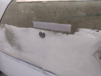
Once the micro was cured, and another round of sanding complete, I then redid the front half layup on the left longeron.  Here is the result of that.

And a shot of the now complete first major task in cleaning up the left longeron and matching it up to look nice with the the canopy frame.

In that vein, I also did a thorough sanding of the right longeron, which I honestly have barely touched since I laid up the top skin of the right strake (pic 1).  To keep the micro jobs manageable, I micro’d only the aft half of the right longeron, including along the corner intersection with the strake top micro (pic 2).

I then did a final cross check of the aft outboard corners of the aft nose/avionics cover where the glare shield front corners start.  I need to round these corners to get those tri-corners dialed in where aft nose cover meets sidewall meets canopy frame.

I laid up a ply of BID each side on the inside of the aft nose/avionics cover, then peel plied both sides of the BID before setting it aside to cure overnight.

I then got back to the right longeron and micro’d up the next section going forward.  Here’s how that looked:

And here’s the entire right side strake/longeron/canopy micro situ at the current moment.  I’ll of course be working this more tomorrow going forward.

Pushing onward!

Chapter 18/25 – More canopy latch tasks

Today I started out by finishing up my micro strip addition just underneath the canopy’s left lip on the forward 1/3 of the canopy.

This micro along the canopy serves a couple of purposes:  First, it essentially serves to widen the longeron under the canopy lip to create a smooth, even flow from canopy lip surface to fuselage/longeron/strake.  This characteristic is more prevalent on the aft half of the canopy to longeron seam.

Second, and possibly more important aesthetics-wise, this micro strip fills in the pronounced original curve of the longeron and creates a straighter line from fuselage/ longeron surface to the canopy lip edge.  This issue is much more noticeable on the forward half of the canopy and increases up to the front corner of the canopy lip.

I’ll note that my finishing “fix” action in regards to this left side canopy lip to longeron interface is essentially a ‘hard-shelling’ operation in that I will sand the micro smooth and blend it in even with the strip of exposed fiberglass just underneath of it.  I will then lay up a ply of BID across this fiberglass-micro junction, covering all of the micro.  This will reinforce the micro and keep it from chipping if a foot, hand, luggage (whatever) dings against it.

I will then finalize the external side of this finishing by adding more micro to connect this new fuselage/longeron-side filler lip to the strake and fuselage side wall.  From there I’ll treat it as a normal micro finishing task as I sand it all to contour and then epoxy wipe [that still leaves the inside edge of this process, which I’ll cover when I get to it].

Now, with the strip of remaining pour foam that I just recently added to the front vertical edge of the glare shield (below), I applied somewhat wet micro to the aft side and top of the foam, before peel plying the foam edge.  Again, this will be somewhat of a ‘hard shelling’ operation as well, in that once I get the foam/micro shaped just right, I will then laying up a single piece of carbon fiber to the glare shield and along this vertical wall of this added foam and micro.  I’ll then deal with the top strip of exposed foam and micro as well (most likely a thin strip of carbon fiber with a flox corner to the previous CF layup above).

My next task involving epoxy was to whip up some wet flox to use in securing the bronze oil sleeve into the canopy latch handle middle block.  Just prior to slathering up the bronze oil sleeve, I hit the outer surface with the Dremel tool to create some flox-gripping grooves.  I then clamped it tightly into place.  Here’s what that looks like:

Now, why did I flox the bronze oil sleeve bearing into the handle assembly middle block?  Well, I noticed just recently that when opening and closing the canopy, and locking and unlocking it as well, I wasn’t getting a full throw of the canopy latch catch hooks fore and aft.

Something was askew… and interestingly I had already taken the pics to show the newly installed canopy latch interior lock when I noted the bronze oil sleeve slipping out of the center block.  Apparently, a week-plus of constant operation on the canopy handle loosened up the press fit between harder bronze oil sleeve and softer aluminum middle block, allowing the sleeve to come loose and exit out of its installed position.  I figured flox (or silicone RTV) was the best way to secure it in place, so I went with that.

Obviously better to have this happen now and find out this issue at this point versus when flying out and about.

I also spent a good chunk of time today assessing and planning out the EXTERNAL canopy handle lock positioning, operation, configuration, etc.  I actually have 2 of these style of locks on hand, one being a bulkier stainless steel lock and the other being a lower profile (chrome?) one.

I assessed the install depth and operation of each lock, and it appeared that the cheaper(?) lower profile lock simply functioned smoother with less fiddly-ness when it came to inserting and rotating the key.  The barrel is also slightly narrower in diameter and shorter, so although it didn’t have the sexier finish between the two locks, it won in all the other aspects.

So here we have the lock position determined and the initial hole drilled into the fuselage sidewall just under the handle.  I have to say I originally planned on placing this lock on the forward (left) edge of the handle, to avoid the 1/4″ Nyla-flo electrical wire conduit running in the sidewall just under the canopy handle (turns out, not the best spot).  Thus, while a royal pain in dealing with my crazy accidental wire cutting issue at the under-longeron GIB Lights switch box… it is now proving quite serendipitous that I had to run those wires under the longeron (vs thru the sidewall conduit) since I will most likely need to cut and remove a decent sized section of the Nyla-flo to create a slot for the lock’s pivoting latch arm.

I’ll continue to work on getting the lock installed into the side wall, with the pivoting latch arm operational, but I am highly considering not machine the interfacing slot into the handle until the exterior paint on the fuselage sidewall is complete (more thought required).

Which leads me to my final task of the evening: sanding the added micro just under the canopy lip on the left side, to ensure a smooth transition from added micro to the fiberglass just underneath of it.

I had planned on doing more work in knocking out the 1-ply BID layup along this added strip of micro, but it was getting quite late and the temp had dropped quite a bit outside,  thus inside the shop as well.  I’ll kick this can ’til tomorrow.

Rock ‘n roll . . .

Chapter 13/18/25 – Canopy latch lock

To be clear, that’s the INTERNAL Lock…

But I’ll first start off by noting that in the push to get the mechanical systems like the canopy latching system or the nose hatch latch configured, the R&D obviously takes up a lot of time and understandably there is a lot of redo’s involved in that.

Case in point is that as I worked on attempting a slight reroute of the nose hatch latch cable —in my attempt to dump the time-busting and involved intermediate bracket— I was 3D printing off my first production version of the canopy latch internal lock handle (in red) vs the previous 3 versions I had made (in black) over the last couple of days (see below), which was further a complete redesign of the first style I created.

That being said, I am happy to report that my nose hatch latch cable reroute worked, allowing me to chuck the intermediate bracket and simply run the cable from handle to latch lever… simplicity in design and function always being best.

As I showed yesterday (while I wasn’t showing all the versions of the internal lock handle) I created a threaded insert to secure the canopy latch internal lock.

Prepping and floxing this threaded insert into the side wall was actually my first task of the day, and here it as installed and cleaned up [Note wires coming from out of sidewall… I had planned on connecting these to a micro-switch mounted inside the internal lock, but there just wasn’t enough room… so the electrical wires are coming out, replaced with safety wire to remotely manipulate the switch —now housed forward of the panel].

And here is the assembled canopy latch internal lock installed.

A few key things to point out:  As I mentioned above, my first design was much larger and focused on latching down on the forward end of the handle.  This caused a clearance problem in both being able to physically grab the handle to open it, AND with the alt-static switch on the panel.  I then simplified the design and made it like a block “C” that simply flips aft over the handle.  My first iteration was, again, too big and I had to bring the size down a couple of notches.  Lastly, the in-wall wire is attached on the bottom arm and pulls the switch (forward of the panel) closed, and small springs manipulate the switch housing and switch open when the internal lock handle is open (forward) as it is here… kinda.

And here it is flipped aft, with the wire pulling the switch closed.  There is a small gap of less than 1/8″ between handle and internal lock, but with the play in the handle before its over-center apex, this play has literally zero opening action at this point.

I then got to some finishing on the canopy to longeron seam.  The main fill needed along the longeron to clean all this up is immediately below the canopy frame edge, near the top of the longeron… essentially flattening out much of the curve at the TOP portion of the longeron (vertically).  Of course more sanding and more micro will be required, since this is just phase 1 on the canopy-to-longeron fills.

Ok… still pressing forward!

Chapter 13/18/25 – Canopy front seam

More iterations today on trying to get the nose hatch latch and cable pull operational.  I kicked off a 3D print last night that was 3+ hours long… it being significantly longer now that I added a projecting arm that will allow me to secure the latch cable.

However, in the area that would specifically secure the latch cable my print didn’t turn out so great.  I ended up having to drill it out and cracked it a bit, so I super glued it back together (thus the clothesline pin).  I then repurposed the old canopy latch handle push-pull rod as the rod that will have the handle pull cable on an upper attached arm, and the pull cable to the nose hatch latch on a lower attached arm (I also worked designing and modeling those up in CAD as well).

Here we have the nose hatch latch intermediate cable bracket inside the nose for test fit of the cable.

I also took the opportunity to reinstall the front left CAMLOC receptacle of the aft nose/ avionics cover.  I ensured to drill the major hole were I had marked it in situ with the cover installed, but in the end I may have gained a 0.03″ delta in movement, so not a great return on investment with this task… oh well, pressing forward.

With the aft nose/avionics cover in place, I then taped up the glare shield and the front edge of the canopy skirt (pic 1).  I then closed and locked the canopy, whipped up a small bit of pour foam and slathered up the seam between the two (pic 2).

About 20 minutes later I cut off and sanded the excess pour foam.

I then used my flat (around 0.07″ thick) Perm-A-Grit sanding board to create a gap between the front of the canopy skirt and the newly poured foam.  I also cleaned off all the protective tape.

Once the pour foam above was poured into place, I then got busy on the lathe making a threaded insert out of 5/16″ diameter 2024 aluminum rod and tapped 6-32 threads into one end.  This threaded insert will get floxed into the side wall just behind the canopy latch handle to allow me to install a canopy latch lock.

And with that, I called it a night.  More to come tomorrow.

Chapter 13/25 – Minor micro & bits

Today was still about a lot of assessments and brainstorming on the canopy fit, finish and integration onto the fuselage… and more modeling in CAD developing both the nose hatch latch intermediate pull cable bracket, and the canopy latch handle safety latch.

Here is the latest version of the nose hatch latch intermediate pull cable bracket, which was almost immediately obsolete once it hit the shop with new upgrades noted immediately and added into the Fusion 360 CAD model, although this version worked great for assessing the cable pivot arms’ action.

I then sanded down and cleaned up the micro added to the left wheel pant, primarily at the middle seam on both inboard and outboard sides, but also some on the nose of the pant as well.  I can already tell it’s looking much better and much more smoothed out.

I opened the canopy to again assess and further refine (as it turned out) the canopy latch handle safety latch…. it needed to be a hair smaller in dimensions than what I had (pics coming soon).

While the canopy was open, I sanded down the front edge of the micro that I added to the turtledeck, vacuumed up the mess and then added another round of micro in the minor gaps along the front edge of the previously added micro.

Before mixing up the micro for the turtledeck above, I had already removed the aft “half” of the right wheel pant before taping up the front half seam edge in preparation for micro.  I noted some glass edges and minor surface irregularities on the top aft of the pant, so along with the center seam I applied all the remaining micro to these areas.

I’ll note that I also remounted the aft nose/avionics cover and marked the new position of the front left outboard CAMLOC receptacle, and will drill and re-rivet the receptacle into place… tomorrow.  It was getting late and I was heading out the door for a late dinner with Jess.

The Quest continues . . .

Chapter 13/25 – More fiddly stuff…

Ok, I’m tracking a lot of targets right now, mostly all dealing with knocking out the plane’s centerline component tweaks to allow for final micro finishing in prep for paint.

I worked a good bit on the nose hatch hinge inboard vs outboard mounting spacing in tweaking those to attain a better hatch door fit onto the hatch opening’s perimeter flange when closed.  Although I didn’t get it all the way, it was much improved and I have some ideas on a few more tweaks to get it where I want it to be.

That being said, I actually started off with remicroing some spots on the just remicro’d/sanded turtledeck.  About an hour after adding the new micro I ensured the turtledeck’s common edge with the canopy was clear and opened up the canopy.  Not surprisingly, I’ll need to do yet another round of micro on the front edge of the added turtledeck micro, as well as probably a few touch-ups on the aft junction with the top cowling.

I used a full pump of the West epoxy to mix up the micro, so as I expected I had some left over.  I had removed the back “half” of the left wheel pant to tape up the front half middle vertical seam on both the inboard and outboard sides.  I then remounted the back half of the wheel pant with all the hardware… then with the remaining mixed micro from the above turtle deck spot fill, I applied micro to the aft side of the seam (to the back half’s front edge at the seam).  Again, on both sides of the left wheel pant.

I’ll note I was planning on doing the same thing on the right wheel pant, but I couldn’t find my 90° angled screwdriver to remove a very low CAMLOC… after 10 minutes of hard searching I gave up and punted to allow me to move forward.  I’ll get it in the next day or few.

Moreover, one may ask why I’m working the wheel pants now given that a good bunch of my 40 hour flyoff will be sans wheel pants.  Well, I figure with the relatively small size of the pants, they will be my “canary in the coal mine” when it comes to my initial priming and painting ops.  These will be some of the first things I shoot when it comes to primer and paint, to allow optimized dialing in of flow rates, fan sizes, and even color verification.

I then turned my attention to yet another centerline task, which is repositioning the front left CAMLOC receptacle on the aft nose/avionics cover.  Why?  Well, that edge on the left side, just forward of the canard leading edge, needs to be down/in about a 0.08″ to better align cover and forward nose at the seam.

So I drilled out the rivets and removed the CAMLOC receptacle.  Then I filled in one rivet hole and the majority of the center hole with flox (I sanded down and used a carbon fiber disc both as filler and to help ID the original hole position).  I left it to cure overnight and after a final elevation check I will remount the CAMLOC receptacle slightly higher —to pull that cover corner in a hair for better seam elevation alignment with the nose.

After a good half hour of assessment and pondering on next canopy seam finishing steps, and annotating a good number of notes (plus some more CAD stuff and kicking off some 3D prints), I called it a night.

Chapter 13/25 – Nose hatch latch tweaks

Today was all about refining the operation of the nose hatch latch —interspersed with a good bit of sanding on the newly applied micro on the turtledeck.

After designing an angle bracket to attach to the front of the existing canopy latch that will secure a spring plunger to pop the nose hatch up and off the latch catch, I then 3D printed a model of it.  As the model was 3D printing out, I went to a local hardware store and picked up a few springs and a rubber top cap for my plunger.

After testing out the spring plunger on the 3D printed mockup (which broke after a few cycles), I confirmed my design was good and milled a piece of 1/16″ thick 6061 aluminum angle.  Here’s a couple of machining “action shots.”

And here we have the spring plunger installed on the face of the nose hatch latch. It definitely works a treat now (see video below).

I’ve also been designing and testing an intermediate nose hatch latch cable assembly that will have a pivot setup to allow me to get much straighter pull vectors on both cable and latch assembly.

And here’s a video I did up covering pretty much all my current issues that require some tweaking on the nose hatch operation.

I also did well over an hour of sanding on the turtledeck, knocking down the freshly added micro down to about 80% (guestimate) done.  I will definitely need some touchup micro here and there before a final sanding and then on to epoxy wipes.

Pressing forward!

Chapter 13/18/25 – D-deck Micro Redo

I started out today by pulling the peel ply off the newly aft positioned glare shield lip.  I then did a pretty decent amount of sanding on the added BID ply seam to get it as evened out as possible.

I’ve been kicking around my final finishing solution of the glare shield for literally years, and now with this required rebuild on the glare shield lip my final layup will be a single ply of carbon fiber.  Which I’ll finish in a dull but visibly appealing final appearance.

Also, with the canopy latching handle assembly and system complete, I ensured all the seals were in place and then checked the fit of the canopy.  What I found on the aft end was not exactly giving me any warm and fuzzy feelings.  There was quite a height difference between the canopy and the turtle deck at the intersecting seam… note the light coming in underneath the straight block.

I hate redoing things, but now was the time to get the turtle-deck spot even with the closed and locked canopy.  I guess long gone are the days of my nice tight seams betwixt canopy and it’s interfacing components.

So after taping up the aft canopy edge and the front edge of the top cowling (and mounting the cowl), I mixed up some micro/West 410 and slathered it on the left (pic 1) and right (pic 2) sides of the turtledeck.

On my list of things to do that I kept can-kicking down the road was sanding the aft edges of the wheel pants that I both micro’d up/sanded and epoxy wiped.  Here’s the right wheel pant.

Here are the tail ends of the micro’d, epoxy wiped and now sanded wheel pants.  On the left pant (pic 1) I had to add a little more micro in a divot that appeared while sanding.  The right wheel pant aft end (pic 2) was good to go after sanding.

Still keeping to my to-do list (today anyway), I also sanded down the added micro on the top/front of each wheel pant.

Many hours later, when the micro on the turtle deck hit the “green” state, I used my razor knife to clean up the seams and remove the excess micro.  I plan on knocking out the initial sanding tomorrow after a good overnight’s cure.

I then spent well over another hour once again assessing and planning out my way ahead on the nose hatch fitting, latch functioning and intermediate latch cable bracket.

At this point it was once again quite late in the evening, so I called it an evening, headed into the house and did another couple of hours of CAD work.

I’ll continue pressing forward with this stuff tomorrow.  Hoo-ah!

Chapter 13/18 – Top centerline efforts

I started off today finalizing the shape of the canopy aft corner gap pour foam fills at the intersection of the longeron and the turtledeck, on each side.

I checked each round of sanding by placing a light beam on the added pour foam fill, closing the canopy tight, and then looking through the opposite side strake window… it really worked quite well.

After finalizing each added pour foam fill contour on each side, I then cut a single ply of UNI to go on as the first ply, and then a ply of BID over that.  Here we have the right side with the glass laid up and peel ply added (pic 1).   I figured I would get a shot pre-peel ply, so here’s the left side layup (pic 2).

And here we have both aft corners of the longeron-turtledeck intersection —to minimize any gap with the aft rounded corners of the canopy— the layups completed and peel plied, at which point I left them to cure overnight.

But wait… there’s more!  More layup that is! <yes, singular>

Back on the aft nose/avionics cover, I sanded the top line where the old glare shield lip was to knock it down a tad before adding a good bit of dry micro that I had left over from the layups above (the gap was not that much) as both a filler and bit of a fillet.  I then cut and added a single ply of BID (pic 1) and then wetted it out (pic 2).

I the peel plied the layup and left it to cure overnight.

It’s a bit hard to detail all the minute assessments (well over an hour’s worth) I did on the front nose hatch, and a good many notes that I took.

The action on the front hinges work very well, but the angle is just slightly off so that when the nose hatch door is closed, the front side shift towards the right a little over 1/16″.  This creates a bit more of a gap along the right front edge than I want.  It’s easily remedied by simply pushing the door back over to the left, but I want it to close in the right spot every time without further manipulation. I’ll work on fine-tuning that.

Now, the more serious issue on the nose hatch is the clearance between the latch catch on the door and the latch assembly mounted on the aft inside of the nose hatch.  I assessed that for a good while, before taking the cylinder “striker” off and trimming it down a little on the lathe.  I also used the Dremel to take off a decent bit of material on the aluminum tab (door side) that striker is mounted to, since that tab was not clearing the front face of the latch assembly.

I made some progress, but realized that the latch assembly needs to come off and I need to reduce down the thickness of the glassed tab that the latch assembly mounts to move it aft just a hair… literally only 0.05″ would do it. Again, to get the clearance I need.

But, it was again quite late in the evening so I will attack that tomorrow, among other things.

Moving forward… sporadically!

Chapter 13/18 – Glare shield lip redo

I started out today trimming to shape the 2-ply carbon fiber wing-bottom bolt hole access covers, and then removing the peel ply.  This completes the making of both top and bottom wing bolt access covers.

I then did a couple more rounds of refining the contours of the added pour foam fills in the aft corner junctions where the longerons transition into the D-deck.  These fills are to ensure the canopy seals nicely at these corners to help prevent any unwanted incoming air or noise at these points.

I had planned on glassing these canopy interface corner pour foam fills above, but just ran out of time.

I did however get another step closer to finishing the task of moving the glare shield lip aft about 1/8″.

I started off by removing the peel ply from the inside surface of the 2-ply BID layup surface that makes up the new lip (no pic).  I then marked the existing glare shield lip for removal (pic 1), by using my Fein saw to cut off the existing (old) lip (pic 2).

I marked the new edge of the new 2-ply laid up BID glare shield lip and cut off the excess glass with the Fein saw (pic 1).  I then pulled the double-sided tape, thin cardboard and electrical tape off the new BID lip before then removing all the inside peel ply.

My last step was cleaning up and sanding the inside edge of the old (forward) glare shield lip, and the trimmed edge of the new glare shield lip.

Before I do any more layups on the new glare shield lip, I wanted to make sure it was in the correct position… so I mounted the aft nose/avionics cover and closed the canopy down on top of it.  I also used my cell phone to take videos from the inside of the canopy and glare shield looking up to evaluate the new glare shield lip positioning inside the interfacing groove on the underside of the canopy skirt.

All looked good, so I’ll proceed with the construction of the new glare shield lip tomorrow (aka “more layups”).

Also note above the too-wide seam between the front edge canopy skirt and the aft nose/avionics cover.  Somewhere down the line between installing the aft nose/avionics cover in place with all the hardware and hinges, as well as possible different final cure cycles between the two (my canopy was stored in the rec room in my house for years as compared to the glare shield stored in the shop… different temps?)… whatever the reason, I need to fill this gap as part of my final finish efforts pre-paint.

Also, I’ll note that I’ve started the effort to create a new intermediate cable latch bracket to fix my configuration issue with the pull cable on my nose hatch latch.  The tight curves and mandated path inside the nose to route the pull cable is just too bendy and tight to allow for an EZ actuation of the nose hatch latch… it simply needs a redesign.  Thus, I’ve started modeling up some test fitting blanks in CAD for the intermediate latch bracket to start the R&D to get that part made.

Again, I want the nose hatch fit and latch system 100% operational before I do the final micro in and around the nose hatch on the top of the plane’s nose.

Finally, in much of the same vein as the nose hatch latch, I’ve also been doing initial design and test 3D prints to nail down a workable canopy latch safety catch, or “lock” if you will, to ensure that nothing (air, wind gusts, weak latching mechanism, caught sleeve) allows or throws the canopy latch handle open.  I plan on this secondary canopy latch handle locking lever to also manipulate the “Canopy Locked” micro-switch that goes to the canopy and gear warning system.

More info to come on both of these projects as they mature.