Chapter 23 – Oil check door done!

I started off today by pulling the weights and the tape off the oil check door… so far at this point the egregious fitting of the first door configuration has been remedied, with the door secured very closely in alignment with the surrounding top cowl surface.

Before I freed the oil check door into the open position, I wanted to have it physically secured to the hinge tab (with more than just flox and glass) so I prepped 2 stainless steel cherry pop rivets by shooting them with primer.  Hopefully this will eliminate or at least mitigate the galvanic corrosion that can happen between steel and/or aluminum with carbon fiber.  I have to note here that that’s one of the big downfalls of carbon fiber.

Here I’ve drilled out the previous rivet holes and installed 2 of the 4 rivets on the door: the forward and middle one.  I’ll wait a good few days for the flox to really cure before doing the other ones.  I also replaced a cowl-side hinge soft rivet that was a little proud of the surface as well.

There was just a tad flow of flox from mounting the door to the hinge, with both of those secured in the closed position… but a little gentle prying on the aft side of the door popped it right open.

I then closed the door and secured it with the wire securing latch, and yes this is actually a pic of that to show my oil check door seating is no longer all cattywhompus.

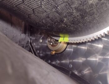
After a good deal of assessment and some test runs, I then bent the wire 90° and trimmed it just under 1.5″ long.  I welded a semicircular push-pull tab onto the wire and then primed and painted the tab.

I had to run out and pick up my friend’s daughter and take her back to her house, and also stopped by the grocery store for some stuff on the way back.  This gave the yellow paint a good bit to dry, and I carefully tested out the oil check door wire securing “latch” operation… I’m happy to report that it worked a treat!

With my oil check door wire securing “latch” operationally good, I then proceeded to tack weld a small safety tab in position to keep the wire from exiting too far out the aft end of the cowling into the prop.  Well, that was the goal of this task.

Between a slight rock of the welding table —which I remedied— and then having to work the TIG welder pedal while standing, I had an issue with the pedal snagging up on the table crossbar as I was cycling the pedal up and down during my welding.  Although I wasn’t getting a good burst on the tack weld, after a couple of cycles the metal was warmed up.  Then the pedal final came off its crossbar snag, let loose, and went “full throttle” on the warm wire —blasting it in half.

I then spent a good 15 minutes of improvisational welding to get the wire set back into position… resulting in ugly but hopefully strong welds to secure it back in position!  What a PITA!

Here’s my final <ugly> safety tab/GLOB weld on the oil check door securing wire.

Now, over the past week I’ve been pondering how to secure the aft end bent push-pull wire to the inside of the top cowling as both a safety measure so that it doesn’t work its way aft (or release the oil check door), and to keep down on vibrational chatter on the side of the cowl.

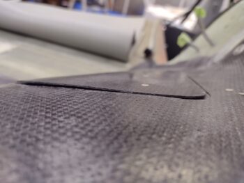
I decided to go with a simple clip that the wire snaps into when the oil check door is secured closed.  That resulted in an assessment on whether that clip should be metal or composite.  I landed on simply laying up 3 plies of carbon fiber to create a securing clip (think tape measure belt clip) on the inside side wall of the top cowling.

Here’s that layup with a taped metal block to keep the carbon fiber pressed down to the underlying mold.

As you can see, I laid up the carbon fiber (using hi-temp HTR-212 epoxy) and then peel plied the layup.

I also hit the yellow tab with a couple more coats using a brush.  I then left the layup and paint to cure overnight.

Tomorrow I’m attending an event with Jess that will eat up most of the day, and then after that my week should open up to get more stuff done! (hopefully).

Chapter 23 – Prop spinner dialed-in

I started out today by spending a bit of time straightening and angling the flat piece of the hinge that mounts to the oil check door (part with rivet holes).  The hinge gap on this flat piece towards the aft end of the door was a bit more than the front side, which was pretty much pressed firmly against the door.  Again, since the hinge is aluminum getting mounted to carbon fiber, I needed a buffer piece of BID in between to keep any galvanic corrosion from occurring over time.

So I simple added a couple of BID plies and stepped them so that they were thicker on the aft end, at the very slight gap betwixt door hinge and door (I actually added a triangular filler ply of BID, so officially 4 plies at the very aft end).  After wetting out the BID, I then slathered on some as-wet-as-feasible flox and floxed the hinge back onto the oil check door.  I’ll note that the hinge spring is in place, and since the door wire catch was in place as well as the door being firmly taped closed with Gorilla duct tape… installing that spring was no small feat!

I let the epoxy/flox cure for about 30 minutes as I cleaned up the excess oozing flox from around the flat hinge piece edges.  With the hinge refloxed to the door, I mounted the top cowl with all the CAMLOCS and screws installed and again placed weights on the oil check door to keep it as tightly pressed to the top cowling as possible.  I then left it to cure.

I spent the next couple of hours slowly dialing in the fit of the prop spinner by carefully removing any material that kept it from seating on the flow guide properly, or didn’t allow enough clearance with the respective prop blades.

Once the prop spinner prop blade opening clearances were good, I got to work on the front-of-blade gap filler pieces.  I had assumed (yes, we all know what “assume” means!) improperly that my buddy Dave Berenholtz would be using a Silver Bullet, and/or never gave it any serious thought.  The bottom line is while he has the same prop spinner, his prop configuration is such that the gap filler piece is much narrower than mine.

Since I based my dimensions off of his, my resulting 9-ply gap filler piece stock layup ended up being too narrow and too tall overall.  It should have been about an inch less in height and about 2.5″ wider.  Nonetheless, I could clearly get at least one of the  front-of-blade gap filler pieces out of it, so after finalizing the template I marked up the first one (pic 1) and cut it out (pic 2).

The longer side of this gap filler piece (lower in pic below) did not work out well on the first side, and with the overall opening just a hair narrower (about 0.050″) on the other side, I transferred the #1 gap filler piece above to the other side (#2) and fitted it into place.

Now, although the spinner curves a bit more as it departs the junction with the flow guide, I decided to check out how the other front-of-blade gap filler piece would turn out by simply cutting it out of my 9-ply stock… only in reverse to keep it as close to the front side of the stock as possible.  Thus, I marked up the second (new #1) prop gap filler piece.

And cut it out and fitted it into place.  Not perfect, but not bad.  Which is the exact descriptor that I will offer up for this entire prop spinner install effort.

Here we have the prop spinner installed, with the prop blade openings cut with good (or too good… read on) clearances.

And the requisite direct aft pic.  With the top cowl mounted this shot shows the actual clearance between top cowl and prop spinner flow guide: again, 3/8″.

Hindsight is always 20/20, and knowing the results now I would have approached the final prop spinner fitting a bit differently, focusing all the trimming on the right side of the blade in the first pic below.  Let me explain: with the screws installed, I would have then shifted the entire prop spinner counterclockwise to close up the slightly wider gap on the right side of the blade.  No, it won’t break the bank, but it is slightly wider than I desired. Pic 2 is a shot of the other side.

That being said, for some reason the 4 pre-installed mounting screw positions are all #6 screws, while included in the kit were #8 screws and platenuts.  Since I’ll be swapping out the #6 screws for #8 prop spinner mounting screws I plan to bias the holes CCW by about 0.02-0.03″ to balance out the clearance gaps around both prop blades.

Now, THAT all being said, here we have a wider angle shot of today’s activities: newly reset oil check door (hopefully comes out set as it should be on the cowling!) and installed prop spinner!

Tomorrow I’ve got a morning phone call with a good friend of mine, rolling into taking my little buddy to a county fair, and ending with an evening out with Jess…. so no more than checking the oil check door cure is in cards I imagine.  Sunday I’ll again be playing chauffeur to my little buddy for a round trip to her friends’ house (reminder: her mother had foot surgery and can’t drive).  So another somewhat impacted build day.

Nonetheless, pressing forward!

Chapter 23 – Prop spinner mounted

It’s been a slow couple of build days and I’m hoping to get some more solid work time in the shop, albeit more social events coming this weekend and Monday (sigh).

I was able to get a rather intricate task knocked out in the cutting of the prop blade notches in the Catto carbon fiber prop spinner.

I started by aligning the prop blade notch template with 2 of the 4 screw holes that are currently installed on the prop spinner and flow guide… the screws visible on each lower, outer edge in the pic below.  With my cut line known, I then placed green painters tape under the cut outline of the template to draw my cut line.

Here we have the cut line marked on the prop spinner, again spaced on 2 of the 4 pre-existing screw mounting holes (pic 1).  I then used the Fein saw to cut out the first of two prop blade cutouts for my Hertzler Silver Bullet prop (pic 2).

It took a good 45 minutes (yes, that long!) of measuring and aligning the second prop blade cutout in relation to the first, while simultaneously keeping it “centered” and aligned with the last 2 of 4 pre-existing screw mounting holes.

When I finally took the plunge, uh, literally, with my Fein saw to cut out the second and final prop blade cutout/notch, I had my fingers crossed (and a quick prayer) that my measurements were right.  Yep, measure 17 times and cut once . . . and Voila!

I was fully aware that my prop blade notches would most likely be tighter than they will be in final configuration, but better to remove material on final fitting than having to add eh?!

Moreover, I’ll note that in all these gratuitous installed prop spinner pics that the top cowling is NOT mounted in any way, and is merely loosely placed in position.

Here’s one more side shot to provide a general idea of how the prop spinner will look once finally installed.

Ok, tomorrow I am planning to get some good progress on both prop spinner final configuration AND oil check door hinge-to-door reattachment.

Limping along….

Chapter 23 – Finalizing bling!

I started out today by pulling the weights off the freshly floxed in place oil check door securing tube on the inside/underside of the door.  Thankfully when I pulled the weights off the door, it stayed in place… nice ‘n flush with the surrounding top cowl surface.

I pulled the wire out from the securing tubes and pulled the oil check door off the cowling.  Yeah, it’s not pretty, but it seems to be in the right spot to keep the door shut tightly into/onto the top cowling.

I mixed up some more epoxy, added some flox in a few key areas around the tube and then filled the remaining bigger gaps with dry micro.  I cut and laid up 2 plies of carbon fiber across the tube and peel plied the layup.  I set it aside to cure overnight.

I grabbed the molds I made of the forward side of the prop spinner to specifically use them as templates for cutting out the prop notches in the real spinner.  Using my cardboard template I transferred the notch opening to the first spinner template (pic 1) and then cut the notch (pic 2).  I’ll note, and as you can see, the templates are in 2 separate halves.

I then set the template in place around the prop blade and taped it to the flow guide.

I spent nearly 2 hours slowly dialing in the prop notch opening on this spinner template.  As I suspected, transferring the opening from a flat, albeit curved, cardboard template to this template with all kinds of curves going on made for some required adjustments (thus the green tape for back filling the edge).

Getting closer… (It’s an iterative process!)

Once I got pretty darn close on the first half template, I took about 20 minutes measuring the outer diameter to get as close to 180° out on the second template as possible.  I then marked up the second template and cut it out as well.

I noted these templates are of the OUTER surface of the prop spinner, so while they are great for getting the general shape and spacing of the prop blade notches configured, they are not exactly the size required.  In short, I’ll be cutting the notches on the actual prop spinner a little smaller and then work through the process of widening those out in situ around the prop blades.

Overall not a bad outing, although it took way longer than I thought it would to dial in these prop blade notches.  It was getting late and I wanted to hit it fresh again tomorrow as I hope to take the plunge and get the actual prop spinner notched and installed.

That being said, I got a request from my friend to take her to an appointment tomorrow down in Wilmington.  This is going to wipe out the majority of my shop time tomorrow, but I’ll do what I can.

Pressing forward… or trying to at least.

Chapter 23 – Oil check door redo

I had another social event that kept me out of the shop for nearly half the day, but I was still able to get some stuff knocked out.

First off, the top cowling’s oil check door has been a gnawing issue since after I set the door in place and attached it to the hinge.  The hinge construction gives it very little flex, and with the door having compound curves, attaching it to the hinge assembly greatly disrupted the door’s contour and how it flowed with the surface of the cowling.

Over the past few days I’ve been assessing and resetting how the door is secured to the cowling, but those are just symptoms —albeit important— but the core of the issue was the door-to-hinge attachment.  I had to remedy that to remedy any further oil check door fitting issues.

So I drilled out all the rivets and hit the hinge assemble with the heat gun enough to allow me to pry the hinge off the door.  I then heated up the door a bit and flexed it back into its original position, which it seemed amenable to.

I then put the oil check door back into position on the top cowling, weighed it down (note the aft inboard corner specifically getting weighed down as well) and heated it up a good bit with the heat gun.

I then took my friend’s daughter out for a late lunch and went to an arcade for about 4 hours.

Upon my return I removed the weights off the oil check door and was pleased to see that it was pretty much back to original shape and configuration… as in NOT all wonky in relation to the upper cowling.

After some more checks I realized that even though I had reset the forward and aft securing wire tubes attached to the top cowling, now the door was a little proud due to the door’s attached crosstube.  In short, something had to give and I figured I would attack the one remaining tube and get this oil check door snugged up tight —on the outboard side at least— in its position on the cowling.

With my Fein saw and Dremel tool I proceeded to remove nearly all of the cross tube attached on the underside of the oil check door.  I confirmed that the forward tube alignment was good and snug, it was just the aft side causing the door to sit a little proud, or high.

Now, I took a bit of gamble here in that I was working in the blind on resetting the door’s cross tube in place with flox.  Yet another reason I kept the front side attached.  I greased up the securing wire and added flox to the door’s cross tube before setting it in place and running the wire through all the securing tubes.  This has the door secured in its position [sans hinge] with the door cross tube floxed into position.  Then, to ensure the door tube cures with the oil check door as tightly in position as possible to the cowling, I weighed down the door again… and also that aft inboard corner as well.

I then left the door to cure overnight.

My goal for today was to get the prop spinner cut for the prop blades and have it on the bird, but that didn’t happen.  I did lay the groundwork though by getting a good start on creating the blade cutout template, with this being my first attempt.

I then refined my prop spinner blade hole cutout template with version #2.  Here I actually have the cutout configured to allow the spinner to get mounted around the prop blades.  Since I had taped thin cardboard to the prop blades to protect them during this process, I needed to get the clearance gaps pretty tight up next to the taped blade surface…

Which I was better able to do with template version #3.  It was getting quite late in the evening, and tomorrow I’ll pull the cardboard from the prop blades and simply use only tape before doing my final template version.

This shot of the prop spinner cutout template version #3 also provides a good shot of the “razor” trimmed 3-ply carbon fiber layup that I just completed, and the top cowl aft edge sanding that it allowed me to do.  Except for a few small spots, I’m back to 3/8″ clearance between spinner flow guide and cowling.

My final task of the evening was making up a template for the front-of-prop-blade gap filler piece that will cover that exposed area.   Here’s version #1.

Followed by version #2, which offers a bit more coverage of the gap.  I’m sure there’s a few more versions of these templates before I take the ‘knife’ to the prop spinner.

But it was late, so I called it a night.

Pressing forward!

Chapter 23/25 – More oil check door

I got a late start today having returned from Wilmington mid-afternoon and then having to give my friend’s daughter a ride to some of her friends’ house.

But I did get another round of tweaking the top cowl oil check door in… by getting the aft door securing wire tube marked (pic 1) and then cut out (pic 2).

With the door set back as firmly closed as possible, and secured in place with Gorilla duct tape (no spring!) I then proceeded to reset the wire-securing brass tube in place with flox.  I then covered that all up with 2 plies of carbon fiber, and peel plied the layup.

The clamp is to keep the wire pressed down against the inside top of the cowling, as I have the wire reversed and inserted just enough to keep the door configuration set.

I had cut out 3 plies of carbon fiber a couple of days ago in my assessing how to get as much clearance as possible with my current top cowling-to-prop spinner configuration.

At this point, the only options I really have left is a radical top cowl backend rebuild, or a more finessed approach of adding a few plies on top to then remove a few plies on the bottom… or actuality simply sanding the inside edge at a beveled angle to remove a good 0.06-0.08″ of cowling edge to keep it away from my prop spinner.  That should get me back to about a 0.36″ gap… which is about as good as I’m going to squeeze out of this setup.

In my quest to continually add more weight to this bird, I also addressed the meeting point (AKA “firewall”) of the sharp colliding angles of the canopy/D-deck on the forward side (left in pic below) and the aft flange that is aligned with the flow of the top cowl. It’s not too bad on the right, but on the left side I have a decent little dip, or trench, that I don’t want to simply trowel in a thick trough of micro.  I decided a judicious application of glass here would be good to fill the trough a bit, then allow the micro to be used in its clean-up role.

Here’s the firewall-located dip on the turtledeck:

I grabbed a small length of 3″ wide UNI spar cap tape, cut off 6″ long by about half the width of the tape (1.5″).  I then split that into thirds and cut 1/3 to to 4.5″ long and the last 1/3 to 3″ long (sorry, I should have grabbed a pic).  I pre-pregged the UNI so that ALL the ends started at one side [thick at bottom, narrow at top] and then wet it out.  In addition, I cut a single ply of BID about 6.7″ long x 1.5″ wide to cover the UNI.

Once the UNI strands were wet out, I laid them up in the trough, got them oriented and smoothed out fairly even, then covered them with the 1 ply of BID.  I then peel plied the layup.

I was trying to get to work on the prop spinner to get it cut to allow mounting over the prop and secured to the flow guide.  I was able to get the prop taped up to protect it as I shape the prop spinner, with the upcoming requisite on & off iterations.  But alas, I ran out of time since I needed to go pick up my friend’s daughter and take her back home, and then run to Jess’s place for dinner.

I added this shot above not just to display my masterful tape job, but also if you look on the top right of the prop hub you’ll see a bit of a delam.  The bottom left looks about the same.  There was a minor one on the top left that I hit with some epoxy and peel plied it, then tape.  This was after I sent these pics to Gary Hertzler, in requesting his advice on how to remedy these delams.  He responded that I should simply use epoxy under the delam (as pretty much any other delam) and keep it closed up during cure.

So I loaded up my delam/air bubble syringe with white vinegar and once cleaned out, I’ll attack these delams after I get the prop spinner configured.

Chapter 23 – Oil check door dial in

I finally got a decent chunk of stuff done today, and of course getting a bit of progress under my belt is motivating in getting this bird done!

That being said, my first quick task was to create a plan for dealing with the gaps I have in the front corners of the top cowling where the cowling itself fails to cover the gap between the wing edge and the cowling mounting/CAMLOC flange of the CS spar: the approximate 2.5″ along the outboard edge just aft of the corner, again on each side.  Now, I could fill this gap line with RTV once the wings are on the bird, but I want a more permanent seal and a better look than that.  Yes, this task is a bit cosmetic in nature here, but it also clearly concerns minimizing the loss of any engine cooling air.

Thus, my plan is to take away a bit of the cowl mounting flange and add that flange piece to the wing edge, extending the wing flange forward along that edge, but only around 0.3-0.4″ in width.  A bit hard to explain, but more to come on this.

On the oil check door configuration, I realized that it was NOT just the aft top cowl attach point that needed repositioned, but also the forward one as well (bottom of pic).  So I marked it up and took it outside to cut it out for resetting…

which I did here.

I then installed the top cowl oil check door without the hinge spring, taped the door tightly in place, and then set the door-securing wire in place.  I then added a dab of grease in the forward brass wire capture tube and slid it into place before adding flox all around it.

I then laid up 2 plies of carbon fiber over the reset oil check door wire-securing tube.  And peel plied the layup of course.

Before I mixed up the MGS 335 epoxy with fast hardener for all that going on above, I cut out 3 plies of BID to help fill in a right side gap on the front top cowling attach lip on the D-deck.  After laying that up I peel plied it as well.

I then carefully mounted my Hertzler Silver Bullet prop onto the bird to not only allow for cutting and installing the prop spinner, but to also ensure I had it configured with the blades at the 12/6 o’clock positions with the #1 cylinder at TDC.

My ignorance of how exactly to find TDC for the #1 cylinder came to light when I lined up the “TC1” line on the AFT side of the flywheel with the engine case split line.  “Uh, Houston we have a problem!” and “Strange things are afoot at the Circle K!” both came to mind since looking through the top spark plug hole proved that the #1 cylinder was anything BUT at TDC.

After some research I discovered by way of my RV friends on the VANs forum that I was in fact looking for the “TC1” line on the FRONT side of the flywheel, which brought the prop blades to exactly 12/6 o’clock with the #1 cylinder at TDC . . .

And put the AFT side flywheel “TC1” mark near the starter, which is what that mark is used for… ok, now we’re cooking with real butter!

Although the prop will be installed temporarily for only a bit, I also took the opportunity to check the blade alignment as is spelled out in the plans.  With blade #1 down, I made a mark on some green painters tape just below it, then rotated blade #1 up and blade #2 down in position.  Here is the result: well within the 1/16″ difference allowed by the Long-EZ engine plans.

Since I used fast hardener, I pulled the peel ply off to check the forward wire-securing tube for the top cowl oil check door.

I also pulled the peel ply, razor-trimmed the cured overhanging BID and re-drilled the CAMLOC hole for the right side D-deck top cowl mounting flange.

I would say tomorrow I’ll get back on the top cowl and prop, but I’m leaving tomorrow morning for a quick overnight trip to Wilmington, NC for a little R&R with Jess.  I’ll be back Sunday midday and will get back to work then.

Chapter 23/25 – Top cowl fit bits

The last couple of days have turned into pure assessment and planning days… not so much that I had planned to do so, but a friend of mine had surgery on her foot and I’ve been playing chauffeur to her teenage daughter (who I’ve known for the majority of her life).  That’s affected my build schedule significantly over the past week.

I finally got a few good undisturbed hours out in the shop, where I started sanding down the layups I just did on the front top cowl CAMLOC tabs.  An unintended consequence of adding thickness to those tabs is driving the aft end of the cowl downward much more significantly than I would have thought.  My gap now between aft cowl edge and the prop spinner flow guide (“lampshade”) went from about 0.36″ to about 0.295″, in 3 distinct spots: 12:00 (TDC), 9:30 (L), and 2:30 (R) clock positions.  5/16″ is my minimum allowable clearance between prop spinner and cowling.

I’m assessing the mitigation of that gap, but will wait until I get the remainder of the top cowl front interface with the D-deck dialed in to take any further action.  I have a couple of tricks still left in my bag to deal with it.  In the meantime, as I often do, I’ll probably go ahead, accept the risk and install the prop… since I’ve come this far on getting that prop spinner worked into the mix of my cowling configuration, and as far as I’m concerned, the damn thing is getting installed on this bird!

So the top cowl went on and off a number of times.  I’ll note that there is just a hair more of finagling to get it on now since I finalized the wing positioning (a good while back) with extra washers on the left side.  I may drill out a couple of stationary CAMLOC receptacles to replace them with floating ones to see if that eases the finagling of the top cowl going on: the culprits being the 3 CAMLOCs along the lower left front edge.

So I’ve been slowly working my elevations between D-deck and top cowl front lip, and I finally removed a high point that I had identified and marked long ago (the hash lines).

I grabbed my Dremel tool and mini-sanding drum and went to town on the offending protrusion, then a good bit of elbow grease with a 32-grit sanding block.  Now along this this 3″ section the interface between cowl and D-deck are at the same elevation.

Then another few rounds of top cowl on & off to assess the oil level check door fit into and onto the top cowl.  I removed a small bit of baffle seal material that was getting in the way of the oil check door hinge and finally went a few rounds of bending the hinge on the underside of the door using 2 big channel lock pliers and stir sticks to protect the door & hinge surfaces.

I also secured the door with my “remote” opening wire to see how the elevation looks, and concluded that the aft most attach point on the inside of the cowl must be removed and reattached to get the door to sit more tightly against the inner flange.  The area I’m discussing is the on the left side in the pic below.

Now, although I bent the hinge where it attaches to the underside of the door, it only really affected the outer edges (aka front and aft side… since it opens inboard) of the hinge.  The middle is still relatively flat.  With the hinge attach point being a good inch from the edge (note rivets), this results in the front and aft inboard corners still protruding out rather straight… while the top cowling surface curves a good bit in this area (right side in pic below).

My plan is to simply add plies of carbon fiber to the underside of these corners to “fill the gap” between corner and cowling, and then simply sand down the tops of the corners to match the top cowl surface.  I’ll end my discussion by noting that this is a result of attaching a flat hinge (~5″ long) to two different interfacing surfaces (cowl & door) on a compound curved surface.  So I’m dealing with it!

Yes, with my refined plans in hand I will get to it… tomorrow.

Pressing forward.

Chapter 21/23 – Dialing in top cowl

Ok, again, a lot of smallish tasks getting knocked out over the last couple of days.

First off, I measured the gap between the top centerline CAMLOC position on the front edge of the top cowl with the D-deck to be about 0.085″ thick.  When I pulled the top cowling off to work the top centerline CAMLOC attach flange thickening, I forgot that the cowl hadn’t been off since I created the aft cowl stiffener.

So I pulled the peel ply and cleaned up a couple rough spots on the layup.

Here’s a closer look at the cured top cowl aft stiffener.

My hypothesis on the D-deck CAMLOC flange for the top cowling is that somewhere during the cure cycle (way back when) it drooped a bit from about the 10:30-2:00 o’clock positions, considering I have a gap between the flange and the 5 ply perimeter layup (see pic below this one).

The resulting gap, as I mentioned above, between the top centerline CAMLOC mounting hole and the inside surface of the top cowling is around 0.085″.  To fill in all but 2 plies of BID worth, I’m using a small patch of 1/16″ (0.063″) G10, with the front edge beveled to slide forward into that D-deck-CAMLOC flange gap… as seen below.

After getting the G10 filler piece drilled (1/2″ hole), sanded and prepped, I then floxed it into place.  I used a taped 1/2″ OD tube and a clamp to keep the G10 firmly in place during cure. Now, if you look in front (left in pic) of the added G10 piece, you can see the light area where I first packed in flox into the separated layers of glass.

And another shot of all that, after the flox cured and the G10 pad was secured in place.

After sanding and prepping the cured, in-place G10, I then added a micro fillet around the G10 filler piece (micro for weight) and laid up 2 plies of BID.  I then peel plied the BID.

Obviously this pic is a bit later after the peel ply was pulled and the edges razor trimmed.

I started out Day 2 with a similar operation, only using stepped, pyramiding 3 plies of BID to fill in the area above the top left CAMLOC on the D-deck and peel plied the layup (pic 1).  I used MGS 335 with fast hardener on these filler layups, so a few hours later I pulled the peel ply and razor trimmed the layup (pic 2).

After the layup above, I then took the final half of the wheel pants outside and sanded it in prep for micro and final finishing.  Yes, this is lower priority, low hanging fruit stuff, but I want some of these small tasks that take 30 minutes or less off the to-do list to knock it down a bit.  It’s part of my mental game to stay motivated I guess.

I combined these pics below although I started the task yesterday by applying the first round of insulation to the fuel injection spider stainless steel distribution lines that go to each cylinder.

Today I finished the task with the second, final outer insulation layer on the stainless steel fuel distribution lines. Technically, the task will be officially finished after I receive some Tefzel zip-ties that I ordered from Stein Air, albeit the hard part is definitely over (this was not just a simple, quick feat of adding these insulating sleeves).

As per Cozy builder/driver Buly, he used -4 fire sleeve on his topside fuel injection distribution lines to keep them from heating up too much when needing to do a hot start (which is the main risk of having the fuel injection spider lines on the top of the motor in our cooling configuration).

Again, I’m using a double-layered approach using insulating sleeves from McMaster-Carr (see pic below).  The first layer is heat-reflective wrap around sleeving, “made of aluminum with a fiberglass liner [which] reflects heat away from contents and withstands temperatures up to 390° F to protect against internal and external heat sources. It resists chemicals and fluids. The slit along the entire length permanently seals with an adhesive strip. It meets ASTM D350 requirements for self-extinguishing material.”  The outer, more durable layer is a heat-reflective slit corrugated sleeving that “reflects heat away from contents and withstands temperatures up to 300° F to protect against internal and external sources of heat.”  Moreover, I’m securing these sleeves in place with Tefzel zip-ties, which are quite capable of handling engine compartment temperatures.

I finished the evening out by making a video with a new (to me) but a little older (like me!) Akaso action camera that I nabbed for pretty darn cheap off of Ebay.  I figured I would put it to the test by using this tiny camera to record this video on my current gas cap safety lanyard effort.  Admittedly, the internal mic on this video camera isn’t that great, but after editing & processing it’s passible.

I’m getting close to finishing up a couple more key tasks, getting the shop cleaned and organized, and then a big project update video before I press forward with my top side micro finishing of the bird.

Moving forward!

Chapter 23/24/25 – More tidbits

Yep, my prevailing trend of not getting nearly as much done as I want to in the shop has continued over the past couple of days.

I did get a good 45 minutes of sanding on the wheel pants in, with 3 of the 4 halves ready for micro-finishing (no pic of those).

I also continued on with my sideline tasks before I get back onto the upper cowling final tweaks I need to do (more on that in a bit).

I pulled the prop spinner side gap filler pieces blank off the spinner, pulled the peel ply and cleaned up the edges.  Now when it comes time to create the filler pieces, I’ll have the blank ready to create those with.

In addition, I pulled the GIB lower seat hole cover off its layup board, measured out 8.5″ diameter and cut that before sanding the edges smooth.

I then did a quick check of it in place, which it fit a treat… Voila!  I’ll add a few spots of Velcro around the perimeter to attach it and then call it done and good.

I did note that the squirrels attacked yet another light.  They are quite clever in gnawing away the cord with very little left to splice back onto.  I disassembled the light end, pulled some more cord out so I had some wire to work with, and in about 15 minutes I had the 2 inop lights back up and running.

I also spent a good little bit of time using the Dremel tool and files to trim and clean up the edges of the gas cap tether securing tabs.  Again, these are 0.036″ thick 316 stainless steel.  After cleaning them up, I then bent the tabs 90° in prep for mounting them to the bottom of the gas caps, respectively.

I also spent some time determining my filler and layup plan for the top dead center CAMLOC position on the top cowling, since the current gap (0.085″) between CAMLOC tab and top cowling results in the cowling getting pulled down too much and the outer edges bulging a bit.

My sequence in dialing in the top cowling was to get the aft stiffener in place first, then work each minor issue from there.  This will be the first of a few final alignment tweaks between cowling and its fuselage-side mounting flanges.

Due to Jess’s busy schedule, and some medical stuff going on with her grandmother, I wanted to treat her to a nice dinner tonight… so the top cowl top position will get worked tomorrow.

Still inching forward!