Chapter 25 – Blue bottom cowling

Today I pulled all the protective tape, plastic and paper off the bottom cowl to reveal the black stripes.  I had some issues when I shot the sealer (which is exactly why I use it… it’s thin and highlights problem areas before final paint) which I mostly corrected before the paint coats, so I needed to be a bit more diligent in prepping the middle section for blue paint.

I first taped off the black stripes and outboard strips that will eventually be white.

I then shot a good bit of the bottom cowling middle area spots with hi-build 2K primer.  Some problem areas got 4 coats to ensure a smooth fill and transition after sanding.

Which I did next.

I let the 2K primer cure for its minimum 4 hours before DRY sanding it with 320 and 400 grit sandpaper.  This took a good majority of the 2K primer off the bottom cowl (sorry, no pics) with a lot of bare carbon fiber and micro showing through.

After a thorough cleaning/degreasing and another 30 minute minimum dry time for that, I shot a good coat of sealer on it to not only seal the unprimered spots, but also to check for any irregularities that would need to be attended to… thankfully there were none.

I then shot the middle area of the bottom cowling with the blue.

I’ll note that getting into the slotted gaps both inboard and above the air intakes, as well as inside them —with the air pressure and fluid volume turned way down and the spray patterned narrowed— still resulted in a bit too much paint… which interestingly caused a run on the AFT outside of the left air intake.  No biggie as most ALL the painted bits on this bird will get buffed out.

Other than that run, and mixing up a bit too much of this expensive paint in fears of running out mid-job, it turned out nicely.

More to follow… hoo-ah!

Chapter 25 – Bottom cowl black stripes

Yesterday I used the Icing to fill some divots and major scratches on the bottom cowling.  I then sanded those down and hit them with white primer, and then sanded that.

Today, to get the black accent stripes matching on the front side with the strake bottoms’ black stripes and with the aft top cowling black stripes, I mounted the bottom cowling onto the bird.

Then, for the first time since it’s been painted, I mounted the top cowling to again line up the black stripes with the bottom cowling.

I have to say, my color scheme is coming along as well, or better, than I expected! I’m very happy with it.

Here we have the aft side of the bird with the top cowling in place.

And a couple more side shots.

I then spent well over 2 hours getting the bottom cowling black accent stripes aligned, spaced, and flowing the way I wanted them… and taped up with fine line tape.

I then finished taping off both the center (with plastic) and the outboard stripes (with paper) to allow painting the black accent stripes.

Which I did next.  Here’s both the left (pic 1) and right (pic 2) bottom cowling black accent stripes painted.

If the weather holds tomorrow I plan on shooting the main center section of the bottom cowling blue.

Pressing forward!

Chapter 16/22 – Firewall components

Starting off, here we have the painted left wing with all the protective tape removed from the winglet, wing root, etc.  Also, note the Thermo-Tec heat shield applied inside the wing root.

Today was quite the busy day on the firewall and inside the hellhole.

I started by touching up the black paint on the aileron control rods, then permanently installed them onto the CS124 bracket.  In turn, I then installed the CS124 bracket into the firewall-attached bearing sleeve before bolting it to the internal control tube (inside hell hole) with an AN3 bolt as per plans.

With the aileron control system in place, I then installed the “Forest-of-Tabs” ground block inside the hell hole.  On the bottom of the this ground tab block is a 5/16″ brass thru-bolt that is the connecting post on the firewall for the engine grounding strap.

Additionally, in the stainless steel firewall pass-thru for the starter cable and alternator F-lead, I cut a a length of Nyla-flo to serve as a protective sleeve for the F-Lead.  You can see that the alternator cable has a black heat shrink anti-chafing sleeve around it.  Once the cables were protected from any chafing, I then filled up the gaps around the cable/wire inside the stainless steel pass-thru with gray hi-temp RTV.

I then slid a piece of orange fire sleeve over the stainless steel pass-thru extending out from the firewall, after I slathered up the inside with gray RTV.  I then added a Tefzel hi-temp zip tie (not in pic) to secure it even more.

I also connected the alternator B-lead inside the hell hole to the Blue Sea (red block) pass-thru.  While up inside the hell hole I snagged the leads to the GRT CS-01 Hall Effect amp sensor and pulled the sensor out of the donut.  It looks easily enough to repair, but I’ll have to check with GRT before proceeding.

Chapter 25 – Left wing painted!

Well, the weather actually held yesterday, and I got the left wing painted.  I waited until today to post it because I wanted to see if my hack worked to keep dew from forming on the wing top.

And it did.

My hack?  Pretty simple actually.  I just placed my 3 heat lamps under the wing to keep the surface temp above the dew point.  As you can see, it worked…

No dew on the left wing top and it stayed nice and shiny… (Although all the painted parts will get buffed out —planning/working on that task currently).

Clearly this is the last of the major big parts of the plane that needed painting, although the bottom cowling is next up on the docket and it’s got some decent surface area.

After I grabbed these shots of the wing, I took it off the 2×8 mount, placed it on the wing dolly and moved it into the shop.

Now, when I painted the right wing I also painted the outboard sides of the rudders.  In the last couple of days I painted the inboard sides of the rudders as well.  Unfortunately the inboard right rudder surface had visible pockmarks after the second coat.  I let it cure, sanded it and reshot the white paint this afternoon.  Although I didn’t grab a pic of it, it turned out much better than before and very acceptable.

Moving forward . . .

Chapter 24/25 – More stuff on wings

The temperature high for today was fine for painting the left wing, but the overnight low was just not acceptable for leaving the wing on its mount overnight.  I don’t want a repeat of the right wing dew shenanigans.

So I did some cleanup tasks on the right wing.

I started by first removing the protective Saran wrap plastic filling the insides of the outboard video camera mounts.  I then taped up the holes and gently drilled them out to accept a 10-32 screw.

Here they are after cleaned out and prepped for use (note the tape on the edge of the leading edge light opening… I had a few white paint touchups I had to do from the tape pulling small bits of paint off).

Near the strake junction on the top right wing I did the same thing for the top two baggage pod mounting holes.  The inboard hole however had some gunk (epoxy?) in it and I had to employ a 10-32 tap to clean it out.

A somewhat blurry pic showing the top baggage pod mounting holes cleaned out and ready for use.

Since I’m not painting until tomorrow, I then did something that some may call controversial.  Ever since I discovered this concept I have really wanted the capability to mount a 360 camera on a pole that will take pics/video in flight that looks like the plane has its own linked drone flying just out in front with nothing showing (it removes the pole in the picture/video editing) but air.

I’ve pondered this for a good while, and made chicken scratching sketches on how I’d do it, but I set that aside for the future since I wanted to get this bird in the air ASAP.  But with a known day and a half weather delay before painting, I decided what the hell… let’s dive in and get it done.

Below is actually from late afternoon yesterday, when I positioned a 1/2″ pole aligned with the aircraft centerline at about 1-2° nose down (since the plane flies 2° nose up).  I then drilled the 6 each 3/8″ holes for the aluminum threaded inserts I made on the lathe late last year (yes, specifically for this mod).  The bottom 3 are all into the lower winglet.  The middle and aft on the underside are actually into the winglet intersection fairing.

The “controversial” part of this mod one could argue is the front underside hard point: it is mounted into the actually wing, along the same line as the hole many builders drill into the wing for a tiedown bolt.  Obviously being more outboard, my hole is into the UNI and BID layups that secure the winglet onto the wing… note that I drilled the hole more inboard so that nearly 2″ of layups are attached to the bottom wing before the insert hole.

My final decision to do this is based on an entry in the plans where it states that we are not to add more plies to the layups since the “winglet joint can withstand 90-degress sideslip flight at 170 mph – considerably over normal requirements.”  Thus, I figured stealing 3/8″ out of the strands, while still leaving a nearly 2″ overlap onto the bottom wing undisturbed —especially since I don’t plan on doing aerobatics in this bird— was wholly acceptable and not causing any safety issues… IMO.

I had removed the screws and popped off the taped wide area washers late last night in hopes it would allow me to scrape off any excess flox if still in the “green” (gummy) stage.  It was not.

So today I took the Dremel tool with a cutoff disc and carefully removed all the excess flox.  I had a couple of the aluminum inserts protruding out a hair, so I shaved those down as well.

I then slathered up the area around each insert with some Icing filling, and after it cured sanded it all down.

I then hit the area with higher quality rattle can white primer, which I’ll wet sand after cure along with the bottom of the wing.  Also, before final paint this area will get a coat of sealer.

Back on the right wing, I grabbed this shot to again show the dull interior paint on the wing top from dew, as compared to the shiny leading edge.

In the early evening I wet sanded the bottom of the left wing in prep for painting it.  Again, if the weather holds tomorrow, I will be painting the left wing white.

Rock ‘n roll!

Chapter 25 – Left wing paint prep

Today was all about getting the left wing prepped for paint.

I started off by taping up the blue and black accents on the winglet.

And then a final check for any divots using black paint as a guide coat.  I have to say this is a requirement for me since even though I’ve used the “poor man’s guide coat” using a pencil, somehow a few divots had weaseled their way through to final paint… the right top side of my canard is a perfect example as it has a couple small divots that I need to remedy.

Thus, WWII Luftwaffe camouflage looking paint it is on the top of the left wing….

I then wet sanded the top of the wing, with a couple of divots that needed Icing fill and sanding.  One of those divots being the delam repair I made on the inboard top near the BL 55.5 edge.

I then mounted the wing to my temporary 2×8 wing painting beam, facing the other way than the right wing of course.  And since the wings angle aft from what would be the CS spar, I spent a good little bit slowly pivoting the canopy cover over so that the wing would be in the center of it.

At this point the wing is ready to paint, but I may need to hold off a day or two for the weather to cooperate.

Pressing forward.

Chapter 25 – Right wing painted white

With my recent decision to paint the wings, I was back to figuring out just how to mount them prior to painting.  You see, unlike hitting the wings with primer, one side at a time, when it comes to painting it needs to be done all at once.  Although my painting skills, the weather and the environment rarely meet the quality of a skilled painter inside of a paint booth.

Some builders, like Shane Banquer, have made wing stands that they have shared pics of with me… both wings mounted with the leading edges either up or down, and on a roll around dolly.  Probably good if at an airport to roll them out of the hangar, paint them and then back in for cure.  But if I were to make one it would most likely be stationary… and I thought about doing that… but that’s a lot of work.

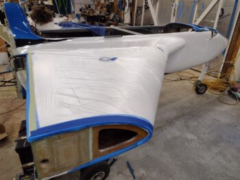
Seemed much easier to just mount the wing on the CS spar/strake, protect the strakes, gear, fuselage, nose . . .  see where I’m getting to.  After I started taping and covering everything up, I realized what a HUGE job (and PITA) it was going to be just to cover up everything on the strakes, fuselage, nose, etc. just to paint the wings.

After some pondering and a bit of measuring I decided to make a fairly quick wing painting mount that I could use for both wings, for about $20.

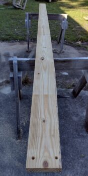
What would I need to buy?  Well, one 16-foot long 2×8.

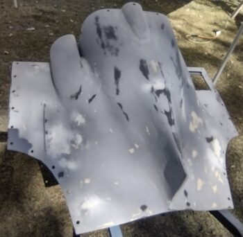
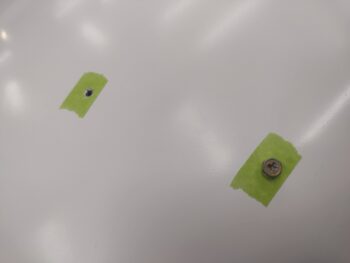
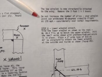
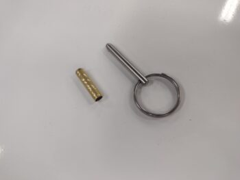
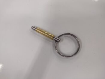
I then trimmed one end to match the wing/CS spar mating shape and determined where the bolt holes needed to go, and drilled those.

My mounting location for the my new temporary ‘centersection spar’ fill-in wasn’t perfect, being over grass and all, but at this point with the days getting shorter and weather getting colder daily, I need to get a move on it.

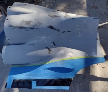
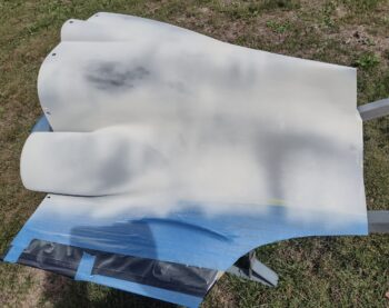
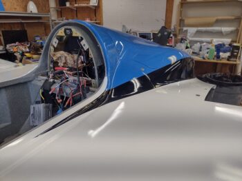
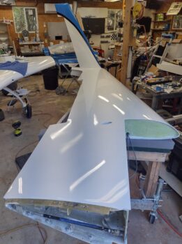
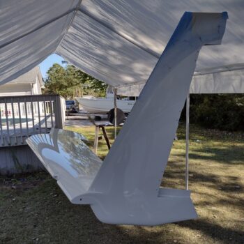
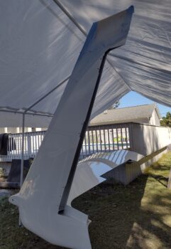
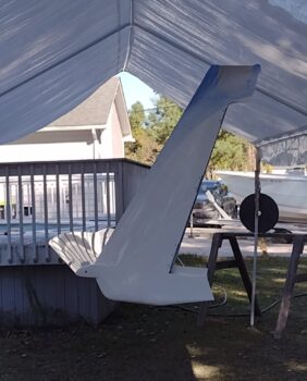
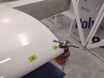
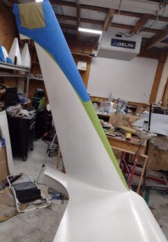
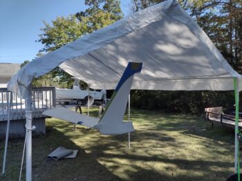
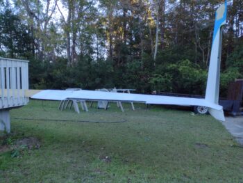
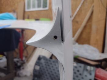
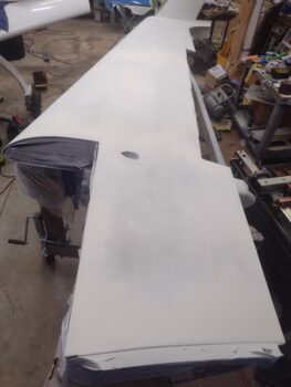
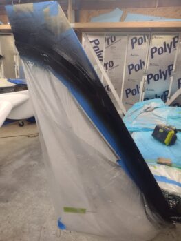
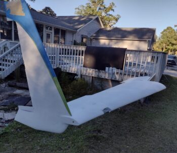
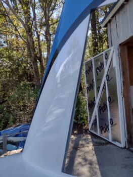
Here is the wing mounted to the 2×8, which in turn is mounted to my above ground pool deck railing….

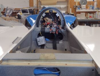
which you can see in these pics here,

and here.

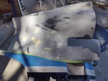
Clearly enough room for me to get up under the wing and paint it (note the blue and black winglet accent stripes taped up).

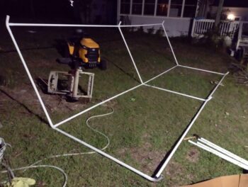
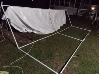
My late night operation was getting the 10′ x 20′ carport/canopy assembled to keep any moisture off the wing while it was curing.  I failed to get a pic of the finished canopy over the wing.

I started painting the wing the following day, and after wet sanding the underside, and cleaning/degreasing, final prep, and tape up, some spot shooting sealer coat, and two coats of white paint, I finished about 2:30 in the afternoon.  The weather temp was in the high 60’s during the afternoon and started cooling quickly by mid-evening.  The coldest forecasted temp was at 7am the following morning at 50° F.

Since this Nason paint can be shot anywhere above 50° F, I wasn’t worried about the temp, and I had the canopy over the wing for any moisture.

OR so I thought.

The paint turned out REALLY well.  I had a few bugs after the first round, that I extracted successfully.  And then maybe a few very small aphids after the second and final coat.  I didn’t have a super glossy coat (but acceptably shiny), and therefore NO runs, but it was a solid outing.

I left for Jess’s place a little after 11 pm and everything was looking good.  Temp was about 58° and the paint still looked very nice.

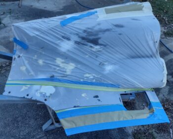
But I’ve realized something about our foam filled aircraft components: they attract moisture… dew to be exact.  While everything else in the vicinity can be bone dry, the wings outside will be wet with dew.  I mistakenly thought if I had the wing under a canopy, completely covered, with it having already cured for over 8 hours, that the paint would be fine.

I was wrong.

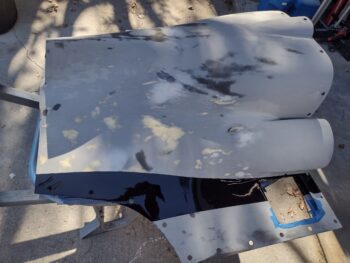
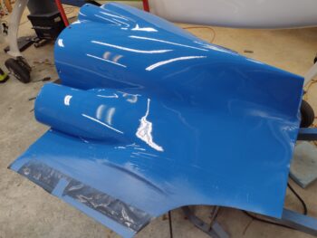
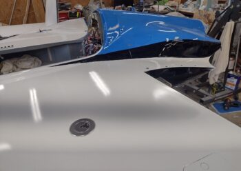
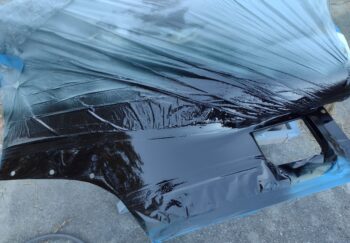
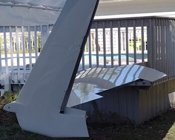
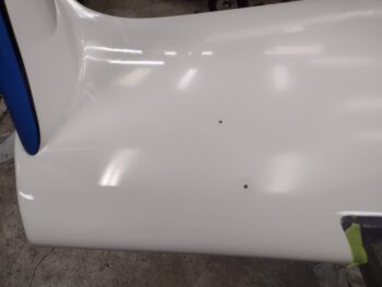
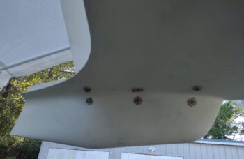
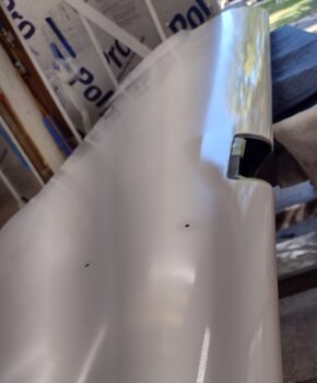
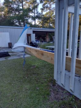
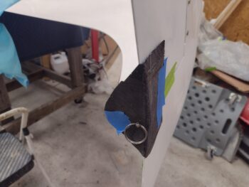
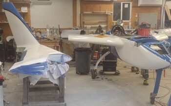
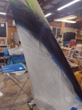
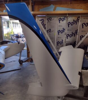
This shot of the inboard winglet is typical for how the rest of wing paint job looked when I left last night.

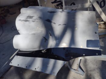
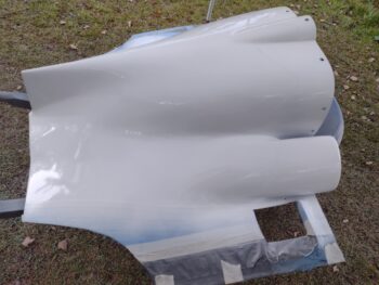
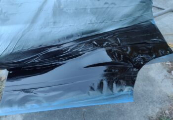
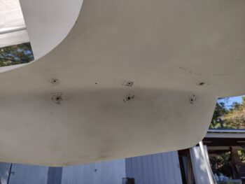
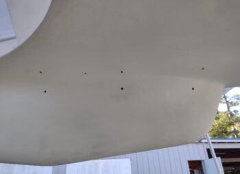
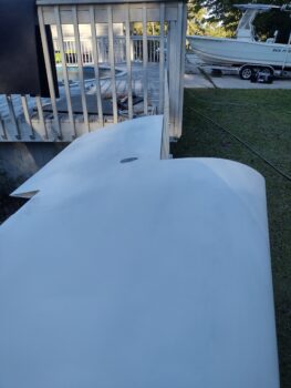
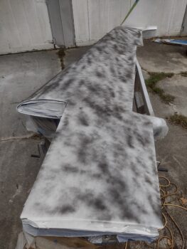
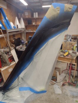
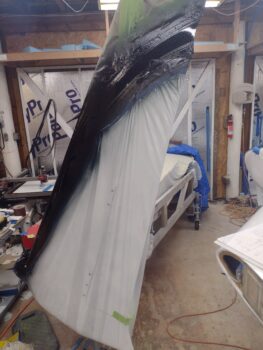
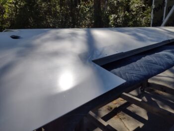
But when I arrived this morning, the center top section of the wing was covered in dew, a few inches in from all edges. It’s hard to tell by looking at the actual wing trailing edge on the left, so focus just forward of the aileron cutout center right of pic.  See how shiny it is along the edge?  And how dull it is in the center?  It still looks like it has a coat of dew on it, even though it’s completely dry.

In talking with the paint guy at NAPA he told me about a guy down the highway from them that is reportedly an export in buffing out just about any paint, including single stage.  With this latest fun fiasco, I will be giving him a call to see if he can bring this dull, dew-damaged center wing area paint (and every other spot) back to life: nice and shiny.

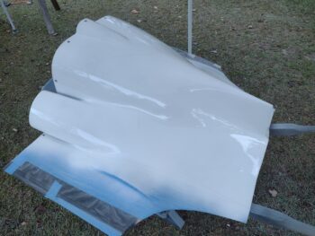
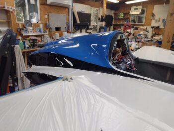
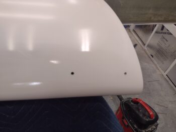
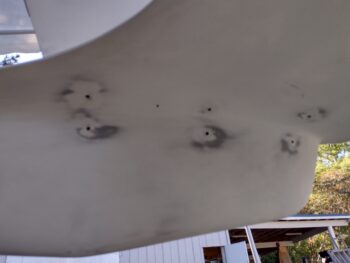
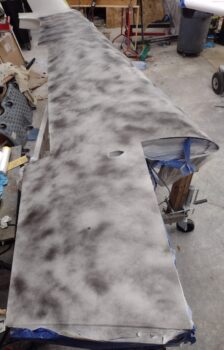
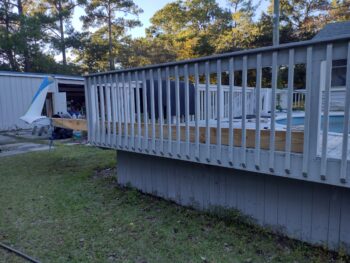
Regardless, here is a requisite shot of my painted wing.  I am happy that it’s done, but clearly my frustration factor of playing constant Johnny-F***-Around with all this paint stuff is high.

Anyhoo … still pressing forward, even with all the BS that keeps popping up!

Chapter 24/25 – Wing paint prep

Today I removed the tape, plastic and paper from the winglets to reveal the black accent stripes, here on the outboard of the left winglet (pic 1) and the inboard side of the right winglet (pic 2).

And the opposite in these pics below, with the inboard of the left winglet (pic 1) and the outboard side of the right winglet (pic 2).

I then got to work on placing and drilling the right rudder gust lock.  I placed the pin inside the hole for this pic.

I then prepped the brass securing pin sleeve (pic 1), and then a shot of the pin inserted into the sleeve (pic 2).

I then micro’d the sleeve into the just-drilled hole and left it to cure.

I then moved the right wing outside, and using a cheap can of black spray paint covered the top surface as a guide coat (pic 1).

I then did a few rounds of sanding, and after finishing I had a few depressions in the top wing surface… more than I of course would care to.

After some more prep, I then shot the depression areas with 3 coats of hi-build 2K primer.

I grabbed this shot just to show the winglet paint scheme in combo with the fuselage… not bad (smile).

And more of a “secret” project that I’ve been working for over a year… this is a non-GRT magnetometer that I’m assessing its mounting position in conjunction with the two GRT magnetometers.

I’m hoping the weather is good for the next day or two to allow me to paint the right wing.

Chapter 25 – Winglets ‘back’ in black

Today I was able to successfully get the black accent stripes on the winglets painted.

Here we have the right winglet black accent stripes painted . . .

And the left winglet’s.

On Marco’s trip to this year’s Rough River fly-in (I didn’t go in order to get this bird done ASAP) he tested out using the Starlink Mini system to have full-time/real-time Internet in flight primarily for optimized weather reports.  Obviously Marco needed to place the antenna somewhere, and for his implementation he settled on using the left strake baggage compartment.

To plan this capability, Marco created a CAD model to test out his deployment.  Thankfully he sent me the CAD file, which I was able to split up to print on my only operational 3D printer at the moment (too small to print it out in full).

When I get a chance I will assess where I can fit this antenna in my bird.  The left strake is a no-go for me since the outer skin is covered with a ply of carbon fiber, so I will look at other options.

Tomorrow I’ll pull the tape off the winglets and start prepping the wings for final white paint.

Chapter 13/22 – Final firewall install

I spent most of the day today prepping and working on finalizing the application of hi-temp RTV to the edges of the CS spar “outriggers” that are exposed to engine compartment heat . . .

And also around the adjacent edges of the titanium firewall and the lower firewall corners.

Of course I had to buy more hi-temp RTV, and since the gray was cheaper, nicer looking (IMO) and good up to 1400° F, I went with that.

Also, note on the upper firewall above that I have installed the ElectroAir coil pack, as well as terminated and installed the left side P9 power CPC connector.

Below we have the right side P10 data CPC connector terminated and installed as well.

Finally, after installing the P9 and P10 connectors, I then applied sound-deadening foam on the aft wall of the headrest/forward side of the firewall.

Tomorrow, if the weather holds, I plan on shooting the black accent stripes on the winglets.

Pressing forward!