Chapter 19/25 – Lending a hand

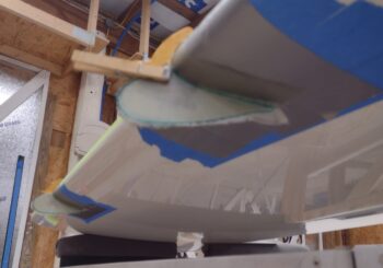
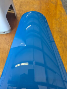
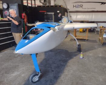
This morning I brought a small batch of blue paint to Phil’s shop to use on the blue paint breakthroughs around the nose hatch lip and some spots on the D-deck.  After some discussion with Phil, I ended up touching up the breakthroughs on the blue paint as Phil and Ray finished up ceramic coating the white painted surfaces.

I also cleaned up and reapplied blue paint on the bottom triangular strip that ends at the bottom forward tip of the nose.

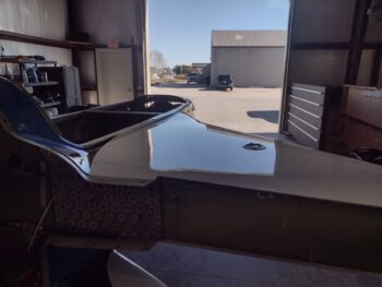
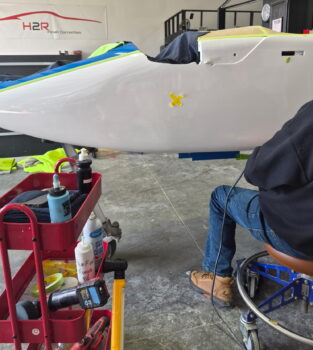
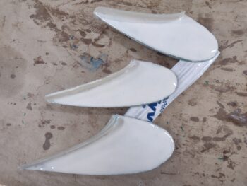
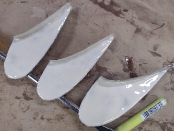
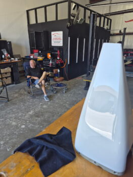
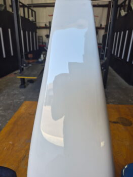
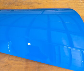
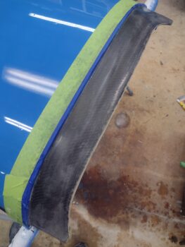
By the time I left, Phil and Ray were back to buffing out the individual parts I had left with them… here, the right rudder.

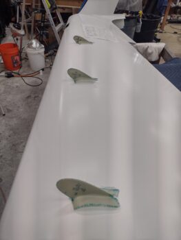
After returning to my shop, I sanded down the micro on the right vortilons to ready them for epoxy wiping, which I did next (2 coats, no pics).

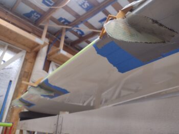
I also did a final clean on the leading edge light pockets on both wings, and with some left over epoxy from the vortilons above, epoxy wiped the light lens flanges and the interior carbon fiber.  This epoxy will get sanded later before the light lenses get RTV into place.

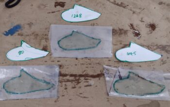
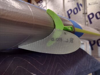
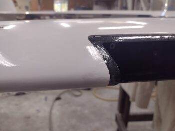
As I was working on the right wing —which I’m trying to finish up since it is next to get sanded and buffed— leading edge light compartment, I noticed that a strip of paint had been pulled up on the outboard edge.  I still had the strip of LE tape I used for glassing the vortilon flanges, to reuse, and sure enough found the paint remnants on the tape.

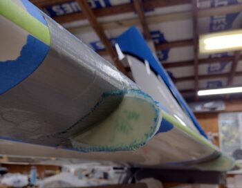
I then sanded down the damaged paint area on the leading edge, with some minor bit more paint chipping away during the process… better now and repaired than later on when it’s flying is my opinion.

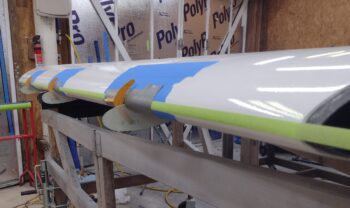
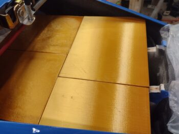
I then hit the sanded right wing leading edge paint damaged area with 2K sealer and let that flash before then applying 4 coats of white paint.

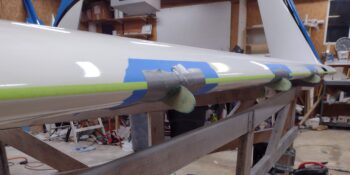
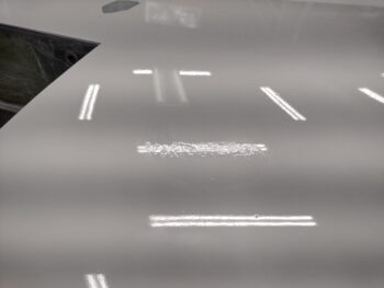
Since I was doing white paint repairs, I had about a 3″ crescent shaped area on the top of the left wing that had very visible pinholes, that just so happened to be right where I repaired the delam.  Apparently I failed to inspect it closely after shooting primer, and the pinholes came through the top paint.  I used a trick that Dave Berenholtz told me his painter did, which was use my finger to drive primer into pinholes to remove them.

Thus after wet sanding the area with 1200 grit, I then applied 2K sealer and used a razor blade and my fingers to fill the pinholes.  Once the sealer flashed, I then applied 4 coats of paint to cover the sanded areas and pinholes.  There was another spot on the inboard edge closer to the leading edge (just past lower left in pic) that had some distinct pinholes that I did the same thing.

This will all get very finely sanded by Phil and Ray before buffing out, so I expect this will be completely hidden by the finishing process and pinholes gone in the final product, or at a minimum be greatly minimized and only seen by very close scrutiny of the surface.

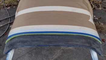
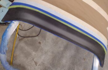
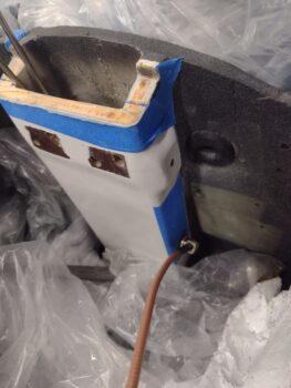
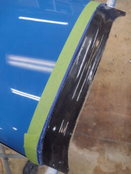
My last cleanup act of the evening was the black border around the blue on the very bottom edge of the left winglet (hard to get a good pic).  I very carefully scraped away white paint that had intruded under the tape on the black stripe, then taped off the white and dabbed some black paint on the stripe to clean it up.  Looks good and pressing forward.

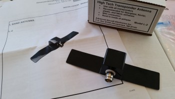
More vortilon work to follow….

Chapter 10/19/25 – Long-EZ parts done

I got a call from Phil to tell me that my fuselage had been buffed out.  The most significant squawks are a thin spot on the right strake leading edge and a minor breakthrough on the left sidewall where I had a nasty run.  This quarter-sized breakthrough sits right under the canard and will only be seen with the nose up and somewhat stationary.

We also had some cut-throughs on the very edge of the nose hatch perimeter lip and a few spots on the turtledeck.  If you remember, I had seriously thought about re-shooting the turtledeck and am kinda wishing I had now.

All the squawks aside, which are all due to my painting (and learned knowledge vs gain knowledge), the fuselage is looking great.  The biggest thing is how shiny and glossy the paint is now, especially the previously dull strake tops that had dew damage.  As you can see in the pic below, Phil and Raymond did some magic on those strake tops.

[Added pics]  I got these pics a few days after I made this post, so a bunch more shots of the bird in Phil’s shop.

Phil buffing out the left side.

Left side nose.

Some more left side in progress:

Right side . . .

Blue center strip is looking great!

And one more of the right strake top… nice and shiny!

Tomorrow I’ll mix up a small bit of blue paint and deliver to it Phil for the touch ups on the break throughs.  After the final touchups are done they’ll ceramic coat the entire fuselage.

Back in my shop I popped all the cured pollywog-looking vortilons off the wings and set up on top.  My focus on finishing the vortilons to paint and ready for install is for the right wing first (pic 2) since that’s the first wing that will go in to get buffed up (also has dew damage).

I had used the unglassed right wing vortilons to draw a template of just the vortilon before any flanges where glassed in place.  Then, when I cut the final BID pieces for the right wing vortilon final inboard layup, I cut out the templates to allow me to cut the peel ply pieces.

Here we have the cured right wing vortilons marked and ready for the flange glass to be cut to 0.4″ each side, as per plans (pic 1).  Which I did next . . . (pic 2).

I then slathered up the exterior side of the flanges and one side with wet micro.

Here we have the left vortilons flanges trimmed and ready for micro.

I also applied micro down the top center to fill in the minor trough between all the layups.  Here we have the left vortilons micro finished on one side.

And a shot of both the left wing and right wing vortilons micro’d up for final sanding and finishing.

Pressing forward!

Chapter 10/19 – Left vortilons glassed

I figured I failed to show my 67° leading edge vortilon jigs in my last blog post, so here is one hot glued to the left leading edge with the attached vortilon glassed on the outboard side.

Speaking of the jigs, I finished printing out the third one for the right wing vortilon glassing this AM.  Here are those:

And here we have the left wing vortilons with the outboard 2-ply BID layups cured.

I then used the newly glassed outboard mounting flanges to tape the left wing vortilons in place, after I sanded the inboard surfaces and cleaned them with Acetone.

Here’s a shot looking at the ready-for-inboard-glass left wing vortilons…

As I did on the outboard vortilon layups, I prepregged the 2 plies of BID, that I cut using my templates, and then wet them out in prep for laying up.

Which I did next.  I also peel plied all 3 inboard 2-ply BID layups.

With the left wing vortilons taken care of I prepped the leading edge of the right wing, taping off the mounting areas of the 3 vortilons.  I then hot glued the 67° jigs in place centered on the appropriate B.L. distances as outlined both in the CPs and the Roncz canard plans.

After sanding the outboard vortilon surfaces, I then hot glued them to the 67° jig bottom tabs.

And as I did on the left wing, I then laid up the 2 plies of BID on the outboard sides of the right wing vortilons… note that this pic was many hours later after the glass had mostly cured and I razor trimmed the layups.

As I did on the left vortilons as well.

I then left the completely glassed left wing vortilons and the outboard glassed right wing vortilons to cure overnight.

Chapter 19/22/25/26 – Vortilon start

This post covers the past few days, where I’ve been doing a little bit of everything on the bird.

To start off, I did some research online, aircraft/canard forums, etc. to find the best way to secure the GIB headrest pad to the headrest/electronics cover.  I also called Oregon Aero to see what they had to say.  Of course I had some thoughts on how I thought I would do it, and I pretty much just ended up doing that… as everyone seems to be in agreement, since this isn’t rocket science.

My plan was and is to slide a piece of aluminum, phenolic or carbon fiber onto the back side of the headrest pad, inside the leather cover.  With platenuts on the substrate I would then simply screw the headrest pad to the headrest cover.

Here is my paper outline of the back of the headrest pad.

Why not just use the velcro that is already attached you might ask?  Well, because it causes the headrest pad to stick out way too much from the headrest cover.  I want it attached nice and tight with no daylight or “sagging” going on.

With my paper template above, I then transferred that into CAD.  Here is my internal securing frame that I plan on plasma cutting to put inside the pad to secure to the cover.  My thinking was that 0.04″ 6061 would be good for this, but alas, I only have that in 2024… which doesn’t plasma cut.  My other option would 0.032″ (too flimsy) or 0.063″ (a bit thick, but should work).

I previously discussed my missing ground wire for the B&C SD-8 backup alternator, which I put the appropriate resistor for that on order and received it (although I don’t have my fuselage on hand currently).  An option that a VANs bubba or two did when the “self excitation” feature was having issues was to remove the bridge rectifier and essentially replace it with a small-ish 12V battery.

While I was in CAD drawing up my GIB headrest pad internal frame above, I went ahead and whipped up a model of that battery and 3D printed it out in case I need it for future planning and assessment.

I’m also happy to report that I got my gas caps back from the engravers, and they look very nice.  I wanted the verbiage to be minimal and succinct, so any future line boy or gal will avoid loading up my bird with jet fuel!

I then took another 45 minutes to do a final sanding and cleaning of the aft nose cover’s glare shield before taping it up to be clear coated with a 2K matte clear coat.

I shot a light coat, a medium coat and 2 wetter coats of the matte clear and then let it dry for a few hours before bringing it back into the shop.  Here it is, looking EXACTLY how I wanted it to look.  A matte finish with no glare, but a nice sheen with the carbon fiber weave showing through.  I honestly don’t even think I’m going to sand this… I’ll just press forward.

My evening task, after I did my search for parts and documents drill for a good hour, was to tape up the left wing leading edge, mark off the vortilon mounting locations, and then hot glue my 67° 3D printed jigs onto the leading edge.

Then, after sanding and prepping the left wing vortilons, I hot glued them to the lower tab of each template and nicely snugged up against the taped wing bottom.

I’ll note that in my push to get things done I’m following the unintended guidance of both Dave B. and Izzy regarding these vortilons.  Izzy noted on the COBA forum that Marc Z. gets on him constantly about his vortilons being on crooked, while Dave noted on his build log that he simply used the contour outline of each vortilon where it intersects the wing to be the ultimate decider for placement onto the wing (my paraphrasing).  Thus, I’m trying my best to get them mounted on straight and aligned, but not fretting if they’re off a hair and not perfectly exact.  

I made patterns out of the other (right wing) set of vortilons to cut 2 plies of BID for each vortilon and then prepregged those in plastic.  I then laid up the outboard side of each vortilon, and on the inboard and middle I had enough epoxy left over to peel ply those.

My middle vortilon seemed to be “leaning” just a hair, so I popped it nearly all the way off the template.  However, to keep it snug to both the template and the underside of the wing, I secured it with a clothespin.

I then left the left wing vortilon outboard layups to cure overnight.  Tomorrow I plan to finish the layups of the left wing vortilons, and get at least one side glassed on the right wing vortilons (hopefully both sides, but we’ll see).

Chapter 25 – If ya ain’t cheatin’…

. . . ya ain’t trying!

A couple of weeks ago I queried my paint guru at NAPA auto parts if he knew of any tips and tricks on how to buff out my single stage paint, as it is not your “normal” base coat/ clear coat paint job, where the clear coat then gets sanded out to a brilliant gloss.  As with the boat paint I used on the bottom of the bird, the paint looks great from 6 feet away, but as you get in close you can definitely see the dust and a few kamikaze bugs in the paint.

He told me the only trick he knew was to take it to the pro down the street, Phil, at H2R Finish Corrections, who does this all day long in his shop.  Phil had done one job on an airplane, a King Air to be exact, and was a little hesitant at first to take on this project. But since a huge part of his business is Corvettes —single stage paint on fiberglass— he was intrigued and interested in making a half-decently painted plastic airplane look like a super high end show car.

As I did at first in test sanding and buffing out a wheel pant, that looked ok but lost that glossy wet look in the process, I delivered my “sacrificially” painted wheel pants to him to test out.  His version of course came out infinitely better than mine, so in the ensuing week and a half I delivered more parts to Phil, while he in turn consulted a local legend who deals almost exclusively with boats… as in painted fiberglass.

Here we have the nose hatch door, that had so much dust in the paint when you looked at it from a close distance that I really thought I was going to have to sand it down and reshoot it… but with Phil at the helm it turned out fantastic!

Phil definitely had already proven on the wheel pants, nose hatch door and other parts that he could buff them out nicely, removing evidence of my combat painting with nearly all the dust and bugs extracted from the finish.  And his consultation to optimize both the process and the finish paid off big time for both.  With his dialing in his finishing process on my single stage painted parts, it was time to really get to work.

After coordinating our schedules, I loaded up my fuselage on the trailer and delivered it to him to finish up over the next week.  The next delivery will be the canopy and right wing.  Then the canard and left wing.  Then the top and bottom cowlings.  I’ll note that all of these will not only be sanded, buffed and polished, but ceramic coated as well to really ensure protection, durability and easy cleaning, not to mention a super smooth surface to aid in drag reduction!

Getting closer… and still pressing forward!

Chapter 13/22 – Final dusty mess?

Today involved hopefully making the last dusty mess I will make inside the aircraft that I will ever make from here on out!

It involved 3 dust-producing tasks, with the first one being to notch the top aft side of the NG-30 upright channel to allow the future StarLink antenna (for inflight realtime Internet/WiFi capability… tested by my R&D guy, Marco! haha) to fit about an inch forward in the nose and better mount onto the top of the NG-30.  I taped off and marked the aft side of the NG-30 upright with a slight angle down going aft, to match the bottom of the antenna.  And then about an inch forward from the aft wall for the antenna “shelf.”

As you can see, I put plastic all around to help mitigate the copious amounts of dust that would be produced from this cut, which I made next.

My estimation of how far forward the antenna would nestle into the nose at the outboard corners was off a bit, as the antenna didn’t drop the extra 0.3″ I had planned on… I could have made another cut, but I called this good and will deal with the minor notches forward of the antenna later.  This definitely created a good fit for the antenna and I’m calling the op a success.

Dust-creating task #2 was “drilling” a 9/16″ (approx.) hole into the lower right side of the NG-30 upright for the L2 transponder antenna cable connector access.

As with so many jobs on this bird, this task was made quite challenging since I had so little clearance to get a drill/bit into that space to create the hole.  I started with quite a small drill bit on the right angle drill just to get the center position of the hole dialed in, but then needed something robust enough to make the hole.  Unfortunately any drill bits of decent diameters were simply too long to get anywhere near a straight drilling angle.

My answer?  End mills.  Yep, short and robust.  And since the fiberglass over foam is soft enough to do a plunge cut with an end mill, I just started with a 1/4″ diameter and moved up to a 3/8″ to mill out the material so that this side hole was the proper diameter.

Next up was installing the nearly decade-old bought L-2 transponder antenna (a Christmas gift actually).  Note the installation instructions that I poured through to assess if there would be any issues between this antenna and the StarLink Internet/WiFi antenna.  The optimized mounting position for the L-2 is vertical, which places the transmission pattern beaming out in all directions horizontally.  Mounted vertically, anything above or below the antenna has virtually no effect on its operation.

Obviously I’m not sure how the StarLink antenna will react to this L-2 transponder antenna in operation, and that will be discovered during functional testing.  But knowing that this L-2 guy won’t be bothered with the StarLink antenna, I pressed forward with my plan.

Here’s the L-2 inside the NG-30 upright channel pocket, snugged up to the inside right wall (nose is left side of pic).

Since I needed the L-2 to sit flat against the inside aft wall of the NG-30 upright channel to allow for securing via RTV AND positioned correctly to allow a proper interface with the cable connector, I had to do some checking and minor tweaking of the hole position with my aforementioned “mobile milling machine” (ha!).

Once the position and angles were all good, I cleaned the mating side of the antennal and inside aft wall of the NG-30 upright channel with acetone before slathering up both sides with the black Toyota RTV goop that I used for my internal carbon fiber baffles on the engine.

I then used foam and wood wedges to press the antenna into place, WHILE it was connected to the antenna cable and snugged up internally to the right sidewall as well… to ensure the cable connector had clearance if I want to remove it while installing all the nose components and wiring them up.

Dust-producing task #3 was simply a 3/8″ hole in the right upper corner of the panel, under the right longeron.  This will be for wire transiting from forward to aft of the instrument panel (no pic).

After about an hour of online research my last task of the evening was to sand the quite thick epoxy wipe that I did on the glare shield, a good week or so back (pic 1).

As I believe I mentioned before, as a GLARE shield I want the surface to be dull and non-reflective of sunlight.  But I also want the carbon fiber weave to be visible, uniform and look halfway decent.

After my research, my conclusion is that I will need to clearcoat (matte) the glare shield to bring out the weave to make it visible, and hide the sanding imperfections.  That being said, I wet sanded the epoxy wiped glare shield starting off with a couple rounds of 320 grit to block down the thickness of the epoxy a good bit, and then stepped through successive rounds of 800 → 1500 → 2000 → 2500 → 3000 grit before calling it good (pic 2).

Besides there being virtually no bright shiny spots remaining (all leveled), the surface is, not surprisingly, exceptionally smooth.  I’m very happy with how this turned out, and I’m hoping that after 2-3 rounds of clearcoat, the carbon fiber weave will be visible and surface looking uniform.

Now that I’ve got some of these mess-producing tasks knocked out, and the bird’s insides cleaned up again, I can press onward in getting electrical components installed and wired up.

Chapter 22 – GIB headrest wiring done

As I noted in my last post, the installation of the GIB headrest components and the wiring took a bit longer than I had anticipated.

I’ll digress for a bit and discuss this morning’s EAA meeting, where I was regaling my fellow members of my painting adventures over breakfast.  I reiterated a number of times one of my primary mantras: It’s better to be lucky than good.

My frustration the night before last leading into all day yesterday was a missing ground wire that I had made up (back in 2018) for the SD-8 backup alternator’s self-excitation feature, which is not quite as racy as it sounds.  It means that the backup alternator can come online even if the battery is completely dead, something a normal alternator cannot do.  Now clearly a 6″ 20 ga ground wire with a Fast-On connector on one end, and a D-sub pin on the other is something I could gin up in 5 minutes and move on with my life.  However, this one happened to include a very specific 3K 3 watt resister spliced in line.  And of course there was the nagging question of simply, “where the hell did it go?” [you can see a new replacement black ground wire hanging out of the G6 ground buss awaiting a resistor]

Ahh, but life in general, and this build specifically, has a strange way of leading you to a better understanding of things, and thus it came to be in “the case of the missing SD-8 ground wire.”

You see, after digging back into the AeroElectric Connection book to verify I had everything hooked up correctly, I then spent a good hour and a half on the forum to ensure there wasn’t any specific intel that I had missed… and there was.  It turns out that the probability of needing a self-excitation feature is relatively low, and that Bob Nuckolls eventually began to eliminate this feature from his latest system diagrams.

Moreover, there was mixed results on the inclusion of the self-excitation feature, with it working great for some builders, and not so great for others.  This strongly suggested possible installation issues on some builders’ parts and/or implementation issues with other specific system architectures.  Nonetheless, I now know there may be some gremlins hiding in the shadows when it comes to incorporating and using this self-excitation feature.

I will still install it as Bob Nuckolls designed it, but with my eye on either rolling the SD-8 install back specifically as prescribed in the B&C install instructions, or to a unique circuit design used by some RV bubbas.  Only ops testing will bear out what eventual path I’ll take on this, and given I’ve captured the data for either alternative options, I think all is good on this and I’m pressing on with other component installs/wiring.

One final note is that for the added self-excitation feature, including the $6 I just spent to order another few 3K 3w resistors to replace the one I lost (no doubt I’ll find the original one in the next week or two!), I’ve got less than a whopping $40 in these extra parts.  So nothing gut-wrenching about eliminating the feature if it doesn’t work.

But I am happy to report, that besides that little nagging detail, and of course the crazy numbers of iterations and creative cable & component management I had to employ to get everything to fit into the headrest, it is finished and hopefully will be all good when I go live with the power!

Pressing forward . . .