Chapter 22/23 – Poor man’s ANR!

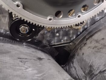
I started off this morning by pulling the protective tape from the aft baffle skirt to get an idea of the gap and general look of the bottom cowl aft baffle ribs… not bad.  I’ll note that due to the tightness of my cowling, and thus the bare minimum gap between baffle and cowl, I have these carbon fiber ribs offset just a hair aft of the baffle skirt. In addition, I’ll remind you all that these baffle ribs also serve as my bottom cowl stiffener.

Another shot of the aft side 2-ply carbon fiber bottom cowl baffle rib layups, with peel ply and tape pulled, on the left side (pic 1) and the right side (pic 2).

I needed to do a little Dremel work and rigorous sanding on the front side of these new rib layups to get them prepped for the final front side layups, so I took the bottom cowling outside in front of the shop to knock that out.

Once back in the shop, I cut 2 plies of carbon fiber for each side, peel ply patches (due to the curved surface) and a small wedge of Lantor-Soric filler material (shown below) to help in the transition to the preexisting mini-bulkhead edges.

I then wet out and laid up the 2 plies of carbon fiber each side, and peel plied the layups, again using hi-temp HTR-212 epoxy just as I did the aft half layups.

I let the layups cure for a couple of hours before mounting the bottom cowling back onto the bird.

Just after I finished the layups I jumped on a sideline task that is definitely flying related, but not specifically build related.  Since I’ll be flying again soon, with my BFR (biennial flight review) on the near horizon, I thought I would get my ANR headphones configured.

You see, a couple of years ago as I was talking to my buddy Brian Ashton (twin-engine Long-EZ builder) in Alaska, he mentioned that he had just tried out his Sony noise-cancelling headphones with an aviation mic attachment.  I thought that was cool, but didn’t take much note of it, until a follow on conversation a few weeks later… where he explained his setup more thoroughly.

The kit is as follows: you take a pair of Bose or Sony non-aviation noise-cancelling headphones and marry them up to an ANR microphone kit that is sold by avee, a company out of Norway.  I bought the mic unit (top in pic), a standard GA jack cord, and a Bose LEMO jack cord (I have both LEMO and standard jacks in my bird).  I also separately bought a Bose LEMO to standard GA jack connector from ACS.

Oh, and they’ll personalize the case for you as well!

When I talked to Brian, he was using the Sony WH-1000XM4 headphones.  Being cheap and after watching reviews on YouTube where folks noted virtually no difference (much like my recent action camera purchase) between the models, I pulled the trigger on a set of like-new WH-1000XM3 headphones off of eBay for a fraction of the price.

Now, these headphones are known to occasionally need a battery replacement after long use (or no use) and mine was no different.   It also doesn’t help when you don’t take the time to really understand how to operate something (which I didn’t)… ahem, there may have been no real battery issue at all!  Anyway, I set them aside after thinking I needed to replace the battery and never got back to them.  Well, in trying to clear out the queue of all my electronics that are awaiting repair (I recently mentioned my MacBook Air battery replacement task) the time to bring this headphone kit online was now.

After maybe 30 minutes of research and prepping myself to change the battery (more involved then just installing AA’s), I found a nifty and pertinent video showing how to reset the headphones with simple timed button pushes.  Sure enough it worked, and after a half hour charge I spent the next few hours wearing the headphones, listening to music, etc. synced to my cell phone via Bluetooth.

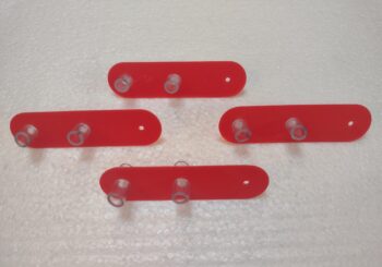
With my headphone ops function test a success, I proceeded to perform the simple task of attaching a strip of magnets to the bottom of the left ear cup, just adjacent the 3.5mm jack port.  I first cleaned the adhesive magnet strip mounting area with an included alcohol wipe . . .

Then peeled off the protective backing off the adhesive magnet strip, which comes pre-mounted on the microphone assembly (pic 1), and then plugged the microphone assembly’s 3.5mm jack into the left ear cup, keeping the entire unit pressed firmly in place for 30 seconds (pic 2).

And Voila!  I now have a set of wireless Bluetooth noise-cancelling headphones AND a pair of ANR headphones for the plane.  Pretty cool!

With the magnets, clearly you can see that the microphone assembly can be removed, but only if you really want it to.  Otherwise it stays firmly attached to the headset.

Here’s a closer shot of the magnet strip on the left ear cup of the headphones.

And another shot here of the Sony headphones, the avee microphone assembly, avee Bose LEMO cord, and the separately purchased Bose LEMO-to-GA jack.  Obviously the cord plugs into the back of the microphone assembly.  There is also a volume knob on the microphone assembly as well.

I’ll note that when I was doing my original research, after Brian told me of this cool kit, that I saw a number of positive reviews from airline pilots using this setup.  Moreover, the fact that it cost about a 1/3 of what a pair of Bose ANR headsets cost, I was definitely curious.

I closed out the evening doing a number of hours of CAD modeling work on a few different Long-EZ components.  I’ll cover those over the next few days.  For now, I’m calling it another late night.

Moving onward!

Chapter 23 – Bottom cowl baffle rib

I started out this morning attending my local EAA chapter’s monthly meeting, which turned out to be amazingly productive.

After having a nice post-breakfast chat with a local Grumman Tiger owner and my fellow canardian buddy, Guy, a group of us went over to the airport to help a fellow EAA’er, Joe, with his airworthiness inspection on his just-finished (and very nice!) RV-10.

At one point the DAR was discussing Joe’s flight test area, and after a couple of questions (and this pic) the DAR started discussing what my upcoming 40-hour fly off test area would be, since the Long-EZ is a bit faster than the RV-10.  After discussing the Airworthiness Cert inspection and paperwork process, I got the DAR’s business card… it’s great to have met face to face, discuss my bird and my build, and how to get ‘er in the air!

Moreover, a new EAA member is a new (to me anyway) CFI at the airport and we discussed doing my BFR soon… like I said, a very productive day!

By the time I got into the shop it was very late afternoon.  I spent a decent bit of time getting the contour of the lower cowling baffle rib’s “outriggers” (or ‘wings’) transferred over into cardboard jigs.  Which I then used as templates to cut out 2 plies of carbon fiber per side, and both inside and outside segments of peel ply.

With the tape on the cardboard jigs serving as mold release, I then taped them into place on the lower cowling.  After which, I mixed up some HTR-212 high temp epoxy and wet out the aft face of the jigs and the cowl surface.

I then wet out and laid up my inside pieces of peel ply, followed by a micro fillet in the corner, pretty much the entire length of the outrigger jigs.

And laid up 2 plies of carbon fiber per side.

And peel plied the carbon fiber layups.

The tricky part of this layup was letting it cure for a few hours (it was getting quite late) to allow the epoxy to get into its “green” state (just starting to really set up, but not totally cured) to allow me to pull off the cardboard jigs, trim the layups down a good bit (it was too hard to do that with the cardboard jigs in place, which was my initial plan).

I then set the jigs back in place and mounted the bottom cowling into place on the bird to allow the aft baffle ribs —which also serve as bottom cowl STIFFENERS— to cure with the bottom cowl in its mounted position.

After all that, I called it a night!

Chapter 23 – Oil hose securing tab

In prep for getting back into the cockpit in the not too distant future, plus my upcoming trip to Rough River in the back of Marco’s Long-EZ (JT), I dusted off the iPad and ensured my FlyQ EFB (“Poor Man’s Foreflight”) was up to date.  In doing so, I noticed that my iPad seemed to be going dead quicker than usual, so I found a video online that showed all the myriad of things to turn off to help conserve power.

In my fervor of getting my technology squared away, I’ve also had a few occasions over the past months to access my MacBook Air laptop to get a doc, pic, whatever off of it… just one problem: it’s been dead in the water for almost a year(?) now.  No big deal before, but it does have a good bit of info on it regarding my Long-EZ build that I don’t have on other computers.  Sooooo…. I took about 45 minutes to take it apart, remove the old “exploded” battery and find a decently cheap-but good one online.  Which I pulled the trigger on.

Out in the shop, after refreshing the desiccant in the spark plug desiccant holders, I swapped out the wing root aft heat shield screws for the final 316 stainless steel hex drive button head screws.  That actually took a good little bit to get done.

The next “quick kill” item on my list was to get the oil cooler return hose secured, since it is in the form of an arch and I don’t want it flopping around unsecured in the engine compartment.

After finding the correct size Adel clamps for the engine mount tube side and the oil cooler return hose, I then got busy modeling up a required cross-connect tab in Fusion 360 CAD.

I then post processed the newly modeled part and machined it out.  All detailed in this highly informative comparatively short video!

And here we are: oil cooler return hose securing task complete… Voila!

And just in time to shut down the shop at a decent point to take my girl out for a Friday date night.

Pressing forward… some days more than others!

Chapter 22/23/24 – Right heat shield in

Today I finished installing the aft wing root heat shields by getting right side K1000-6 platenuts riveted into place on the mounting tabs.  Again, I’ll final trim the glassed-in mounting tabs once I pull the engine off to gain better access to the tabs, and to ensure I don’t do any damage to anything on the engine.

Here we have the right wing root aft heat shield officially installed!

And here is a video I cobbled together showing a good bit of the effort that went into constructing and mounting these wing root aft heat shields.

I had to grab something off my shop work desk and was a little taken aback seeing this massive spider on the edge of the desk.  I guess he’s the new shop boss?!  It didn’t help that a few hours earlier as I was entering the shop a snake plopped down in the doorway as I swung the door open.  Critters abound everywhere here!

With the wing root aft heat shields officially installed I turned towards a task I started a few days ago: the final electrical cable runs in the engine compartment.  It took a bit over multiple days to dial in my exact plan, but I finally figured ‘er out.

Here I’m drilling out the center rivet on the engine’s aft baffle skirt to replace it with a button head screw (pic 1).  I then drilled out the rivet hole to 3/16″ (pic 2).

On the front, business side in this case, of the aft baffle skirt I installed the field wire (F-lead) and the thick #8 cable B-lead to the alternator.  I then secured those cables, as they began their trek forward, onto the front side of the aft baffle skirt via an Adel clamp.

Here we have the Adel-clamp-securing button head screw —which replaced the center rivet— now in the center position on the aft baffle skirt.

After a good bit more assessing/pondering/scheming/planning I also drilled a hole into the right engine side 7075 aluminum throttle cable bracket to add 2 Adel clamps to secure the alternator’s B-lead cable and F-lead wire in one Adel clamp, and the starter’s big yellow cable in the other.  I’m using 2 separate Adel clamps to allow me to remove the big yellow starter cable during engine removal while allowing the alternator cables to remain securely attached to the engine.

Moreover, if you look closely in the lower right corner you’ll see that I cut the F-lead wire, terminated a knife splice connector on the end, and then added more length of 18 AWG wire with the associated knife splice connector traversing the firewall into the hell hole.  This added 18 AWG length will get permanently spliced to the wire heading to the B&C voltage regulator in the nose once the firewall covering (Titanium sheet + Fiberfrax) is in place.  Having the knife splice connectors will allow me to disconnect the alternator’s F-lead during engine removal, and easily connect back together whilst remounting the engine.

Also in the lower right corner of the pic is a red Blue Sea threaded terminal, which is what the Alternator’s B-lead connects to for passing through the firewall, and will disconnect from during engine removal.

Pressing forward!

Chapter 23/24 – Left heat shield IN

It’s been a very busy and very productive last couple of days and I’m finally getting around to getting all of it into a blog post.

I started off by test-engine turning a scrap piece of the 0.02″ thick 6061-0 aluminum sheet to ensure I wouldn’t destroy it by engine turning that thin of sheet, but it held up just fine.

So I engine turned the left wing root aft heat shield first.

I made a video of this whole wing root aft heat shield adventure (coming soon) and it shows a bit more details in there. That being said, I’ll note that leaving the freshly plasma cut wing root aft heat shields overnight, without cleaning off ALL of the water residue off left some permanent water marks, which was the final tip of the scales in my deciding to engine turn these parts.

Another shot of the left wing root heat shield engine turned.

I then engine turned the right wing root aft heat shield as well.  Obviously they both came out pretty spiffy (in my book at least).  Not shown here, but in the video, I then bent the forward 1.5″ tabs 90° on the metal brake.

Speaking of video, as part of my late night research I’ve been doing over the last couple of weeks specifically, I’ve included Action Cameras [often referred to generally just as “GoPro”s].  Being cheap and wanting the best bang for the buck, I ended up pulling the trigger on a dji Osmo Action 3 camera (the 4’s are out, but there’s not a whole lot of difference between them other than the 3 is about $100 less).

I used an older, but still small, Samsung video camera for this last video to see how well it works —that my very supporting/assisting Long-EZ build (ahem, for a time… as par usual!) girlfriend Gina bought me for a present.  Moreover, I wanted my action camera in hand since I plan on testing them out to possibly weld some RAM ball mounting points onto my roll bar before I do the final sanding, priming and painting of that.

I’ve also been pondering, assessing, researching and tweaking my under-strake latch lever for popping the topside strake storage hatch door.  I drew out a dimension  I thought was good for a lever handle, then drew out a design on a scrap spam mail envelope before modeling it up in Fusion 360.  I’m trying to design these with both ease of use/maintenance/install, ease of machining (out of 6061) and as lightweight as possible.  I then 3D printed it.

I transferred the dimension of the hatch lever into the design of each left and right bottom strake hatch lever assembly.  After some assessment, I realized I got the angle wrong on the right side (it’s not a near-perfect circle like the left side) and had to rework the rectangular lever opening.

I then tested out the general fit of the lever in the left side strake storage hatch lever bottom side strake insert… looking good.

And the same on the right side.  Note that I added a little depression on one edge to allow getting a finger grip onto the lever to pull it down.  It will be spring loaded as that is what will keep the 2 strikers securely into the tabs mounted on the inside of the actual hatch door.

I then rechecked the right side with the strake storage hatch door latch lever “installed.”

And then approximated the point where it would pop the spring-loaded top hatch door open.

I’ll note that besides the 45 minutes of putting my design on paper first, and then into Fusion 360 CAD, the above pics usually took about as much time as pulling the part off the 3D printer in the house, grabbing a pic of it, then taking it out to the shop and putting the parts into the strake, and grabbing another pic.  Most of the work was done on the 3D printer while I was in the shop working on the wing root aft heat shields… speaking of which!

I marked the vertical centerlines of the 5-ply wing root heat shield mounting tabs before securing the aft heat shields in place.  I then drilled 3/32″ holes into the heat shields and the mounting tabs, before securing them with Clecos.

Here we have all the mounting screw points clecoed on the left wing root aft heat shield (pic 1) and on the right (pic 2).

To keep the heat shields’ positioning as spot on as possible, I then drilled each mounting screw out to 1/8″ and secured the shields with the larger clecos.  Finally, I drilled out the holes with a 0.138″ diameter drill bit to allow installing #6 screws.

On the left side I installed all the K1000-6 platenuts with stainless steel cherry pop rivets, since with the engine installed I couldn’t get my solid rivet squeezer into place to do its job.  This is also why I’m leaving the final trim and finish of the 5-ply mounting tabs until after the engine is removed.  I had to trim the front edge of the front tabs (both left and right sides) to get the heat shields’ position spot on, when my Fein saw slipped a bit and nicked my oil cooler… nothing but a small cosmetic ding, but annoying nonetheless.

Here we have the left wing root aft heat shield engine turned, forward and aft tabs bent, and mounted into place.  Hoo-yah!  I’m calling this a significant success! (big smile)

I got the #6 mounting screw holes drilled out through the right wing root aft heat shield, but it was well past midnight and I was done for the evening… so I called it a night.

I plan on getting the K1000-6 platenuts installed on the right side tomorrow and press forward with other engine-related component installs as well.

Chapter 23/24 – Wing root heat shields

I started off by tweaking the right strake storage hatch initial bottom side lever assembly’s fit into the aft corner strake hole… and after a good half dozen iterations this one finally fit (pic 1).  Thus my CAD model now matches reality on the bottom strake hole.  The left side, not having as pronounced of a flat segment of the hole (to allow the wing bolt securing brackets to be installed) took less iterations to dial in (pic 2).

I then added the aft tab to both of my wing root aft heat shields and cut out new, complete cardboard templates.  I then test fit those and dialed them in on both the left and right side wing roots.

To scan the wing root heat shield templates above into CAD I had to cut them in 2 pieces to get the overall length of each scanned segment down to less than 11″, since my scanner only scans normal sized letter paper (8-1/2″ x 11″).  I then modeled up the templates and combined the 2 segments back together in Fusion 360 CAD.

At this point I needed to ensure my CAD models matched the original templates before plasma cutting the wing root aft heat shields.  This is where my 3D printed pen holder for the plasma cutting table comes into play, to essentially use the plasma cutting table as a big plotter (as Marco and I did on my instrument panel years ago).  I’ll again reiterate that this is good prep work in flushing out any tweaks that need to be made before tackling the much bigger firewall Titanium sheet-cutting job that is coming up soon.

The magnets on the original plasma cutting torch base aren’t strong enough to grip the new pen mount I created, so I needed to add some clamps for assistance.  I then printed out the left and right wing root aft heat shields with a Sharpie in the pen holder… I have to say that this setup worked quite the treat!

And then used scissors to cut out the CAD modeled/printed wing root aft heat shield templates from the card stock…

to then fit check them on the plane.  The left one (pic 1) fit fine but the right side was a hair proud along the top edge (pic 2).  After some assessment, I simply took 0.018″ off around the perimeter of the entire CAD model and called it good.  I’m sure I’ll need to do some judicious filing on the perimeter of these heat shields once they are initially installed anyway.

So after spending a good 45 minutes cleaning the squirrel poop and pink insulation out of my plasma cutting table water tray, and adding more water to it, I got on with the business of plasma cutting the wing root aft heat shields. I had to do 2 cuts on the left one to get it cut out completely, and about 6 —with cutting parameter tweaks— on the right heat shield to complete that plasma cutting job.

Here we have the left wing root aft heat shield on the top, which covers about the aft 2/3rds of the wing root.  While the right side, on the bottom, is a bit longer covering around 3/4 of the wing root.

I’m still undecided on whether or not I’m going to engine turn these heat shields, especially since they’re so thin at only 0.02″ thick.  I plan on doing some testing on some scrap pieces tomorrow and will decide then.  For now I’m calling it a night.

Chapter 22/23 – Big cables roosting

After some domestic duties and running around getting errands done, today was more of a planning, assessing and design work day than it was an actual knock-tasks-out day.  It was also a spend another 30 minutes looking in all the usual suspect places for my bag of wire terminals.  Frustrating, but I found ’em.

In the background I’ve also been working on both designing and identifying parts & materials that I’ll need for the latches on the strake storage hatches.  Yes, I decided to go a little fancy on those as well with a lightweight cable latch handle situated in the ~2″ hole on the outboard bottom end of the CS spar (AKA strake) that when pulled will release the spring hinged storage hatch door on the topside of strake… very close in operation to my top cowling oil dipstick door.  Moreover, I’ve been doing some initial modeling in CAD with dimensions I took off those bottom strake access holes.

Out in the shop I spent WAY too long (nearly 45 minutes) mounting an Adel clamp around the fuel hose where it exits the engine mount.  It was a bear to get that screw in there given the limited access to those clamps, but in the end I got it done.  I’ll note that I wanted this Adel clamp at this spot on the fuel hose for 2 serious reasons:
1.  The steel 90° hose end fitting is cantilevered straight out horizontally from the fuel pump fitting, so I wanted to ensure I support the hose and not have the fitting under stress and/or slowly lose its grip over time.
2.  The Cozy Girrrls, God bless ’em, welded a reinforcement plate in the corner of the engine mount they sold me.  Well, I had literally no other way to route my fuel hose off of the fuel pump other than right where it is.  This meant removing a chunk of that reinforcement plate.  Which further means there is essentially a dull knife blade mere fractions of an inch away from my main fuel feed out of the fuel pump to the fuel injection servo.  In case scenario #1 above were to ever happen, I didn’t want the vibrating engine mount gnawing a hole in the fuel line if it lowered in position over time.  The Adel clamp is positioned as a literal physical barrier between the fuel hose and this engine mount plate edge.

In short, this just-installed Adel clamp was both an essential and critical requirement for safe operations of this engine, IMO.

After playing “find me if you can” with my wire terminals, I then spent nearly 3 hours looking at the last 3 major cable/wire runs coming off/out the lower right firewall corner.  Again, this is the big yellow starter cable, the white 8-ga alternator B-lead, and the smaller white alternator field wire.  In addition, I verified and updated my wiring diagrams to include wire labels.

My initial plan was to run these cables just above the cold air intake tubes, and hanging off a couple of the oil sump perimeter bolts in Adel clamps, somewhat as I did with the EGT & CHT wires.  However, again that pesky fuel hose is right in the way of the big yellow starter cable.

I played around with different variants of my initial configuration for quite a bit before trying a completely different southerly route with the cables hanging off outboard side of the throttle cable lever bracket.  The one slight concern I have is the cable being in the general vicinity of the fuel injection throttle lever rotating back and forth.  The gap is more than sufficient for clearance, especially once the cables are secured, it’s just the pucker factor of anything getting close to that throttle lever.

To ensure the “southerly route” was viable, I mounted the lower cowling and spent a good 15 minutes trying to peak into any crack or crevice I could find to verify clearance between the cables in this configuration and the bottom cowling.  At every point I could see it all looked good and I’m counting this routing as a very acceptable option.

As I was walking back to the house, having closed up the shop, it hit me that maybe I could move the firewall exit point for the big yellow starter cable up an inch or two to provide more clearance between big yellow starter cable and the main fuel hose in going a more VFR direct routing betwixt firewall and starter lug, via Adels off the oil sump.  I’ll take a look at that tomorrow.

Regardless, enough banalities for the evening.  It’s getting way too late.

Pressing onward!

Chapter 22/23 – EGT/CHT official install

Before starting in hot n’ heavy on the EGT and CHT probe wiring connections I did a quick check of my newly created gust locks.  On the outboard end of the aileron the gust lock went almost up to the very front part of the gap, so not overly effective (pic 1). On the inboard aileron gap the gust lock went in about halfway (pic 2), so it looks like it will work fine there.  Since I’ll have a trailing edge fence very close to the outboard aileron edge I might not use a gust lock there anyway.

On to EGT and CHT wiring…

One the main tasks here is to join the EGT and CHT probe wires with the EGT and CHT wires coming from the P10 CPC connector, which itself traverses the firewall into the GIB headrest compartment where the GRT EIS-4000 Engine Management System unit is located.

Each of the 2 wires coming from each EGT and CHT probe is already terminated with a female Fast-On connector, whereas the pairs of EGT and CHT wires coming out of the EIS-4000 —via the P10 connector— are long and need to be trimmed to length before a male Fast-On connecter is crimped to the end of each wire, to then be joined to the associated probe wire.  The EGT probes have red and yellow wires, while the CHT probes have red and white wires, all respectively.

All this is what is going on here in pic below.  I’m about half-way through cutting the long EGT and CHT wire pairs to length to marry them up with the associated probe wires.  Clearly since these wire pairs, with rather bulky connectors once connected together (plus secured and protected with a heat shrink sleeve), need to coexist in the resulting wire bundle of EGT and CHT wires, I’m trying to space the connectors out along the length of the bundle so I don’t get a massive lump of them all together in one spot… the proverbial egg in the snake.

I got about 3 wires terminated together (which I didn’t learn the trick on squeezing the Fast-On connectors together until over 2/3rds of the way done!) with heat shrink before I realized my brain fart of not checking continuity between newly crimped male Fast-On connector and associated D-Sub pin in the P10 connector.  Ahh, complacency!

I of course know the 3 wires I connected and documented them, so if any shenanigans start up they’ll be first up on the culprit list (read: I didn’t crack open those connectors).  But from the 4th wire on I ensured I checked continuity, and all of them were good.

An entire work day and work session later, my EGT and CHT probe wire terminations, connections and wire management was finally complete.  Getting up into the bowels of the engine to clamp together pairs of Adel clamps while the wire bundle is contained is a feat unto itself, as those of you that have installed Adel clamps can surely attest to.

Case in point, on the cylinder #3 EGT probe cable I needed to secure the outboard portion of the wire to keep it from rubbing on either the cold air intake tube or the oil return line.  I tried a couple different things, one using a heat shrink wrapped zip tie, but I didn’t like the results.  I punted and installed another pair of Adel clamps outboard of the first set on the oil return line to secure this cable (visible just in front of the cold air intake tube).

If you play “Where’s Waldo” you can see all 4 left side EGT/CHT probes and their wire runs to the right side of the engine.

Here we have a shot looking down into the forward right side engine compartment. You can just see the P10 CPC connector in the top right corner (pic 1) and the gray-wrapped bundle of EGT/CHT wires secured to the right side motor mount with an Adel clamp towards the top and a heat shrink wrapped zip tie mid-picture (pic 2).

I left the bundled and secured EGT/CHT wires in their natural state (chaotic…ha!) in the area under the engine since it’s not readily visible from the top (yeah, screw performance, it’s all about looks!).

Here’s a couple of shots of the aft right corner of the engine looking up at the EGT and CHT wire runs all bundled and secured.  A good bit of the craziness is again due to my spacing out the Fast-On connection points in my attempt to not only space them out to reduce wire bundle diameter, but also to avoid having the junctions meet up where the Adel clamps are installed.  This involved a good number of loops and switchbacks to get the probe wires at the correct matchup lengths.

Yeah, who knew terminating, connecting and running EGT and CHT wires was a whole sub-project in its own right?! (Any Long-EZ builder, that’s who!)

After winning my hard fought battle with the EGT and CHT wire runs, I then took a good 45 minutes to assess the final alternator and starter cable runs.  I stress FINAL since original plans of how these components will get installed always tend to get blown out of the water after other things are stuffed into place.

Case in point is my 8-ga B-lead alternator wire.  When I first planned it’s physical course from alternator to firewall, there was not a rearward-facing fuel injection servo nor a 180° carbon fiber air induction tube blocking that route.  Now clearly there is… as we used to say in the Air Force, and as I taught Jess: Flexibility is the key to Airpower! (Hoo-ah!).

Or the ‘ol tried and true statement from my EOD days: Improvise, adapt, and overcome.

And with that, I developed my plan and my task list for connecting up the last 3 wires in the engine compartment: 1) Big yellow starter cable (won’t be finalized until after firewall covering in place); 2) Alternator 8-ga B-lead:  I’ll run, attach, and terminate soon, pre-firewall; 3) Alternator 20-ga field wire: this will run through the same firewall opening as the Big yellow starter cable, and since I need to extend this wire’s length anyway (splice in more wire) I may add a connector near the firewall… assessing.

And with that, I called it a night.

Chapter 23 – Crankcase vent tube in!

I started off today by pulling the peel ply, razor trimming the overhanging glass and hitting the edges with a sanding block on the aft wing root closeout that essentially seals up the wing root area as a fire block, on each side respectively of course.  Here we have the left side (pic 1) and the right side (pic 2).  Next up will be configuring and cutting out the aft wing root heat shields in prep for mounting.

I ran out for some errands and to grab lunch with Jess.  Shortly after I returned home mid-afternoon UPS delivered the 5/8″ tube bender I ordered off of Amazon.  Well, 15 minutes later I pressed it into service to shape the 5052 aluminum tube that I ordered from ACS.

I took my time to ensure I didn’t create too much of an angle on any one bend, but even with just the normal, slow, don’t-screw-this-up! workflow it took hours for me to get this one darn tube bent to flow with the exhaust pipes AND be angled up and outboard at a good angle on the front end to intersect the black crankcase vent hose.

After countless iterations of mounting the tube, removing it, bending an angle just a hair and then remounting it, I finally got to a point where I was ready to cut the black crankcase vent tube hose to allow me to join it to the aluminum vent tube.  However, when I tried to use the big wire cutters, that mo-jamma hose just laughed at those cutters.

I tried a couple of other cutting implements, but in the end my razor knife did the job… albeit not elegantly (But I didn’t stab anything in the engine compartment or ME!).

And here we are: the 5052 aluminum crankcase vent tube installed!

And here’s a shot of the ‘middle area” with the 2 forward hose clamps securing it to the exhaust pipes.  I’ll further note that I have a temporary hose clamp on the aluminum tube to black rubber hose connection until I do final install on the crankcase vent tube (after the exhaust pipes are officially installed… soon).  When I do the final black hose to aluminum tube connection I’ll secure it with wire using my Clamp-tite tool (much lighter!).

And here we have a shot of the very aft end of the crankcase vent tube (pic 1) and the forward end with black rubber hose going up to the crankcase vent exhaust port (pic 2).

I then turned off the lights in the last 2 shop bays and placed lights on the top right side of the engine to spot any offending gaps in the baffle sealing hi-temp RTV.  I worked the right side for nearly 45 minutes before heading over to Jess’s for a late dinner.  I still have a few more difficult-to-reach areas left to do, which I’ll hit in the next day or so.

I’ll also note that as I was doing research over the last week I found an article in the COBA magazine from Mike Beasley relaying a conversation he had with Terry Schubert on making control surface gust locks.  In the article Mike said he used 0.025″ thick 2024 and then painted them red (actually he told us to paint them red, he hadn’t done so as per pics shown… poor execution in my book! Hahaha!).

With the dimensions nicely shown in the article, I spent less than 10 minutes modeling it up in Fusion 360 CAD to then 3D print one out in red ABS.  I used a thickness of 0.032″ since this is plastic, but it still came out fine.  Probably a bit more flexible then the aluminum, but strong in sheer nonetheless.  Moreover, it took me about 2 minutes to kick off 3 prints total on these, which I did over the last couple of days.  Voila!

Tomorrow I plan on continuing my engine installation push!


Chapter 23 – More heat shield prep

I started off today by pulling my unconventional wire and string off the inboard wing CAMLOC flanges that secured the respective carbon fiber closeout tabs in place.  BTW, these CF tabs are 0.03″ thick and weigh about a gram apiece.

I then spent a good 1.5 hours cutting 2 plies of BID for the inside layup on each side, and a ply of BID for both aft outside corners as well.  Plus of course the associate peel ply for these layups.  I then prepregged the inside layup BID plies.

Sorry for the not great pic of the inside 2-ply BID layup on the left side, after I filleted the corners with micro (vs flox for weight) [pic 1].   And the 1-ply layup on the aft side after adding a fillet in the corner (pic 2).  I then peel plied the layups and left them to cure.

And repeated the process on the right side.  Inside layup (pic 1) and aft outside layup (pic 2).

I then pulled the peel ply off the firewall threaded ground stud insert and tested out how the ground bolt would thread in/stick out the firewall and how the ground strap flows around the main fuel feed line to the firewall ground stud.  I’m very pleased with this mod and think it will make any engine removal or ground strap work much easier.

And it was now time to tackle the EGT and CHT wires coming from the P10 firewall engine sensor data connector (pic 1).  I wrangled all the wire pairs and got them somewhat organized (pic 2).

I then routed the EGT/CHT wire pairs down the right inside of the engine mount and secured them in an Adel clamp.

Instead of routing both sides’ EGT and CHT wires around the front of the engine, I’m taking the left side wires straight across the lower aft of the engine to the right side, then running all the EGT and CHT wires out the front right of the engine to the P10 CPC plug. I’m doing this in part to keep the EGT and CHT wires away from the bottom unshielded P-Mag spark plug wires, thus anywhere they do come in the vicinity of spark wires they cross perpendicularly as close to 90° as possible… all to mitigate EMF noise.

It may be a bit difficult to see, but here is the left front EGT cable attached to the cylinder #3 oil return tube with Adel clamps.

Here we have all the left side EGT and CHT wires meeting at the aft left corner of the oil sump where they are secured by the corner sump bolt.  Since this is an AN4 bolt I had to drill out the Adel clamp mounting holes to 1/4″.  In addition, I chucked the old star washer and installed a fresh one and torqued the nut back to its original 96 in-lbs.

Again, if you look closely I did the same thing on the oil sump bolt just to the right of the crankcase centerline where I added an Adel clamp to secure the left side EGT and CHT wires.

It was getting fairly late so I called it a night.  Tomorrow I plan on wrangling the right side EGT and CHT wires AFTER I get the new crankcase vent tube bent and installed (the tube bender is supposed to be delivered tomorrow).  Of course there’s a myriad more tasks to do on this engine install, but I’m nugging my way through them!