Chapter 23 – Top cowl stiffener

Today I got yet another task that’s long been on my list to do finally knocked out: the top cowl aft reinforcement stiffener.  Technically this is my second attempt at this, since the first reinforcement strip didn’t do I what I needed it to (which I had honestly kind of forgotten about since I set my mind on doing this new and improved version)… which with the spring back of the top cowling may be too much to ask for, but I want to try to maintain at least a 5/16″ gap between cowl and prop spinner flow guide.  It’d be a shame not to be able to use the prop spinner due to a lack of proper clearance.

Here’s another shot of my starting point, with the pour foam in place and completed last night.

I then got to work shaping the pour foam and knocking it down to about 3/8″ max height in the center, with each side beveled down to meet the cowl surface.

Here we have the final foam base of the top cowl aft cross stiffener shaped and vacuumed, ready for glass/carbon fiber, which you can see I’ve cut and is above the foam, awaiting layup.

Using Hi-temp HTR-212 resin, I then wet out the foam with micro (pic 1) before laying up the 2 plies of UNI (pic 2).

I added a strip of Lantor Soric material next (not seen), then 2 plies of carbon fiber just a bit wider than the all the rest of the plies, to secure the whole shmeal to the top cowl surface.

I then added peel ply, mainly focusing on the edge interfaces between carbon fiber plies and top cowl.

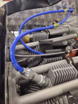
I installed the top cowl with all the CAMLOCs in place (no screw on each side) so that the top cowl would be in its final configuration during the aft cross stiffener cure.  You can see that I prepped the flow guide by hot gluing wood spacers to the surface and also clamping it to the flywheel to ensure that it’s secure during the ensuing 48 hour cure/post cure.

I then added a heat blanket on top of the cowling, just over the aft cross stiffener layup, and put a couple heat lamps underneath.  I then left it to cure… again, I’m planning on a good 48 cure to hopefully lock this top cowl position into place.

I’ll note that over the last couple of days I finally broke out the cheap toaster oven I bought late last year to allow me to heat up the wing leading edge 1/16″ plexiglass lens plates, that I bought from ACS pre-cut at 8″ x 8″ (on top of oven).

Late last year Nick Ugolini sent me his plaster of paris molds for the wing leading edge lights.  He also sent me nearly 100 pics and we had a long detailed conversation on how to create the embedded wing leading edge lights.

After looking over my personal notes, my notes on the call with Nick and some Internet research/videos, I got to work making some lenses.  The lens on the far left (below) is one that Nick sent with the forms.  The #3 smaller 5″ x 8″ lens is actually the second one I tried, the 3″ strip that I had cut off with the Fein saw being the first test piece.  It came out clear as well, and the smaller one came out pretty good too… but it wasn’t centered perfectly so it might not work for an actual final lens.

Since the corners tend to curl up a bit, I decided to leave the lenses at the 8″ x 8″ dimension that I got them from ACS.  I tried to let it heat just about 30 seconds longer to see if I could get the corners to lay down better, and lens #4 on the far right is what I got… air bubbles in the final outcome.  30 seconds less heating time and slightly curved corners is what I got on my final attempt for this go around, lens #2, second from left.

I then discovered one more final issue that really drove a decision point for me.  Although I had each lens perfectly conformed to the lens mold that Nick sent me, I noticed that the mold is significantly fatter on the bottom curve than my wing (by about 0.2″).  Nick had also sent me a piece of a wing leading edge that was cut out for making the lens light pocket, and it didn’t match my resulting lenses from the mold either.  It actually matched pretty darn close to my wing (which I would guess it should).  Hmmm?

Since the lens configuration and shape drives the exact position of the light on the leading edge, I realized that I was going to have to create the lenses in situ on each wing.  And since the top of my wings are not yet finished, I then subsequently made the call to re-sequence this task until after the wings are micro finished, epoxy wiped and sanded to final shape (but pre-paint).

Inching forward!

Chapter 22/23 – Electrons & pour foam

I started out today testing some new hydraulic crimper hex lug dies I picked up off of Ebay (technically I started out this morning with about 4 hours of long overdue mowing and yard work!).  The dies I have that came with with my hydraulic crimper have a slight gap at the edges which results in a flat “wing” on each side when I use them.  I noticed the chrome colored dies don’t seem to do that, so I took a chance on these.  And I’m glad I did.

Here I’ve terminated the alternator’s B-lead connector that attaches to the firewall-mounted BlueSea pass-thru (pic 1).  I then hit the (pre-added) red heat shrink with the heat gun to finish up the connector install (pic 2).

I then did a test install on the firewall pass-thru.  Yes, I also pre-added the white protective boot as well, although it’s looking a little rumpled here.

While I still had some daylight in the late afternoon, I took the nose hatch door and the RAM air scoop outside to knock off the old 2-part polyurethane blue boat paint in prep for some lighter (in weight) spray on paint.  Here we have the nose hatch door before (pic 1) and after (pic 2) sanding.  Yep, I have some weird low spots in there, but to be fair, I haven’t hand sanded it yet with a board.

I started losing daylight and my sandpaper was losing its grit, so I only got about half the RAM air scoop sanded.  I plan to get back to it in another few days.

I then got to work on the top cowl aft stiffener, which I marked my previous chicken scratching lines with tape (pic 1), then built the cardboard dam using the tape as a guide (pic 2).

Another shot of the finished cardboard pour foam dam.

I guess I didn’t get a shot of the pour foam in the dam, since I was in kind of hurry to get out of the shop to grab a late dinner with Jess.

But here is the pour foam after I removed the dam.

Tomorrow I’ll shape the foam and layup the reinforcement UNI, Lantor Soric and carbon fiber plies.

Chapter 23 – Air induction tube install

I had a ton of errands and chores to do today, so I was quite late getting out to the shop. That being said, I was however able to accomplish my primary goal of the day: getting the carbon fiber air induction tube mounted.

That was only possible by the delivery of this guy below (and a few more): an 18-8 stainless steel press-fit threaded standoff that I ordered from McMaster-Carr.

First off… yes, I had very much planned on making these on my own lathe, but it’s still not 100% operational in regards to CNC right now.  So I cheated and bought them as I was placing an order for other stuff.

Also, the “threaded” part of the description is not something I preferred.

So I changed that by chucking these standoffs up in the lathe and drilling out the threads.

So why exactly did I drill out the threads on these stainless steel stand-offs? (pic 1).  Because I needed to be able to seat the bolts down all the way into the standoffs, since the head-drilled bolts that I’m using all have an unthreaded shank which prevents that seating.  As you can see in pic 2, removing the threads from the standoff eliminates my bolt-seating issue.

To press-fit the standoffs into the carbon fiber air induction tube mounting flange, I drilled the 1/4″ holes out 3/8″.  I then mounted the air induction tube into place on the fuel injection servo and during the dry run fitting of each standoff, one by one, tightened each bolt to press-fit the standoff into the air induction tube flange.

Here we have all the stainless steel press-fit standoffs in place on the air induction tube mounting flange.

I then mounted the carbon fiber air induction tube by installing the mounting bolts through each press-fit standoff (and flange insert), then torqueing the bolts to 96 in-lbs before safety-wiring the pair on each side.  I will note that just as I did on the fuel injection servo mounting, I applied a very thin layer of gasket RTV to the gasket and let that tack up before installing it.

With my chores out of the way I’m hoping to get quite a bit more done tomorrow.

Pressing forward!

Chapter 23 – Even more motor bits

Today was all about knocking out more tidbit items on the engine install.  I started off by finishing up the crankcase vent tube install with some leftover tasks that I overlooked last night, with my declarative statement that I had finished said task: I first safety wired the forward 2 hose clamp screws to prevent them from loosening up.  In addition, I swapped the standard nut on the black rubber crankcase vent hose Adel clamp to an AC grade nut with washer, thus completing the securement of the Adel clamp and, in turn, the black rubber crankcase vent hose.

The next task on my list was installing a drain that pokes out of the bottom skin of the aircraft to allow nasty stuff out if and when called for… the source being either from the sniffle valve OR the mechanical fuel pump overflow.  Clearly these are sharing the same exit drain out of the aircraft, more shown on that below.

But first I had a slight configuration issue in that the bottom corner edge of the throttle cable bracket (screwdriver as pointer below) was uncomfortably close to the sniffle valve drain tube.  A decent amount of vibration could potentially see the bracket corner gnawing a hole into the tubing, so I needed to remedy that situation.

I did so by removing the Adel clamp, taking the Dremel tool and then some files to the corner to cut it down and round it over, and then reinstalled the Adel clamp on the outboard side of the throttle cable bracket/bracket.  This provided yet even a bit more clearance betwixt tube and bracket corner.

I determined how I wanted the separate drain tubes from the sniffle valve (lower left side) and mechanical fuel pump (upper right side) configured.  I then cut the drain tubes to length and attached them to a brass “Y” fitting.  I’ll note that I’ll test the separate flows of these drain tubes to ensure there’s no negative issues of running 2 tubes into one exit drain.

After determining where I wanted the external drain tube to poke through the bottom skin, I taped the external surface and then drilled a small pilot hole from the inside out.  I then drilled a 1/4″ hole up into the engine compartment (just aft of the firewall) using the small pilot hole as a guide (sorry for the pics… my camera was being a PITA).

Here’s the 1/4″ hole drilled into the external bottom skin.

I then cut a length of 1/4″ aluminum tubing, bent it slightly for clearance with the SCAT tubing, prepped it, and then added wet micro to the external surface as I slid it up into position.  I added a few extra drops of epoxy to the tiny bit of wet micro I had in the cup and threw in a good bit of flox, but still wanted it fairly wet for strength…

I then dabbed the wet flox around the base of the tube on the inside.

Before I mixed up the epoxy (Pro-Set) I cut out 3 small patches of carbon fiber to finalize the divot fills on the left side bottom cowling (2 plies top, 1 bottom).  After I laid up the CF patches I of course peel plied the layups.  Again, this is the final divot filling or patch action that I plan on doing on the bottom cowling.

Tomorrow I’ll most likely move onto the upper cowling and work to get that completely dialed in and ready for micro and paint.

Chapter 23 – Exhaust pipes installed

Today and yesterday were all about the exhaust pipes, EGT probes and crankcase vent tube final installs.  I did a final check through all my notes and also some online stuff to make sure I wasn’t missing anything.  This included a chat with GRT Avionics on the EGT probes installation.  Moreover, I needed some 5/16″ star washers that I didn’t have on hand, but was able to get from a fellow EAA homebuilder that just finished a VANs RV-10.

With star washers in hand I got to work.  In addition to mounting the exhaust pipes, starting on the left side, I also did the final install on the EGT probes, including safety wiring the probes-securing hose clamps.

Here we have the engine right side —the #2 cylinder exhaust pipe having just been installed— while I’m in the process of finalizing the EGT probe install/safety wiring on the #4 cylinder exhaust pipe before I do its final install.

Also note that the hose clamp securing the black rubber crankcase vent tube to the aluminum tube has been replaced with safety wire securing the two together… having used the ClampTite tool to get that done.

Here we have the right side exhaust pipes, EGT probes and crankcase vent tube all installed for the final time (for now at least… ha!).  I marked the exhaust pipe mounting nuts with orange torque seal as an inventory tool to identify what engine hardware has been torqued prior to engine first start.  I am fully aware that the heat of the pipes will probably burn it off in no time flat.

Since we’re discussing exhaust pipes, last night I drew up some initial exhaust pipe end caps up in CAD to kick off the design process on making breathable desiccant inserts to both keep any wannabe nesting bugs or critters out while also drying any air out making its way towards the cylinders.

Speaking of which, I made a point to examine the exhaust ports prior to installing the exhaust pipes, and all the valves, ports, etc. looked very clean and shiny.  Nothing out of order!

I plan to continue to press forward tomorrow, and since I’m running out of engine components to install I’ll be transitioning more to final cowl work before I pull the engine here in the not-too-distant future.

Chapter 23 – More engine tidbits

Before heading out the shop I broke out the manual for the Silver Hawk fuel injection servo to ensure that I got the final configuration and torque values correct for both the throttle and mixture lever nuts that went back on or were replaced during the repositioning of those levers.

But my first task out in the shop was to get some composites curing… carbon fiber specifically.  I noted when I did my thorough sanding of the bottom cowling that I had some small low spots on the outboard left side.  Again, instead of relying on thicker micro fills I’m adding a small ply of CF into each of those depressions.

In addition, when trimming the added carbon fiber plies during the bottom cowling rebuild I accidentally cut through the skin with my Fein saw.  So today I filled that cut with 3 thicker strands (left over from my West CF UNI tape) of carbon fiber to fill the gouge.  I then peel plied all the filler patches and set the bottom cowling off to the side to cure.

Back on the Silver Hawk fuel injection servo: after torqueing both mixture and throttle lever nuts to final value as per the manual, I then reinstalled a new cotter pin on the castellated nut on the throttle lever.  I then torque sealed all the mounting, mixture lever and throttle lever nuts.

I also connected and torqued the -4 hose that connects the fuel injection servo to the fuel distribution spider on the topside of the engine.  Once threaded on and torqued, and the fuel servo -4 fitting nut torqued as well, I then added torque seal to those.

In the forward left corner of the engine compartment, I got to work securing the left rudder cable CS-spar-mounted cable guide to the oil cooler bracket via an Adel clamp. I started by marking the position of the Adel clamp post.  I then drilled a 3/16″ hole at the mark.

I removed the oil cooler angled aluminum mounting bracket and mounted a K1000-3 platenut on the oil cooler flange.

I remounted the oil cooler bracket to the oil cooler permanently using AN3 bolts and AC grade nuts, before adding a spacer to set and secure the position of the left rudder cable guide via an Adel clamp.

My goal tomorrow is to do the final install of the exhaust pipes, so in leaning forward and prep for that job I removed the left side exhaust pipes.

It was getting quite late (seems to be a theme) so I didn’t tackle removing the right side exhaust pipes and crankcase vent tube, but will get that knocked out along with final pipe install tomorrow.

Chapter 23 – Final FI servo install

I got a late start on the build today, and since it was very late in the afternoon —and thus cooler— I took the opportunity to sand on the bottom cowling for about 45 minutes.  I was mostly knocking off the old blue paint, but also hit the new added carbon fiber panels fairly aggressively to knock down any egregious high spots and smooth out the surface for upcoming micro.

I then got to work on the final install of the alternator cable/wire and starter cable Adel clamps, which secure all this to the throttle cable bracket on the right side of the engine.  I needed a slightly longer AN3 bolt, a thin washer and a 10-32 star washer for the standard jam nut I’m using to secure the alternator B-lead/F-lead pair in the upper Adel clamp.  These will stay attached here on the motor and get disconnected at the firewall when/if I need to remove the engine.

On the remaining threads of the bolt protruding below the jam nut, I then secured the big yellow starter cable in an Adel clamp using a temporary jam nut.  For final engine install I’ll swap out the jam nut for an A/C grade locknut (I have to disconnect the starter cable and run it through the firewall covering when it is installed).

In addition, you can see that I covered a good bit of the starter cable with a heat shrink anti-chaffing sleeve.  I also labeled the starter cable.  After I install the firewall I’ll do the final trimming of this cable to length and crimp a terminal connector onto the end of it to mount to the starter stud.

I had also planned on getting the fuel injection servo officially installed and also the left side rudder cable guide secured to the oil cooler mounting flange with an Adel clamp, spacer and K1000-3 platenut. I completed the former, but not the latter.

In my attempt to drill safety wire holes into the 5/16″ nuts my efforts were rewarded by nothing more than a few broken bits.  And I was using higher end bits to try to punch through the tougher A/C-grade (or automotive grade 8) nuts.  Plain and simple: no joy here.  My guess is that this device is only for medium to lower grade hardware.

My backup plan from I’m guessing well over a year ago was to use these steel sleeves around the 5/16″ nuts that provide safety wire holes.  Once again I spent nearly half an hour in the “find me if you can” game since at some past shop flooding they had gotten wet and had some surface rust (just remembering this now).  They were over by my lathe where I had taken them post-flood to drench the baggy of them in oil.  That was forever ago, and I had to hunt them down tonight to use them.

I know Lycoming prefers star washers in mounting components, and I do have 1/4″ and 3/16″ star washers on hand, but no 5/16″.  I also did a quick check online and some pics I have of these Silver Hawk fuel injection servos bolted in place, and most builders used the star washers.  I do have 5/16″ split lock washers on hand so I simply used those instead, since the critical element in this endeavor is torqueing these nuts to the proper value (204 in-lbs according to Lycoming).

Before the final servo install, I removed it, cleaned each face with Acetone and applied a very thin layer of Permatex gasket RTV to the gasket.  I let the gasket RTV tack up for about 5 minutes before installing the fuel injection servo back onto the cold air induction plenum.

I only used the safety wire sleeves on the top nuts, while using just a standard washer and split lock washer on the bottom studs.  I then torqued them to value… well, the bottom ones anyway.  There was no getting a torque wrench up on the top nuts so I just, once again, followed the lead of my RV-building brethren and ensured the top nuts were on good and tight.  That being said, I still used a cross pattern while tightening the bolts.  I then safety wired across the two top nuts.

I’ll note that I safety wired the two top nuts starting on the right and going left, because I didn’t want the tail of the safety wire to come anywhere close to the pivoting throttle lever arm.

Yes, another task taking at least twice as long as I planned for, and it was quite late by the time I finished up.  Tomorrow I’ll apply orange torque seal to these nuts, and get that left side rudder cable guide secured to the oil cooler mounting flange!

Pressing forward.

Chapter 23 – Top wires & stinger

Today I finished the installation of the top spark plug wires that connect up to the Electroair electronic ignition system’s firewall-mounted coil pack.  I’ll note that I have the spark plug wires ran with somewhat low profiles since the top cowling is fairly close fitting.  I do have some room to play with to shorten the spark plug wires to bring them a bit lower for clearance, if need be.

I also gooped up the front baffle spark plug wire pass-through assemblies mating surface with hi-temp RTV and mounted those into place, spark plug wires included of course.

Here’s the “business” end of the top spark plug wires, coming through the front baffle in the installed pass-through assemblies and connected to the coil pack.  Yes, my job with these wires is not 100% complete since I need to secure them to the engine mount… which will happen later when I have the engine off the plane.

In keeping with my modus operandi of making sure every task takes as long as possible to complete(!), I spent a good 45 minutes sanding the inside lip of the prop spinner to get it to seat properly onto the the mounting flange of the spinner flow guide… about 6 rounds of sanding to dial it in.  I estimate that during this process thatI removed the majority of a ply of CF that I just added.

But as with nearly all things on this build: persistence paid off and I eventually got ‘er! Here we have the prop spinner firmly mounted to the “lampshade” flow guide for the first time since I received this spinner from Catto around 3 years ago (IIRC).  Note the #6 screws securing the prop spinner in place.

Tomorrow I’ll continue on with engine-related and other build shenanigans.

Chapter 23 – Top spark plug wires

Well, I had an entire to-do list with a bunch of stuff I wanted to get done today, including finishing up the prop spinner fit onto the spinner flow guide (“lampshade”) mounting flange.

As I made my way to the shop after getting organized, I could see the clouds rolling in and heard some distant thunder.  I also noted “my” wild feral cat that lives on my property darted into the carport post haste.  Something was afoot…

Inside the shop I pulled the peel ply and started to gather up my Fein saw to take the prop spinner outside to trim the cured overhanging carbon fiber around the edge.  That’s when all hell broke loose, the sky opened up and a virtually deluge ensued.

So, I ended up trimming the raw carbon edge over the trash can, as I literally saw water pouring into the shop from under the walls.

After a good 10 minutes over a 1/3 of my shop was flooded again… this after days of waiting for the damn thing to dry out.

In the pic of fitting the prop spinner onto the spinner flow guide, you can see that some sanding will be required for the correct fit.  That clearly means my 6 ply estimate was correct, as now sanding some of the inside edge is required for fit vs adding more material.  Thank goodness I didn’t opt for adding a 7th ply.  Also, for your viewing pleasure, I angled the camera so you could see the new round of flood waters overtaking the shop (there’s a reason why a good bit of my shop floor is rust colored!).

I was (and am) quite annoyed that a 30 minute rain shower has set me back to square zero with needing my shop to dry out once again.  I ran out to knock out some errands that have needed my attention for a bit, and upon my return I worked a good while in the house on CAD modeling… more on that to come here in the near future.

Day 2 I finally got back into the shop with my altered plan of getting the top spark plug wires assembled and installed.  I had watched the how-to video from Electroair, made myself a cheat sheet (below) to organize my thoughts, inventoried all the wires and parts, and got to work.

My first task was attaching the spark plug wires to the Electroair CDI on the firewall.  Simple task: plugging in spark plug wires… right?!  Uh, no.  This is an experimental aircraft, and will be treated as such!  Like the PMag wires, the Electroair spark plug wires require a minimum 1/4″ separation from each other.  Moreover, with my placement of the CDI right at the edge of the firewall, I can only angle the 90° spark plug wire connectors somewhat “parallel” or inward of the top cowling surface… clearly to avoid wire chaffing otherwise.

This turned into a good 20 minute machination of angling, assessing and repositioning spark plug wire runs to keep the wires segregated from each other.

Here’s my cheat sheet for cutting the spark plug wires to length and assembling the threaded aircraft spark plug connector on the plug end of the wire.  I’ll note that in the video Electroair links to, red wires are being assembled.  I have blue wires… that difference comes into play.

You see, once I got the wire cut to length and the plug end connector assembled, it was time to do a resistance check on my newly assembled wire.  Per the Electroair video we should see 475 ohms per inch of spark plug wire.  Uh, I was seeing around 30 ohms per inch.  Something ain’t right in Kansas here Dorothy!

After doing some more digging around online, I found some comments from our RV brethren discussing Electroair blue vs red spark plug wires.  Ahh, a poster confirmed that the blue wire has a way lower resistance than the red wire, about what I was seeing. A quick call to Electroair confirmed the blue vs red wire resistance values, and I was on my way after this.

Here we have the #1 cylinder top (Electroair) spark plug wire installed on the spark plug.

Yes, my build schedule was shot to hell with this recent round of rain (not to mention the tropical storm) and I had planned on getting a long day of building in yesterday, and made plans to have dinner with Jess this evening.  So after spark plug wire #1 was complete, and my wire-terminating process dialed in somewhat, I called it an early night.

Chapter 22/23 – Cowl baffle rib & more!

Ahh, tis the season!  The stormy season…

While last year a tropical storm moved up the east coast as Marco and I were ready to return from Rough River (thus an extra night at Mike Beasley’s to let the storm pass through), this year a storm hit pre-RR.  Again, nothing major except a lot of wind and rain.  More rain this time than wind.

So, it may not be surprising that I report that over half of my shop has a soggy floor, going on a couple days now. And as such, I’ve been focused on some tech refreshes (both personal and airplane) and checking out/developing my action camera mounting & use plan for the Long-EZ.

Pre-storm I did pull the peel ply from the bottom cowl aft baffle rib outrigger layups, and then marked and trimmed the newly made baffle ribs //slash// bottom cowl stiffener.

Here we have a couple of shots of the final-configured bottom cowl aft baffle ribs and stiffener with the bottom cowl installed.

Although my shop is still drying out, I was done being sidelined and pressed forward with a task that may not be critical in the initial airworthiness of this airplane, but one that’s been gnawing at me and that I wanted complete.  And that is correcting the looseness of the fit between the prop spinner and flow guide’s (“lampshade”) mounting flange that the spinner attaches to.

Many months ago I confirmed that my spinner was woefully lacking the correct number of plies when I was discussing with Dave Berenholtz cutting the spinner to mount over and around the prop blades.  He noted that he filled in the resulting notches just forward of the prop blades with carbon fiber plates he laid up using 10 plies of CF.  10 plies?!? I asked.  Why when the spinner is only 3 plies thick?  Well, apparently his Catto spinner is 10 plies at the mounting interface, while again mine is only 3 (as guesstimated with my micrometer measurements).

Since I needed to sand the inside edge to add 6 plies of carbon fiber inside the mounting interface (I’ll add more if and as required), I also wanted to get rid of some of “gob-a-goos” that were for some reason included with my Catto prop spinner.  Here is the first blob (pic 1) and then removed with the Dremel tool and sandpaper (pic 2).

And the same thing on gobagoo #2.  Thankfully that was all that remained from Catto’s build process.

With 6 plies of CF getting laid up, I stepped them with the first 2 plies going in being 1.5″ in width (or deep, maybe).  The second pair of plies going in were 1.25″ wide, while the last pair was 1″ wide.  The constant reference point was the opening edge of the spinner.

I used the high temp epoxy HTR-212 I have on hand, and peel plied the layup. I then set it aside to cure overnight.

My next task was also something I’ve been pondering over the last week.  I removed the engine starter and alternator cables and remounted them in a couple more configurations than I originally had them (with starter cable on top) before settling on this configuration below, which provides the best clearance between all cables, engine components and that ubiquitous fuel line.

To ensure the starter cable wouldn’t get gnawed through over time from the bottom cowling, I covered the cable with 2 pieces of cardboard zip-tied in place to act as a sleeve, to give me about 1/4″ thickness as reference.

I then mounted the bottom cowling and put my phone up into the right armpit air intake scoop and grabbed a few blind pics.  It may be hard to tell in this pic, but if I blow it up on my phone I can see definite good daylight between the inside bottom cowling and the padded starter cable.

I confirmed the gap by shoving my phone into the gap just near the #2 cylinder bottom spark plug to get this shot, also showing good clearance with my now settled starter and alternator cable runs/configuration.

And with all these build shenanigans under my belt, I called it a night.

Yep, pressing forward… ever so slowly!