This blog post covers the past few days of the build.
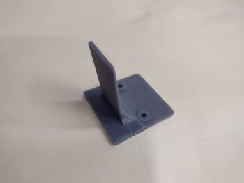
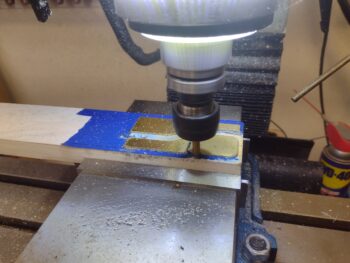
Here’s a shot of the 3D printed ABS test bracket bases to dial in the screw spacing and depth required to bury the nuts into each bracket segment.
 As I discussed in my last post, I determined that only #6 110° CS screws provide the internal clearance required for securing anything to the mounting tube innards.
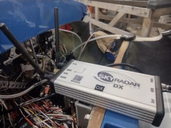
 I’ll note that I spent a considerable bit of time researching and also discussing the SkyRadar ADS-B IN receiver’s remote antenna placement and install with GRT. I also did a deep dive on acquisitioning some cable fittings, or better yet, the entire cable assemblies themselves… made to fit of course <wink>.
Fellow local canardian, Guy Williams, and I had made plans to get together last week, when/where I could update him on my build and also perhaps haul the right wing to my hangar. Well, that fell through, but a couple of days ago we agreed to make it happen today (Day 2).
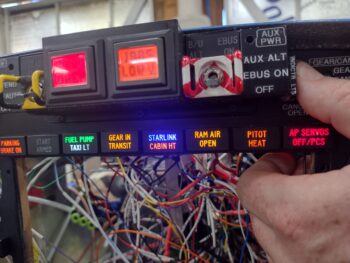
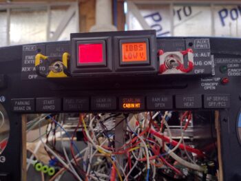
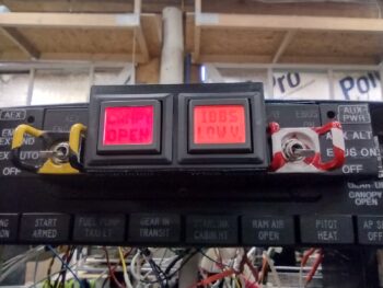
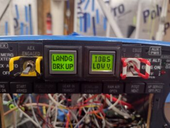
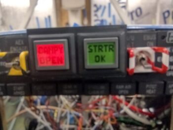
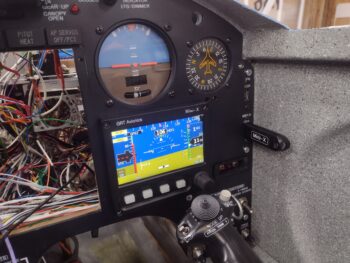
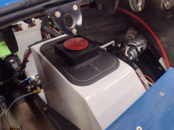
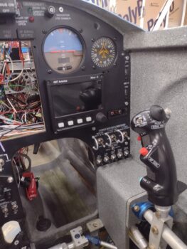
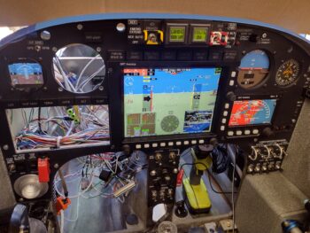
I was already prepped to do the initial install on the GRT HXr EFIS and knocked that out about 45 minutes before Guy showed up the shop. It fired up nicely, as you can see here.
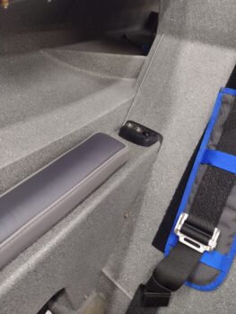
 Also on my to-do list for quite some time was getting the last of the seat belt segments installed… here we have the left bottom pilot seatbelt installed. This makes for ALL the seatbelts officially installed
 After a good hour-plus BS’ing about my panel and controls installs, Guy and I loaded up the right wing and hauled it to my hangar so it could join the left wing as they both await the delivery of the fuselage…
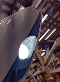
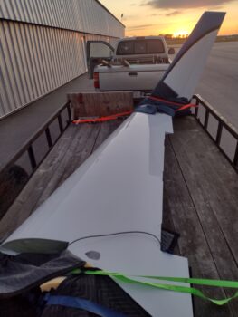
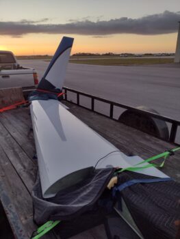
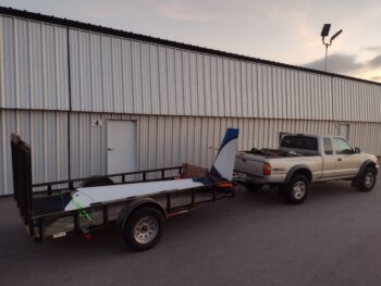 Here we have a couple of shots with the sunset in the background of the right wing, ready to be unstrapped and placed into the hangar. If you look closely, you may be able to see the collapsed wing dolly in the bed of my truck, which the wing will be placed upon before it gets installed onto the bird.
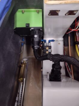
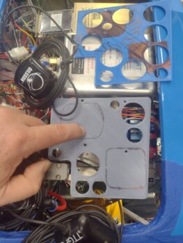
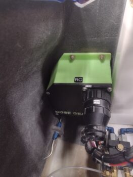
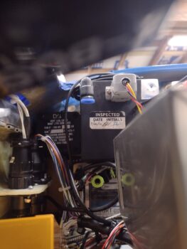
Back at the house/shop, I did some final 3D prints of the SkyRadar ADS-B IN receiver’s mounting brackets to allow me to attach the receiver to the inboard side of the Garmin GNS-480’s mounting tube.
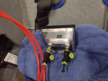
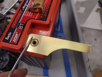
Here is the initial assembly of the first of two mounting brackets.
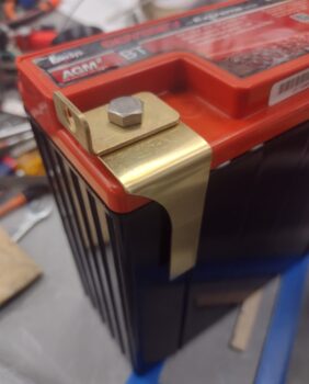
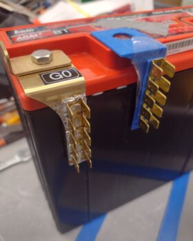
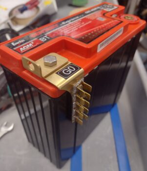
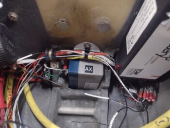
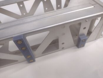
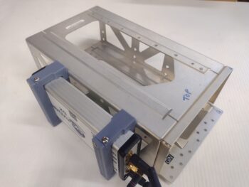
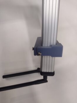 And another shot of the first bracket’s installation (pic 1), and the second bracket ready to be installed as well (pic 2). Note the threaded 6-32 brass inserts that I staked into the ABS plastic mounting bracket’s mating surfaces, with both a vertical and horizontal screw securing it on each top and bottom corner of each bracket.


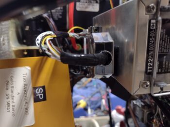
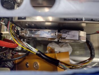
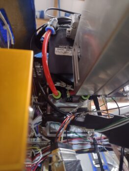
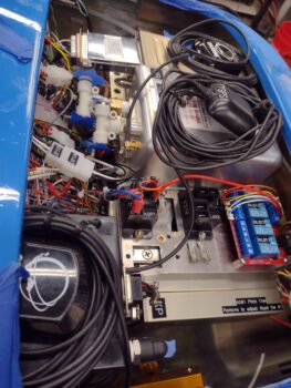
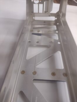
The next morning, with the brackets fitting most excellently on the SkyRadar ADS-B IN receiver, I installed the brackets first onto the GNS-480 mounting tube before then doing the final install of the receiver into place. I have to say, these brackets work a treat and I’m very pleased with them.
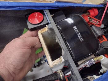
I’ll also note that the antennas mounted on the receiver’s forward end (pic 2) are the ones that will have to be removed and remotely mounted under the very aft end of the left pilot armrest. Inside the armrest of course. That gets these antennas the required >4′ away from the transponder antenna inside the forward NG30 bracket uprights in the nose.

Moreover, I’ll further note that when Guy was at the shop, I discussed with him a couple of distinct issues I was having with the GRT EFISs.
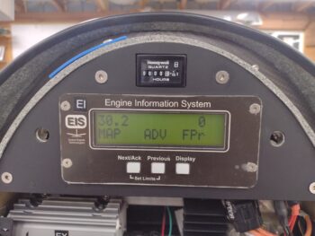
First off, I’ve been having very spotty reporting from the MIni-X’s OAT probe. And then after I installed the HXr EFIS, we could see that they were not talking to each other, although they are wired with data crosslinks.
I emailed GRT with some screenshots of my Mini-X’s OAT reporting, which ranged from nothing but dashed lines for the OAT value to a negative value which interestingly put the Density Altitude in the negative thousands. After a reply from GRT with a few things to troubleshoot —one of which was checking the settings— I decided to go ahead and update the software.
And wouldn’t you know, that seems to have done the trick [knock on wood!].
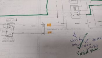
 I was then ready to remove the HXr to check out the wiring between the pair of EFISs, although after some playing around with them I did discover that manipulating the inputs on the Mini-X did change those values on the HXr, but not vise versa… so one wire appeared to be the culprit.
Well, I finally got a lucky break in that as I prepared to remove the HXr, I noticed that one of the 3 data D-Sub connectors on the back of the HXr was cocked at an angle, with the top half not fully inserted into the HXr. Ahhh, that’s something! And sure enough, with it fully seated I powered up the panel and every EIS alarm I had been getting on the HXr was now ringing off on the Mini-X as well. Thus the inputs on the HXr are now also manipulating those items on the MIni-X (altimeter, heading bug, etc.).
Serendipitously, all my <current> troubleshooting tasks on these displays have been resolved!
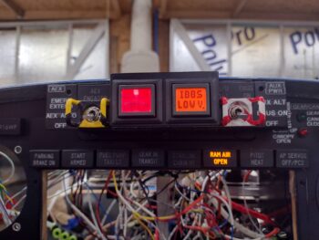
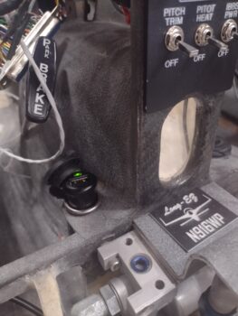
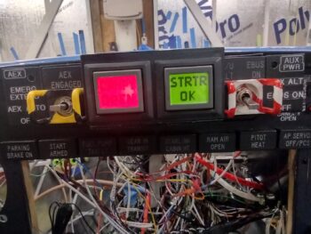
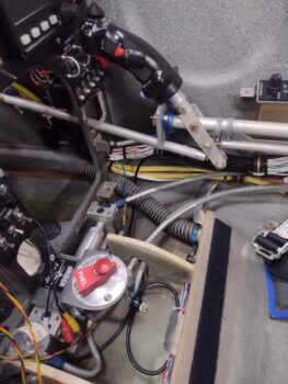
And here we have the panel with the nose poking out of the shop a hair to allow the GPS pucks to pick up their signals. I’ll also note that I updated the HXr’s software as well.
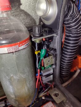
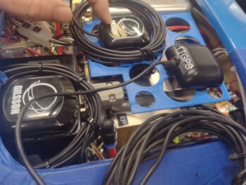
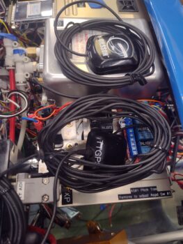
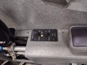
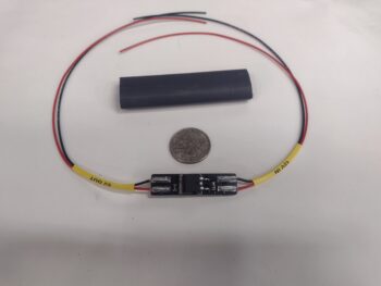
 Finally, in the mail today I got a nice surprise: the super clean (electrically speaking) 12v-5v converter that Eric Page constructed for me, replete with EZ-PZ labels to ID wire hookups. Very nice! This is of course for the one (out of 4 cameras) 5v video camera I have that needs to be hooked up to the Video Camera Multiplexer’s camera 12v power connector.
 Tomorrow will be a busy day as we prep for a quick trip up to DC for a few days. Upon my return I plan on working like a dog and wholeheartedly expect to be pretty much done with the instrument panel and electrical system install on this bird in the week following.
Pressing forward!