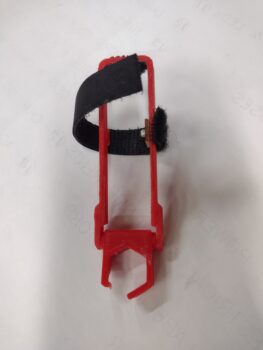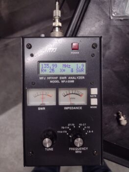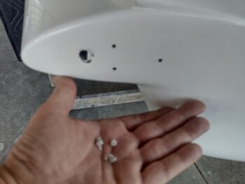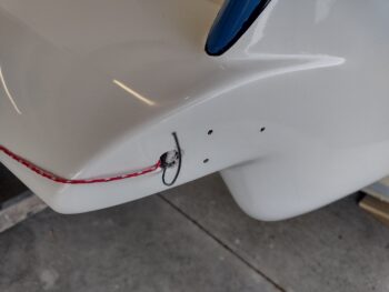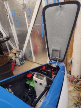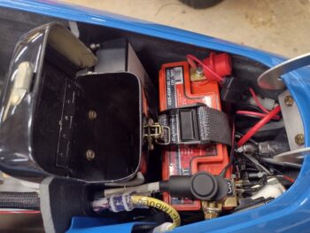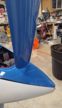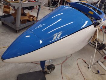
Chapter 22 – Fuel Fume Sensor Test

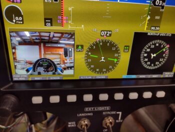
I finally got my hands on some butane to allow me to test the Fuel Fume Detector as per the manual.  A few weeks ago I held up a rag with fuel on it to the sensor, but I learned that just overwhelms it.  It’s looking for vapors, not a blast in the face.

And the butane test proved that out.  At first I didn’t think it was working, but I kept at it at and after about 90 seconds it went into alarm mode.  Nice to know the sensor works as well.

Here’s a quick video showing the control head in the alarm state from the test.

I will note that I was using the (very) old, small nose gear backup battery to power this test.  I believe with full power the top center red alarm light will be brighter.  We’ll see since it was brighter when I tested the alarm previously on startup.

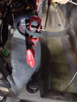
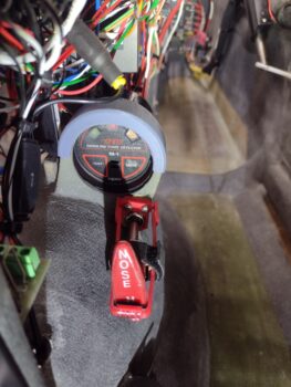
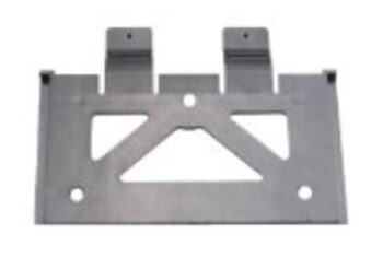
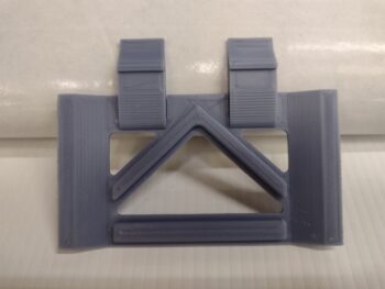
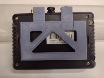
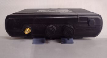
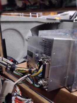
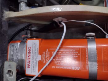
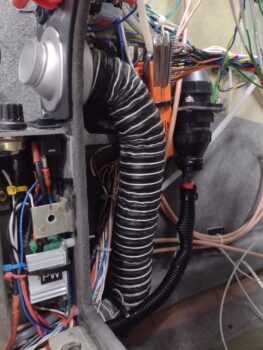
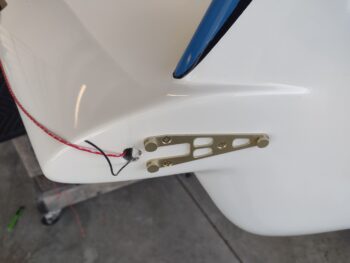
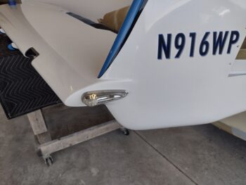
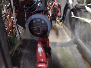
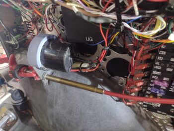
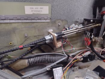
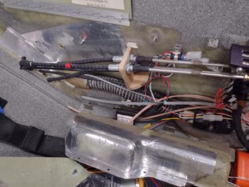
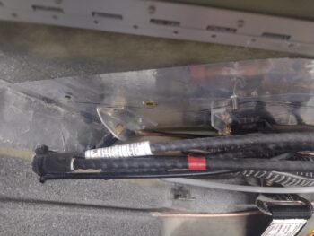
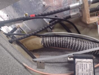
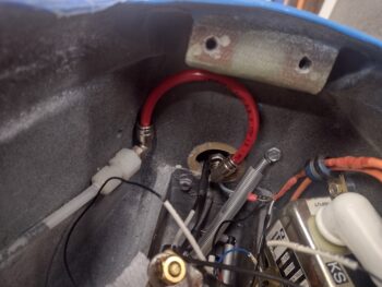
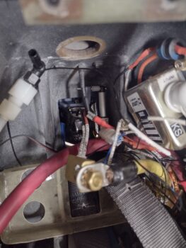
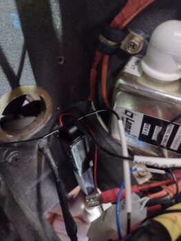
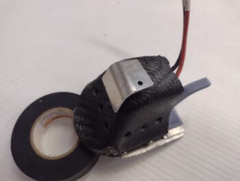
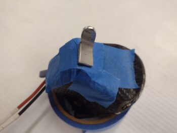
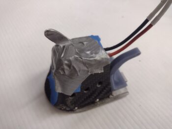
With the test good I pressed forward with mounting it into the bird.  I slathered the inside of the gray sleeve with RTV, slid it in place onto the fuel detector’s perimeter flange then slid both of those firmly into place on the mounting tab (pic 1).  I then terminated and connected the wires and wrangled those with some zip ties (pic 2).

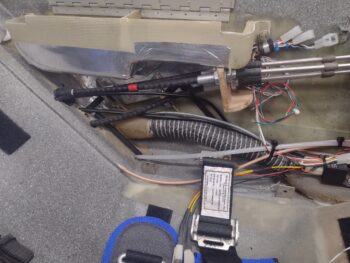
Fuel fume detector unit install complete.

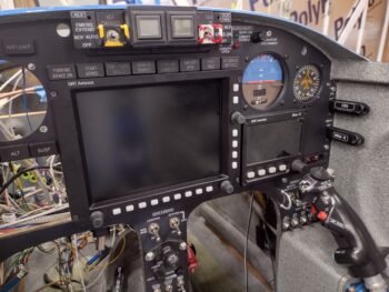
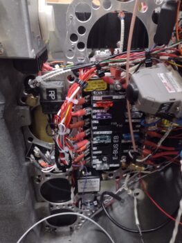
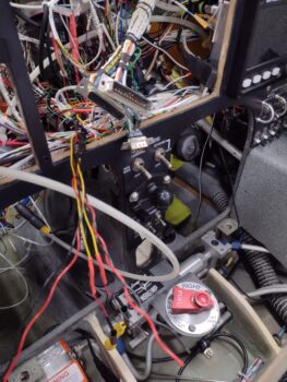
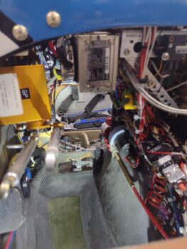
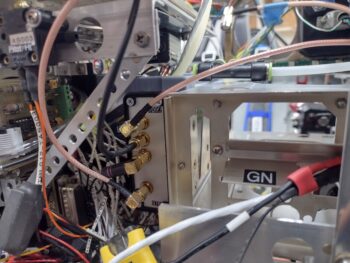
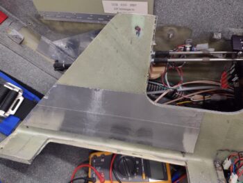
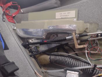
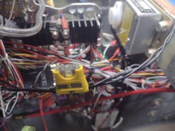
Concurrent to testing the fuel fume detector, I spent a couple of hours finalizing the wire management on the right side of the Tri-Paragon/avionics bay.

Here’s a shot of that… it’s ready for flight operations to commence!

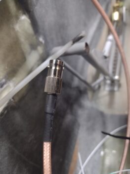
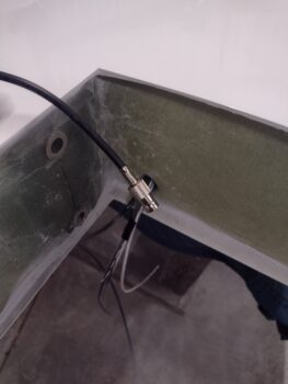
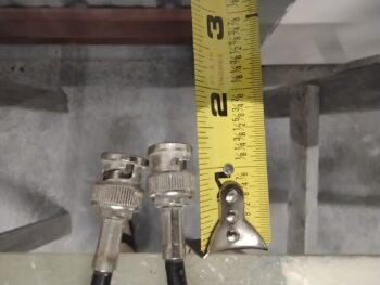
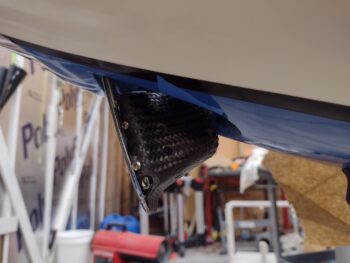
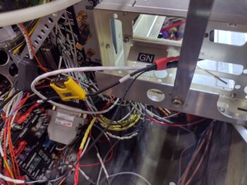
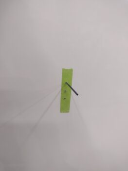
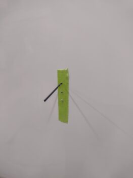
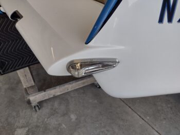
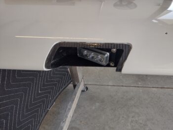
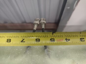
Earlier in the day I stopped by the hangar to grab some measurements of the cable connectors for the antennas embedded in the canard.  My reference point in pic 1 is the center hole of the left upper canard mounting tab.  And in pic 2 I’m simply going off the trailing edge.

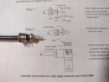
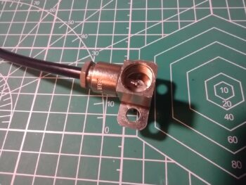
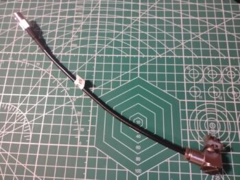
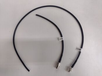
With those measurements, back in the shop in I was able to determine the length required for the NAV antenna pigtail and cut the new RG-58 cable I just received in prep of terminating it into a specific 90° connector for the GARMIN GNS-480.

As you can see, the remaining cable segment will be used as the COM1 pigtail out of the GNS-480, terminated as well into a 90° connector.

I did a good bit of work finalizing the plan for the pitot system as well and, again, deconflicting a bunch of wires to better organize them for HXr and GNS-480 install.

Pressing forward!
Chapter 22 – ADS-B IN antennas in

Another 2-day blog post here.  Day 1 was a lot of research on replacing the internal battery on the GNS-480, messing around with the nose taxi light and assessing the pitot tube cross-connection to the embedded pitot tubing in the nose.  I was supposed to get my antenna cables delivered, but realized that was not going to happen.

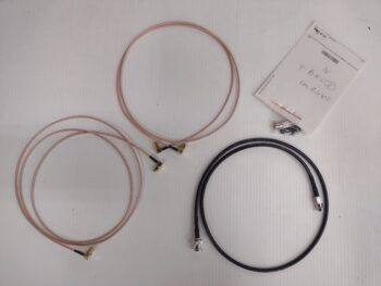
DAY 2: My ADS-B IN receiver antenna cables arrived today.  In order to have 90° female connectors on the antenna ends I had to go with the smaller diameter RG316DS cable (narrower version of RG400).  The 3 ft. black cable is RG58 with a male BNC and a female BNC connector at each end.  I’ll cut this cable into 2 pigtails that will connect to the GNS-480 for the VOR/LOC (female BNC pigtail) in the canard and the COM1 antenna (male BNC pigtail).  In the upper right corner is a female BNC connector to terminate the RG400 COM1 antenna coming in from the right wing (the CoaxRF bubbas were nice enough to throw that in for free).

I attached the longer 5 ft. ADS-B IN antenna cable to the “back” of the SkyRadar receiver for the bottom 978 MHz antenna.  I actually preferred a 4.5″ cable here, but they only make the cables in 1′ increments, thus the 978 antenna will be mounted further aft on the sidewall than the 1090 MHz antenna… also connected on the top of the receiver.

I then checked the connections to the antennas on the sidewall, initially with the storage bin removed.

I then spent the next couple of hours applying metal tape to the sidewall and the underside of the left armrest storage bin to create the antenna ground plane that is a requirement for remote mounting of the antennas as per the manual.

I also added some tape on the inside of the armrest for the inboard side of the ground plane.  I will note that I confirmed continuity between the sidewall and the underside of the storage bin.  However, I haven’t yet tested continuity between those and the armrest portion of the ground plane.  I’ll do that when I do the final install on the armrest.

I then did final check of the antenna positions, cable runs and storage bin clearance before making up the antenna mounting brackets.

Another couple hours later I finished hand-jamming some brackets up for the ADS-B IN antennas.  I didn’t want to glue, flox or RTV the antenna brackets in place since I want electrical continuity for the antennas to the ground plane.  I then planned to rivet the brackets to the sidewall but had near zero clearance between the throttle cables and configurations of the brackets themselves.  So I used multiple #4 wood screws on each bracket to secure them.

Another shot of the ADS-B IN receiver antennas mounted to the left sidewall in their respective brackets.  After I took these pics I overlapped the brackets with foil tape.

I then re-mounted the left armrest storage bin in place and confirmed continuity between the antenna brackets and the ground plane on the bottom of the storage bin.

In talking to Bob from TCW Tech regarding the IBBS install, he stated that the IBBS’s through-put power is fused… but after some thought, since my X-Bus/IBBS connected components are low-amp units, I decided to individually fuse them to ensure they’re protected (this renewed outlook was largely in part due to Marco’s issue with his Mini-X units getting damaged, even though they were both protected with 1-amp circuit breakers).

That all being said, I cut the power wire to the SkyRadar receiver and soldered in an inline fuse holder.   This officially completes the SkyRadar ADS-B IN receiver with remote antennas install.

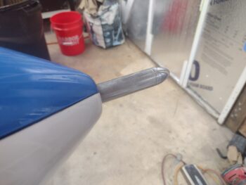
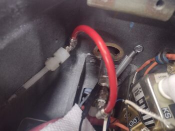
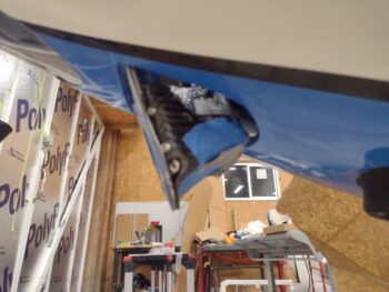
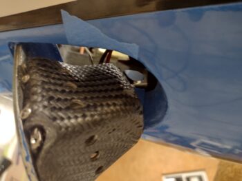
My last task of the evening was to install right angle 90° swivel connectors onto the pitot tube and the pitot line coming into the nose battery compartment (pic 1).  And here is the pitot tube, with pitot line attached, deployed for flight (pic 2).

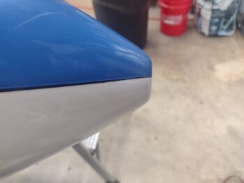
And finally, after a half dozen machinations, here is the pitot tube stowed for parking (pic 1) with the red pitot tube cross-connect not mangled or bent… thanks to the swivel connectors (pic 2).

And with that, I called it a night.

Chapter 22 – Getting there . . .

Slowly!

This blog post covers the past 2 days.

Speaking of past… years ago I discussed getting better weather than ADS-B into the cockpit.  StarLink was not around then but SiriusXM weather was, and still is, available.  Currently the variable remains on exactly how to bring SiriusXM weather into the cockpit, by either A) GRT HXr EFIS or, B) some other display.

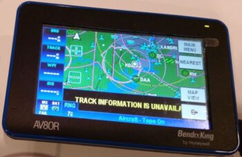
After recently updating the software on my GRT HXr, and reviewing the change notes, the assessment in regards to SiriusXM weather on the EFIS is that there has been NO significant increases in display capabilities on the GRT boxes.  With StarLink’s current plans being cost prohibitive, I’m being driven back down the cattle chute of my original best-option weather reporting in the cockpit:  SiriusXM weather displayed on my Bendix King AV8OR GPS unit… which displays nearly everything SiriusXM reports.

The only current issue with the AV8OR is that it won’t turn on.  A somewhat known common problem with these units’ on/off button after they get a little long in the tooth. Not to worry though (at least yet) since the same guy that can magical rejuvenate GNS-480 GPS navigators can work his same magic on AV8ORs as well.

That all being said, my Bendix GPS is now on its way to Chris Short in Minnesota to be repaired and brought back to operational status.

I also did a fairly in-depth review of the process, subscription, etc. to update my nav databases on the GNS-480 GPS.  I figured before I pull the trigger on that I should see if I perhaps need to also send the GNS-480 out to Chris for some TLC as well.  And, moreover, to make sure the unit actual is working!

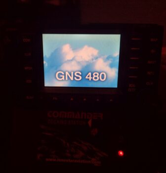
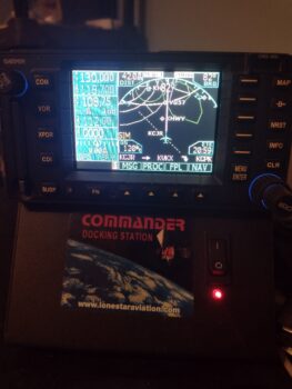
Thus, I set up the docking station, mounted the GNS-480, and fired ‘er up.

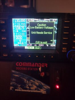
Not surprising at all is that I was immediately met with a Low Battery Voltage Caution that is common on these units as they age.  Marco had to have his battery replaced within a couple years of installing his GNS-480.  And they actually can operate fine if this battery goes dead, it just takes longer to boot up on every power-up since it no longer can remember where it is in the world.

I actually have the replacement battery on hand and will be swapping it out myself in the near future.  I figure I’ll wait until I’m ready to start flying IFR before I send the unit out to Chris to have him refresh some of the older capacitors, resistors, etc. that are known to get a little wore out over the many years these things have been in service.

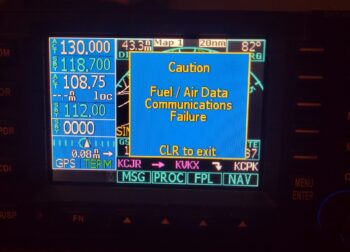
Since the GNS-480 is not in the panel and talking to the HXr EFIS, specifically the AHRS, I got this caution as well.

And after all that, I played around and refamiliarized myself with the GNS-480 for about 10 minutes before calling it operational and ready for duty (after battery swap).

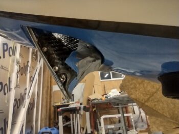
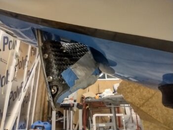
Back in the shop I reset the position of the Taxi Light spring mounting tab before testing that configuration out.  Which is still a NO-GO.  As you can see, with the angle, height of the light assembly, and slim clearance… it’s just a tight fit in the rotation of the light.

I moved the spring tab forward on the light cover and then tried it again.

Success!

Here’s a shot of the taxi light assembly with the now riveted-in-place spring tab (yes, busy in that nose). I will note that when I removed the carbon fiber light cover to rivet on the spring tab, I also safety wired the light bulb to the frame, which centered it better in the lens.

Here is the light in the down position WITHOUT the spring attached.

With the light in the closed/up position, and the spring attached, I then powered up the circuit and tested clicking the switch for the light to deploy.  Nothing happened.  Or at least it appeared nothing happened, while actually 2 things happened.  First, what little movement (or even possibly the spring?) there was, the ABS pivot arm base cracked. Second, the Actuonix L12 actuator proved too weak to deploy the swing-down light assembly with the spring attached.

I went back to review the specs of the Actuonix L12.  Looking at online resources and reviewing Marco’s mechanical to electrical conversion for his landing/taxi light deployment, I came to the conclusion that I need the more robust and powerful L16 actuator model, versus my standard-strength L12 unit.

Now, here’s the kicker… for the size I need there are no L16 units available anywhere.  All are on back order.

Moreover, I different model actuator means slightly different mounting dimensions… which actually doesn’t matter since I am going to rework the actuator geometry to a more “traditional” vertically oriented top-pushing-down setup somewhat as I have pictured here (now that I know I have the real estate to do it):

Final conclusion on the Taxi Light?  For now I’m beefing up the ABS pivot arm, using the L12 actuator simply to hold the pivot arm/taxi light in the closed position, then mounting the spring to also hold it in the closed position WITH B-seal around the light hole edges to minimize air leaks… Then the electrical connection will be disconnected and I’ll deal with the taxi light system after I get this thing in the air.

In other news.

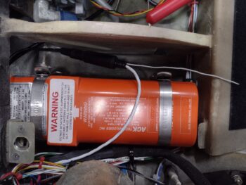
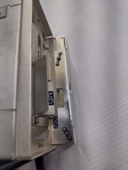
I took the 3-conductor shielded cable with terminated ELT connector out to the shop and connected it to the ELT-side connector.  Note that I’ll secure the connector in the ELT bay under the pilot thigh support so it’s not flopping around.

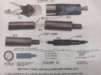
Here’s the page from the ACK E-04 install manual where I’ve annotated the wire colors.

I’m focusing on this task now because this is currently the last bit of wiring that needs to be routed across the top of the left leg hole and down the side of the left panel wiring bundle before I wrangle all the left side wiring into something that looks a whole lot more respectable… to allow for the final install of the GNS-480 GPS and the Trio autopilot into the panel.

Again, as per the install manual above, I spliced one of the 3 wires to power via an inline fuse (yellow) to the E-Bus fuse panel stud.  Wire #2 connects to cable shield and ground (still to be labeled and terminated).  I then crimped a D-Sub socket onto the end of wire #3 —the entire purpose of this cable assembly— to terminate it into the P1 connector of the GNS-480.

This gives the real juice to the 406 MHz capability of this ELT in that if it experiences enough G-forces that would indicate a crash landing, via the GPS data it can report to CAP, etc. pretty much exactly where you are… reducing search time from hours to exponentially less time.

Pressing forward.

Chapter 13/22 – Canard to hangar

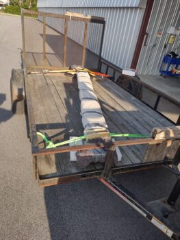
Today was a good bit of spring cleaning.  I took a couple bags of shop trash along with a few house trash bags to the dump on the way to the airport to deliver the canard to the hangar.

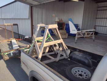
Of course I’ll need to store the canard before it gets mounted onto the airplane, so I brought along the converted/reinforced wing/painting sawhorses.

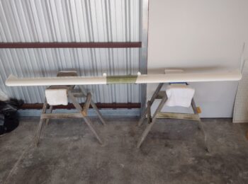
Here we have the canard in the hangar, still wrapped for transport after I picked it from Phil’s shop (where he buffed out the paint).

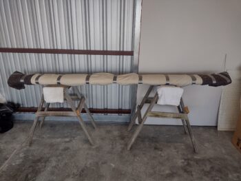
I then removed the protective transport wraps… Voila!  Canard is officially at the hangar.  I’ll note that once I ensure the elevators are balanced, I’ll bring them to the hangar and install them on the canard.

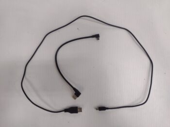
After returning home, I saw that my SkyRadar ADS-B IN receiver much shorter, right angle USB cable had been delivered.  This 9″ cable will replace the current 3 ft. cable to make for a much tidier install between the SkyRadar receiver and the HXr EFIS’s USB hub.

I’m not sure if I’ve reported this yet, but when I checked continuity on the left fuel site gage video camera’s 3-wire connector, the power wire was not showing good.  Those 3 wires are part of a 5 wire cable where the final 2 wires power the fuel site gage’s and strake baggage compartments LED lights.

First, the 3 wire video camera connector cable is spliced into the 5 wire cable near the original fuselage sidewall inside the strake baggage compartment… hard to get to.  Second, I apparently got my wire color scheme (as per diagram) mixed up and had to play around with the wires for a bit to figure them out (a month back).

I’ve been pondering on how to repair the wire when I finally got around to testing the right side fuel site gage video camera lead.  This time with actual video camera on hand (from the house) to check the wire coloring scheme.  So my initial thought on the left side was that the yellow video feed wire was dead, but I was wrong.  It was power…  And wouldn’t you know that the same thing played out on the right side: the power wire failed the continuity test.  Now, I know there is a small PCB in the camera connector leads, so I’m thinking some component is quite likely not allowing end-to-end continuity until power is applied.  I say that as it seems very unlikely (but possible) that I jacked up only the power wire splicing on BOTH left and right video cameras.

Thus, I’ll operationally test the cameras first before engaging in any corrective action.

I then got to work on the Taxi Light.  I’m mounting a small tab on it to attach a closing spring to ensure the taxi light is under pressure to close at all times.  To do this I created an initial reinforcement/tab-mounting plate (pic 1) and then the tab itself (pic 2)… both from scrap pieces of aluminum (and yes, I’ll protect the mating surfaces from the carbon fiber).

I then popped the taxi light into the nose and moved it inward to close… wow, way less room than I thought!  A definite no-go on this tab position on the aft face of the light.

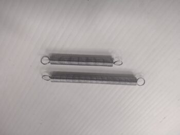
I’ll note exactly due to the positioning scenario above, I bought 2 different spring sizes to account for different positioning requirements.

I then moved the spring attachment tab to the top of the taxi light cover, still angled aft.

Hmmm, with the closing angle of the taxi light into its opening, barely any noticeable difference than above!  Still a NO-GO.

Tomorrow I plan on significantly shortening the height of the spring attachment tab and then test out its positioning on the taxi light cover again.

It was getting late and I only had about 10 minutes before I needed to close up shop to rendezvous with my wife, Jess, for a late dinner (she worked tonight).  So to get one more task off the list I quickly taped up the 3 static ports on each side of the nose.

You see, the original holes were 1/16″ diameter as per the plans BEFORE paint, but clearly not afterwards.  The goal was to get the holes back to 1/16″ diameter without chipping any paint from around the holes (read: clean!).

I started with a 0.048″ bit and drilled the holes, by hand, progressing up to 1/16″ (0.063″) through 0.052″, 0.055″, 0.059″ sized bits to again ensure no paint chips!

Requirement met and task completed: here we have the right side static holes (pic 1) and the left side (pic 2) all at 1/16″ (0.063″) diameter and vacuumed out clean.

And with that, I called it a night.  More to follow tomorrow.

Chapter 22 – GNS-480 support arm

My wife had a day off since family is in town, so I spent the afternoon with her and had some lunch down by the water.  A nice little break from the build.

I then reviewed and did some background research on antenna cabling, my electrical notes, etc., so I didn’t make it out to the shop until early evening.

I worked on the initial bracket and spring attachment tab that I plan to rivet to the taxi light to add a spring between taxi light cover and the forward nose bulkhead to ensure the taxi light always retracts into the closed position, assisted or not by the actuator.  No pics of all that as I’m just in the initial assessment phase.

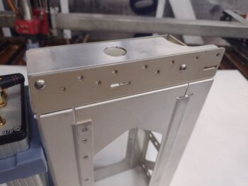
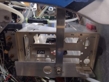
I then riveted the 2 each K1000-6 platenuts onto the GNS-480 bracket that I just machined to allow me to mount that via the pre-existing holes in the bottom flange of the mounting tube.

Here we have the 2x K1000-6s installed onto the bracket, which then allowed the bracket to be attached to the GNS-480 via two #6 screws.

And a bottom view of the 2 screws securing the bracket to the bottom flange of GNS-480 mounting tube.

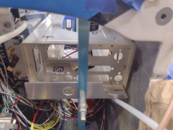
I then temporarily installed the GNS-480 mounting tube inside the avionics area, securing the tube to the instrument panel inner edges with 2 screws on each side.

Note the blue plastic covered 2024 aluminum support hanging down from the Clickbond mounted on the aft side of F28 (upper left corner).  Also note the new 45° SkyRadar receiver mounting bracket (lower right corner).

And here is the 2024 aluminum support arm drilled and clecoed to the attached lower bracket.

I then trimmed the support arm to length, drilled the hole to attach it to the support bracket, pulled the plastic and cleaned it up.  On the bracket itself, I installed a K1000-3 platenut to allow attaching the support arm to the new GNS-480 mounting tube (obviously via the bracket).

This ends the configuration prep for the GNS-480 tube.  After I get the left-side panel wires wrangled and secured I’ll do the final install of the GNS-480 mounting tube, replete with the wiring harness and antenna connectors.

Chapter 22 – GNS-480 bracket

This post covers the past couple of days.

First off, I ordered another stylus for my Centroid Acorn CNC probe.  Centroid has a program where you can send your probe back into them for calibration and even replacement if needed, but it’s a one time event in the life of the probe and you still have to replace any missing stylus.  Since my tolerances aren’t (read: can’t be) super tight on this current mill, I just ordered a new stylus.

As promised, here is a shot of Taxi Light pivot arm #7 (pic 1), with pivot arm #6 (pic 2) and pivot arm #5 (pic 3) added for comparison.   Clearly I need a runoff between #7 and #5 to see which final version will get installed currently…  again, with plans to tweak the geometry after the bird’s in the air.

In poking around in the remaining panel areas that still yet need to get populated, I stumbled upon a clearance issue between the SkyRadar ADS-B IN receiver’s aft bracket and 2 of the 3 connectors on the backside (technically front) of the HXr.  The HXr frame will clear the actual SkyRadar unit but its protruding D-Sub connectors will not clear the mounting bracket.

Also note the USB cable off the SkyRadar unit, which is 3 feet long.  The USB hub that it connects to is 6″ away.  So I ordered a new 9″ cable with a 90° mini USB connector  that will mount into the SkyRadar aft face… again to optimize clearance with the HXr.

I spent nearly an hour in CAD modeling up a new bracket that is simply a 45° version of the current retaining bracket.  Clearly the bracket is mounted away from the HXr, which SHOULD provide clearance for the HXr’s D-Sub connectors.  My last task of the evening of Day 1 was kicking off the 3D print of this guy, which took about 2.5 hours.

This morning I staked a pair of brass threaded inserts into the SkyRadar’s new angled mounting bracket before taking it out to the shop for install.

As a reminder, here is the original pair of brackets (pic 1).  And here is the GNS-480 mounting tube with the SkyRadar ADS-B IN receiver’s new 45° foward-biased bracket (pic 2).

I then got busy machining the “aft” angled bracket of the GNS-480 tube that will help wrangle and secure all the wires and cables connecting to the GNS-480.

As a reminder, this is a close copy to what Marco has on the “aft” side of his GNS-480.  Note the red support arm that is bolted to this bracket and to the aft side of the F28 bulkhead.  This is probably the most important feature of this bracket and, if you remember, I already installed a Clickbond on the aft side of F28 just for this purpose.

Here I’m machining the vertical wall of the angled 6061 aluminum to create this bracket.

And here is the finished machining of the vertical wall of the bracket.  I put the 3D printed model in the shot for comparison of 3D model vs machined part.

But wait just a darn minute you state emphatically!
“Didn’t you crash and destroy the stylus of your probe?” — Yes.
“Didn’t you have to order a new one?” — Yes.
“I guess you’re finding Z0/X0/Y0 via ol’ skool machining methods then?” — Hell no!
“Then what in tar-nation is going on?!”

Interestingly enough, Centroid has the dimensions and threads of the probe stylus listed on their website.  Again, since my tolerances aren’t critical for this part, I simply modeled up and 3D printed a stylus to get this job done, and pressed forward.  Improvise, adapt and overcome!

Here I’m using the 3D printed stylus to determine zero for all axes before machining the bottom of the GNS-480 bracket.

Although there are 2 screw mounting holes in the bottom of the bracket to mount it to the GNS-480 tube, I only used the mill to drill one of them.  After I secure the bracket to the GNS-480 tube I’ll drill the other hole to ensure they are spaced just right to line up with the pre-existing holes on the tube flange.

I then machined the bottom bracket angle leg using a 3/16″ 2-flute end mill (pic 1). Again, here is the machined angle bracket pictured with the 3D printed model (pic 2).

And one last shot of the machined GNS-480 mounting tube bracket and the 3D printed model.

Using the single bottom mounting hole I then attached the bracket to the GNS-480 tube with a #6 screw.  With the single screw in place and using a clamp to secure the bracket, I then drilled the other screw hole and installed the 2nd screw.

Tomorrow I need to attach a #6 platenut for each screw, but before I do that I’m going to assess whether I should machine some zip-tie slots along the top edge of the bracket… in the same manner I machined the zip-tie slots on the GPS puck plate.

Here is the GNS-480 tube with the bracket temporarily secured with a pair of #6 screws.

And this shot shows the where the 90° antenna cable connector is mounted to the actual GNS-480 tube back plate, and the large hole in the bracket that provides clearance for that antenna connector.  On the lower right side in this pic is another 90° antenna cable connector which is why there is a large scalloped portion removed from the bracket [there is also a third 90° antenna cable connector in the upper right of the pic, which clearly has no clearance issues with this bracket].

Tomorrow I plan on finishing the install of this bracket, including making and installing the support arm from F28 to the bracket.  Part of the GPS navigator install prep will be firing up the GNS-480 in its simulator station to ensure all is good with it before I mount it into the panel.  I will also work to finish up the Taxi Light pivot arm install in my quest to get the nose battery compartment squared away and ready for operations.

Pressing forward!
Chapter 22 – Puck Plate Installed

Yes, I plasma cut the GPS antenna puck plate yesterday and then machined the slots for the zip ties today.

I had an unfortunate (and costly) incident while machining this part: my mill drawbar is getting old and sticks a bit, often needing a sharp rap to free the tool in the spindle.  Well, in that process I lost control of the probe and it crashed into the upper left corner of the part below, shattering the stylus on the probe.  Nothing that $100 and another round of dialing in and configuring a new probe won’t take care of (sigh).

Regardless of my woes, the show must go on.  Here we have the puck plate ready to install.

Since I won’t have the required access after the puck plate is installed, I went ahead and preinserted the zip-ties in prep for securing the GPS pucks’ wiring bundles.

I then finished physically installing both the puck plate and 3 GPS pucks atop of it (HXr/ AHRS, TruTrak ADI, and MiniUni2 Mini-EFIS).  As you can see, all the copious amounts of included cabling has been wrangled, or in the case of forwardmost MiniUni2 GPS puck the cable is routed over to the left side of the avionics bay via the aft side of the F28 bulkhead.

I then continued on in my quest to find the most reasonable configuration for the Taxi Light pivot arm, with pivot arm #6 making its debut.

And here is pivot arm #6 in the up/closed position.

And also some exterior shots of it in the closed position (pic 1) and the open position (pic 2).  Again, at this point the closed position is more critical to get this bird in the air than the open position.

That being said, you can see the angle of the open light —which should be close to parallel with the ground— pointing downward a good bit… as in not stellar open fashion.

Thus after some assessment, I introduced a significant configuration change with pivot arm #7 to hopefully optimize both the open and closed taxi light positions. . .

Which works pretty darn well in the closed position.  Open position?
Doh!  Apparently I didn’t grab a pic.  I’ll include a pic in my next post and discuss.
I almost forgot to show that yet another indicator light is working as designed, with the TAXI LT on light firing up when the taxi light is deployed out of the nose.

I’ll also note that after a couple of discussions with the “WiFi Expert” cable gurus out of Valencia, California, I pulled the trigger on the 2 ADS-B IN receiver antenna cables, as well as the pigtails for the GNS-480 connections to the VOR/LOC antenna (in the canard), COM 1 radio antenna, and GPS antenna puck (top of pilot headrest).

I’ll continue to press forward in these extended wrap-up actions to get the electrical system, components and panel instruments installed and operational.

Chapter 22 – Puck Plate Plasma cut

Although there are a myriad of pics here regarding the slow design convergence towards the final Taxi Light pivot arm design, there is a video at the end of this blog post showing the plasma cutting of the GPS antenna “puck plate”… for mounting the plethora of GPS antenna pucks I have on hand.

That being said, here is the inside of the nose with the Taxi Light assembly in the up/ closed position with pivot arm #3 just before I removed it.

And this would be version #4.  Notice how each version keeps getting taller?

And here is version #4 shown deployed from the inside of the nose.  I’m not fully securing the pivot arm with a nut just yet to keep from breaking anything during my assessments.

And here is how pivot arm #4 looks from the outside.  The not-quite-so-closed position in pic 2 is not necessarily the pivot arm’s fault, as the sides of the taxi light assembly are catching on the inside sides of the nose opening.  Some clearance-creation actions may be required.

And pivot arm #4 in the closed/up position.

While taxi light pivot arm #5 was 3D printing, I filled up the plasma cutting table’s water tray and aligned/secured the 0.032″ 6061 aluminum plate to be cut.  I also hauled my laptop computer out to the shop to run this operation.

And here we have pivot arm #5 just installed onto the taxi light assembly.  Again, the trend is that they keep getting taller.

And that pivot arm height is simply to drive the taxi light as vertical in the open position, parallel to WL 0, as possible (pic 1).  That being said, right now my primary concern is with the taxi light assembly fully closing and remaining secure in the nose during flight ops (pic 2).  I can always tweak the geometry more fully later, but will continue to do so as long as I see obvious tweaks that can be made now.

And here is pivot arm #5 from inside the nose, with it pretty much in the fully closed position.

I then plasma cut the GPS antenna puck mounting plate (AKA “puck plate’) and grabbed a short (yes, actually short!) video of that process.

After quickly deburring the edges and removing a few bits of very minimal dross, I then used the initial puck plate 3D printed mockup to drill the 2x 4-40 screw holes in the plate, as those are too small in diameter to plasma cut.

I also tweaked the Taxi Light pivot arm to make version #6 and kicked off the 3D print of that, which I’ll test out tomorrow.

In addition, I’m happy to report that the IBBS charged up to 13.7 volts, with 13.5 volts being the bottom threshold for the unit to be called operationally ready.

Still pushing!

Chapter 22 – DUAL GPS puck in

This is another 2-day blog post.

Starting off, I removed the HXr from the panel to give me better clearance to install the GNS-480 mounting tube into place (without screws) to then ensure there was enough clearance for the attached SkyRadar ADS-B IN receiver… and there was.

I then checked spacing for the 2 ADS-B IN antennas, and just after confirming they would fit under the right armrest storage bin, I removed the storage bin to allow for mounting the antennas and ground plane.  I also confirmed cable lengths of 48″ and 54″, respectively, for the 2 antenna cables.  I’ll order those Monday.

In the nose I removed the tool box, battery, pitot tube and IBBS unit.  After removing the IBBS unit I hooked it up to the removed battery, via a separate wiring harness, to charge it.

With the nose stuff cleared out, I then set, drilled, countersunk and mounted the Dual GPS antenna puck mounting sleeve on the aft left side of Napster bulkhead, as high up as I could place it.

Here we have the front side of the Napster bulkhead with the front of the Dual GPS antenna puck bracket CS screw heads showing (pic 1).  These counter sinks, especially the outboard one, were a bit tricky given the internal curvature of the nose.  They were also a bit closer to the IBBS upper Clickbonds than I had expected, but again, I wanted the Dual GPS puck as high up as I could mount it.

And here is a shot of the Dual GPS puck mounting bracket without the GPS puck in place (pic 2).

Here we have the Dual GPS puck mounted in place and ready for action!

And a shot of the lower side of the Dual GPS puck mount to show the bottom side of the mount.  I knocked the mount just a hair off level as I was drilling the second hole, but this dog will certainly hunt!

As my timeline went, I was actually working on the nose taxi light’s internal open/close pivot arm that I designed in CAD and fired off the first 3D print last night for configuration testing today.

Here’s the front face of the sanded (and soon to be repainted) drop-down taxi light assembly.

And the same light assembly, turned face down, with the initial iteration of the open/close pivot arm (pic 1), and then version #2 of the pivot arm after I temporarily installed it in the nose (pic 2)… after each redesign and during each subsequent 3D printing is when I worked on installing the GPS puck mount above [out of curiosity I weighed this part, which came in at 1/3 lb = 5 oz].

Not surprisingly, pivot arm #3 is the most promising yet, and is one that I can actually live test with the taxi light deployment/retraction actuator.  Thus, in prep for the taxi light unit open/close test tomorrow, I finished wiring up the taxi light relay (#11) for the test (no pic).

Yesterday I spent about 45 minutes starting on the initial cleaning of my plasma cutting table water tray.  Tonight I spent nearly 2 hours finishing that task (a complete cleaning will involve actually removing all the slats) to allow me to add water —without it turning instantly dirty brown— to get the GPS puck mounting plate and ADS-B IN antenna ground plane/mounting tabs plasma cut.

I’ll note that I’m working the taxi light final install, along with all the other nose components, so that the next time the battery, etc. is installed the nose compartment will all be squared away to allow me install the nose hatch door…. inching closer!

Chapter 22 – Alarm audio alert checks

Jess and I got back from our DC trip early evening yesterday.  After unpacking and doing an update on my to-do list, I went out to the shop to flip on the Master Switch to check and see if the Mini-X OAT was still alive and reporting believable temps.  And it was.  I also grabbed the lists for both the GRT HXr and Mini-X that I printed off from the GRT website that covers all the specific features included with the new software updates.

Today I spent a good half hour over coffee looking at the updates and highlighting those I wanted to investigate further.

Out in the shop I needed to address a rather tricky task of installing a screw into the HXr’s J4B D-Sub connector’s outboard side.  You see, I didn’t account for the J4B D-Sub connector needing to be installed and secured BEFORE the TruTrak ADI was installed.  And since there is less than 3/8″ clearance between them, I don’t have an room to get a regular screwdriver in there… and I’m NOT removing anything from the panel to get to it.

So I used a low-profile 4-40 hex-drive screw (visible aft of screwdriver tip) and then lopped off most of the end of a hex key (above screwdriver) to allow me to get in there to first set, then fasten the screw into place.  This entire exercise took right about an hour!

Since I plan on creating and installing the GPS antenna puck mounting plate either tomorrow or the next day, I needed to address an issue that just cropped up recently with the Starlink system dealing with both performance and price.  If you’re interested, Scott on the Canard Boulevard YouTube channel covers the issues very well here.

In light of the unfortunate very significant capabilities reduction and price increase for StarLink use in GA, I’m making my power leads for the StarLink antenna swappable to allow me to connect up my WxWorx antenna for SiriusXM Weather (as an option).

Here is the pulled StarLink power cable right behind the power wire terminated with a knife-splice connector for the power side (pic 1) and the a knife-splice connector terminated onto the ground wire (pic 2).  Clearly this will allow me to connect up either the StarLink Antenna, the SiriusXM Weather system, or any future weather product, respectively of course, that needs power.  Yep, we always need to be ready to improvise, adapt and overcome!

Again, in prep for mounting the GPS antenna puck mounting plate, I updated the zip-tie thru-holes and then printed off a thin version of the plate to check those zip-tie points.  This took a good 45 minutes in CAD to do the initial measuring and outlay of these zip-tie points.

That being said, it will need at least one more tweak tomorrow before I plasma cut the plate.

My final quick, but productive, task for the evening was taking a pair of headphones out to the shop to plug into the pilot headset jacks.  I prepped this audio check by fusing the AMX-2A 10-channel audio mixer before flipping on the Master Switch.

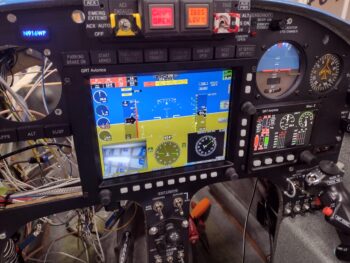
I then turned on the Dynon Intercom and was met with the alarm audio alerts from the AG6 warning annunciators (one for the canopy open alarm from AG6 #1 and the other an IBBS low volts alarm from AG6 #2).  Once I finished booting up the HXr and Mini-X EFISs, I was met with a myriad of EIS audio alarms —since the engine data systems aren’t hooked up (and engine not started).

Clearly these functioning audio alarm outputs are initial indications pointing to good wiring on the audio mixer, intercom, AG6s, HXr and Mini-X.

Pressing forward!