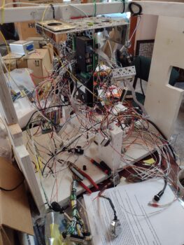
This post covers the past 4-5 days, where I have actually been working some long hours each day on the electrical system…. just hard to grab “action shots” of seemingly endless hours of inventorying and verifying components (relays, inline fuses, micro-switches) etc. that may have been changed out, eliminated or functionally repurposed over all these years as my electrical system has morphed a bit and circuits consolidated in a number of instances.
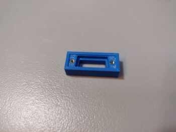
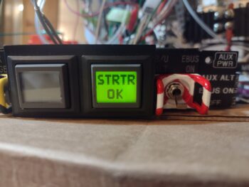
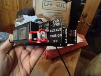
Starting off, I did get the little Push-to-Test button cover glued to the right end of the Warning Annunciator Sub-panel, replete with labels. I did note in this pic the wisp of glue that seeped out and promptly removed it after the photo-shoot (ha) was done.
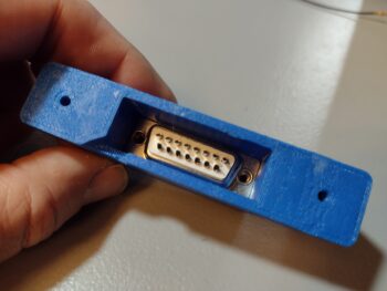
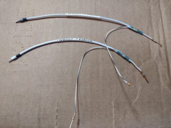
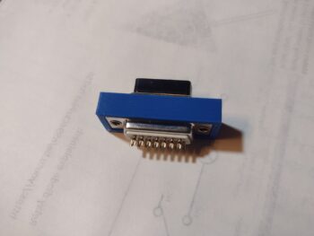
 On the P5 connector positioning to provide a scooch more slack for the control stick cable, I was able to wrangle another ~3/8″ to get a hair more slack, with both sides of the P5 connector mounted in their original configuration. I’m calling that more than adequate and will now focus on protecting the cable from chaffing in the area around the bottom of the control stick. Issue resolved.
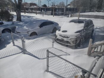
Not shown is that I soldered up the inside-conduit wiring harnesses for the Right wing’s leading edge landing/wigwag light and wingtip nav/strobe light. I did have an issue with the setscrew binding and stripping while installing the nav/strobe light assembly, and have gathered up the bits and tools to resolve that issue (hopefully)… the issue is, as you all may have heard (or are experiencing), the current weather is really darn cold.
Thus, I’ve been holding off on shop tasks until I need to really crank the heaters and do multitude of hours worth of work to justify burning through my Kerosene to heat up the shop to a halfway comfortable working temp.
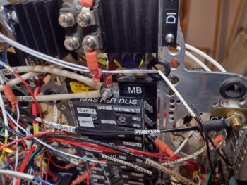
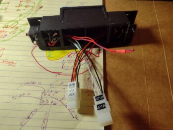
One current and one future capability task I undertook was to connect up my “new” mini-EFIS (MiniUni2) —that replaced my MGL clock/timer in the upper left hand corner of the panel— with the Aviation/MAPCOM data feed out of the GNS-480. This feed enables the CDI screen and GPS waypoint data displays on the MiniUni2.
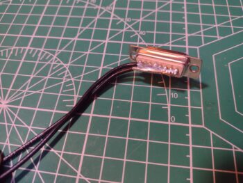
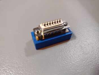
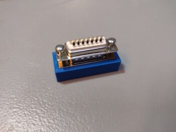
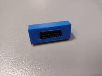
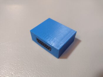
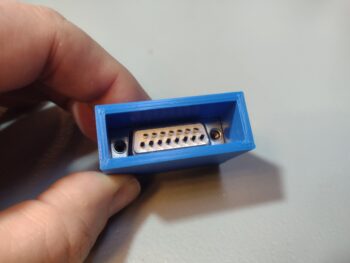
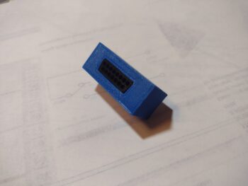
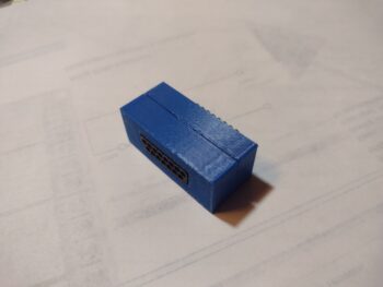
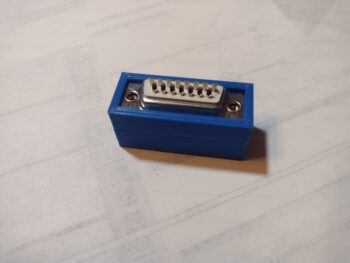
Additionally, since I literally had to create a notch in the case of the MiniUni2 to allow clearance for the outboard bottom corner of the “EFIS vs GPS” (GNS-480) panel switch, I figured I would just tie into this switch for the data feed. The gray D-Sub back shell lower right is to the MiniUni2 EFIS.
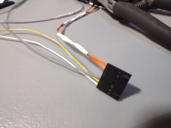
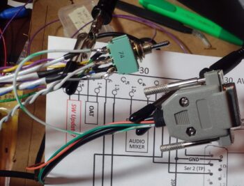 Also on the switch above and tied directly into the GRT HXr EFIS wiring bundle are more ARINC leads to provide for a couple of future capabilities that I’m seriously considering, and much easier to tie into everything now while it’s all exposed and accessible, with a consolidated pigtail to tie into later if I choose to, than to have tear everything apart at a later date… even if I don’t go in any certain direction in the future.
 As I mentioned before, the inventorying and verifying of components and parts, which may have been changed/updated on one or two diagrams, but not on others that denote the same components… as well as ensuring that any re-ID’d or renumbered bits get in their final position and true nomenclature annotated. This includes jacks, plugs, relays, inline fuses, and micro-switches, to name a few.
Then there is the deep dive into each component/system to ensure the circuits are correct both in design and physical implementation, not just on the wiring diagram.
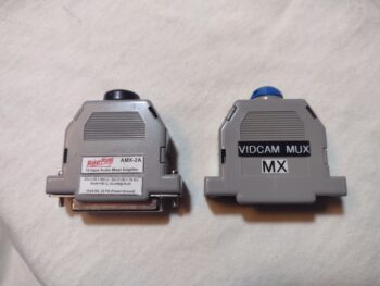
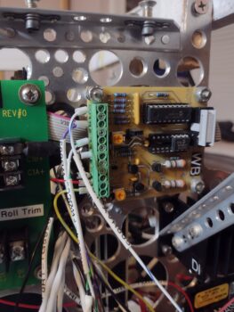
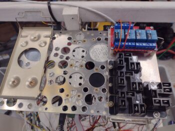
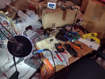
For example, starting in the upper left of the pic below is the AMX-2A 10-channel audio mixer. I had a question on my circuitry since my pin-out didn’t look exactly as was prescribed in the manual’s primary example. I couldn’t find any notes or annotations I had made so I emailed Vern Little, the designer of this little gem, to verify ALL my circuits were good. Within about 10 minutes he emailed me back with a satisfying ALL GOOD (paraphrased)… pressing forward.
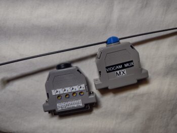
At top center is the wiring and pinout sheet for the Video Camera MUX that came to life through a collaboration with Bob Nuckolls (Wichita, KS), Eric Page (Washington), and Alec Meyers (BC, Canada) based on my requirement to connect more than one video feed into my HXr EFIS, and be able to cycle through the feeds. In the instructions it says that in order to stabilize the video quality and not expose/induce harmful voltage spikes to the board that ALL cameras should be powered from the MUX.
Well… ooops! The wide angle camera in my pilot headrest looking aft is a 5v camera, that I had powered off of the one 12v-to-5v converter I have in play behind the panel. I queried Eric Page on this, asking if I could use an inline “Buck” converter for this one power source to keep it on the MUX’s power feed… he said he has a small PCB device that he designed for his taxiing camera on his Kitfox which is much more electrically quiet than your typical cheap —but noisy— Chinese-made converter, and that he would make one up for me and send it out… after being the ringleader in the Video Camera MUX creation, ginning up the “Deslumpifier” for both me and Marco, the mini-amplifier to allow inputting the correct data signal voltage into my EIS for the Electroair’s timing advance monitoring, and now this?? Eric is truly my electronics Guardian Angel!
I’ll note that I also ordered a number of required plugs/components to allow wiring up the video cameras to the Video MUX.
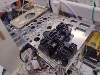
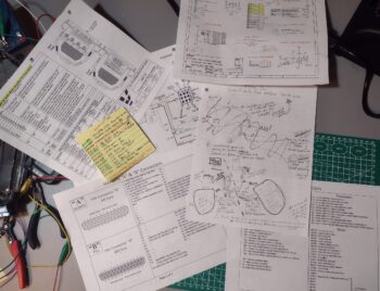 The yellow Post-It pad is me doing yet another inventory of every single micro-switch (aka “snap action” switch) to verify which ones are still in play, which ones have been consolidated and dual-purposed, and which one or two have been replaced with a relay…
Which is pretty much what the chicken scratching page is in the center… although it is my creating a circuit diagram for a relay replacing a regular switch vs a micro-switch.
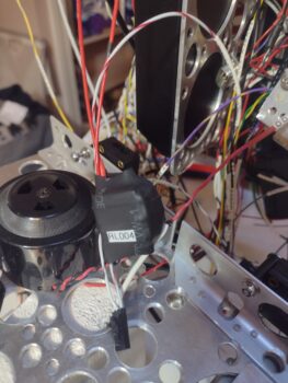
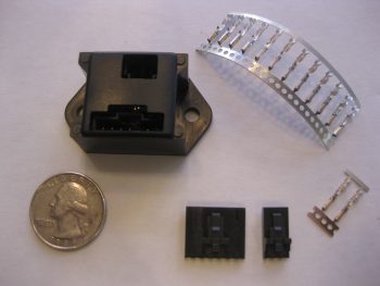
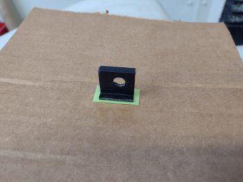
This new relay, RL019, is a DPDT relay that controls two (2) distinct and separate circuits, both reporting the status of the RAM air can’s valve —open or closed— since that info can range from good-to-know to must-act-now to keep possible FOD out of the engine innards.
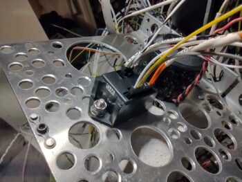
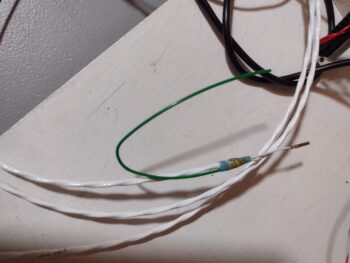
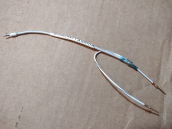
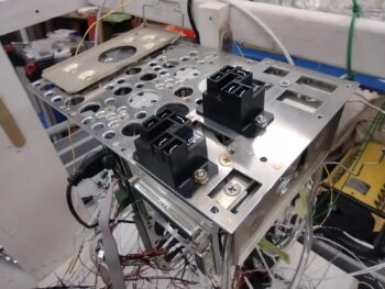
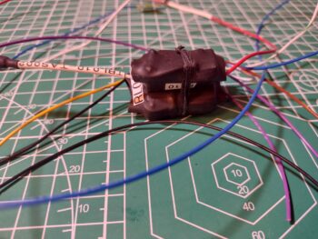
Here is the post-wire soldering to the new Relay 19 (orange) testing to ensure the physical wire solder joints are good as well as the circuit logic. Both were fine.
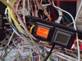
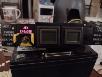
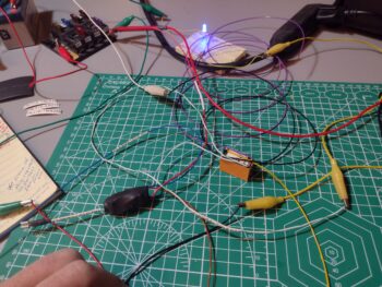 As I noted above, Circuit #1 on Relay 19 is controlled (and powered) by the RAM air valve switch being flipped into the “valve open” position. This powers the relay and the “RAM Air Open” panel Korry indicator light in the row just above the HXr EFIS. This is an informational light only, denoting that the RAM air valve is open… nothing else.
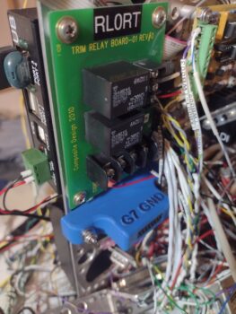
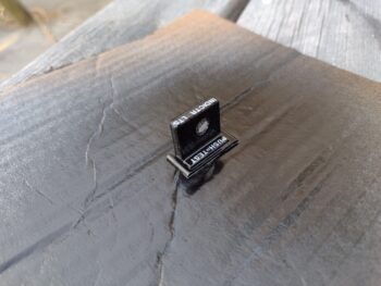
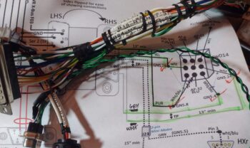
Here we have the wires of Relay 19 wrangled and tied closely to the relay body (pic 1) which then allowed me to heat shrink all the wires tightly to the relay–and label it (pic 2).
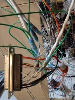
See the short white/blue stripe wire lead between Relay 10 and Relay 19 above?
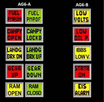
This is the second circuit that is fed in from Relay 10, it itself which is controlled (on/off) via the #2 airspeed switch. If the plane is slower than 90 knots, which generally means in the pattern and preparing to land, then Relay 10 powers that white/blue lead to Relay 19’s second circuit common pin. If the RAM air valve is open via its switch, which in turn powers Relay 19 on, then it closes the Relay 10 feed through the common pin to the NO pin to send power to one of the AG6 warning annunciators with a red flashing “RAM air open” to denote action required in closing the RAM air valve before landing [I would have preferred to use an altitude signal to do this function, but using an airspeed switch based on landing speed profiles was much easier and way less costly].
For ease of mounting on the Triparagon, I then laced the two relays together.
 A closer shot of Relay 19 and Relay 10 secured together.
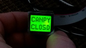
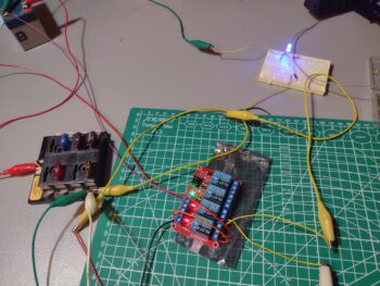
 I do have another circuit I’m testing out to keep the canopy-open warning from blaring out when I have the plane parked and the Master switch on… and I had a 4-relay bank board lying around, so am doing a bit of testing on that to see if some of its unique features might work… still underway and to be determined.
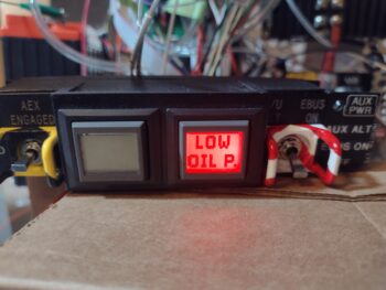
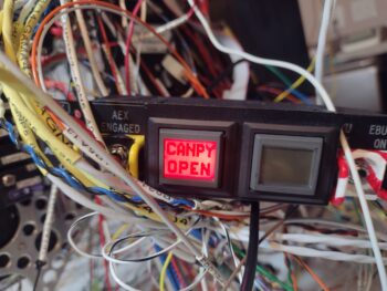
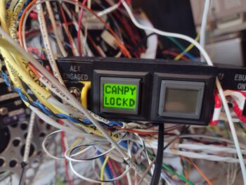
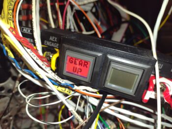
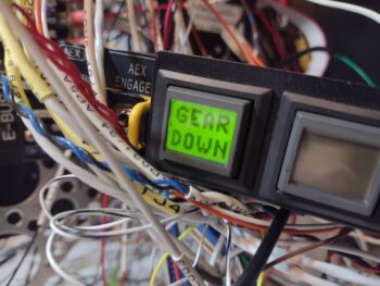
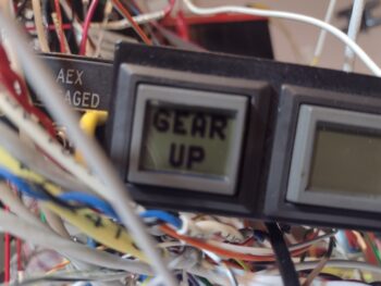
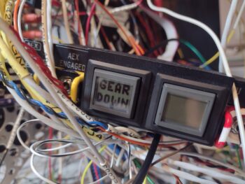
 My next focus will be confirming, verifying, and wiring up all 12 component alarm inputs into the pair of AG6 warning annunciators, as well as finalizing the wiring and pinout of the separate canopy/gear warning system.
Pressing forward!

 Also note the gray wire also attached to NO to report the StarLink’s powered state to the panel indicator light.
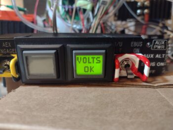
 The instrument panel in our aircraft is of course all about providing us with information, and in that vein both yesterday and today I did a final assessment on my top of panel indicator lights. I’ve got a minor mod going on to increase capacity on my information reporting. I’ll detail that as well once I get into it, but that also included soldering some wires to set up my final schema on those.