Chapter 22 – More electrons

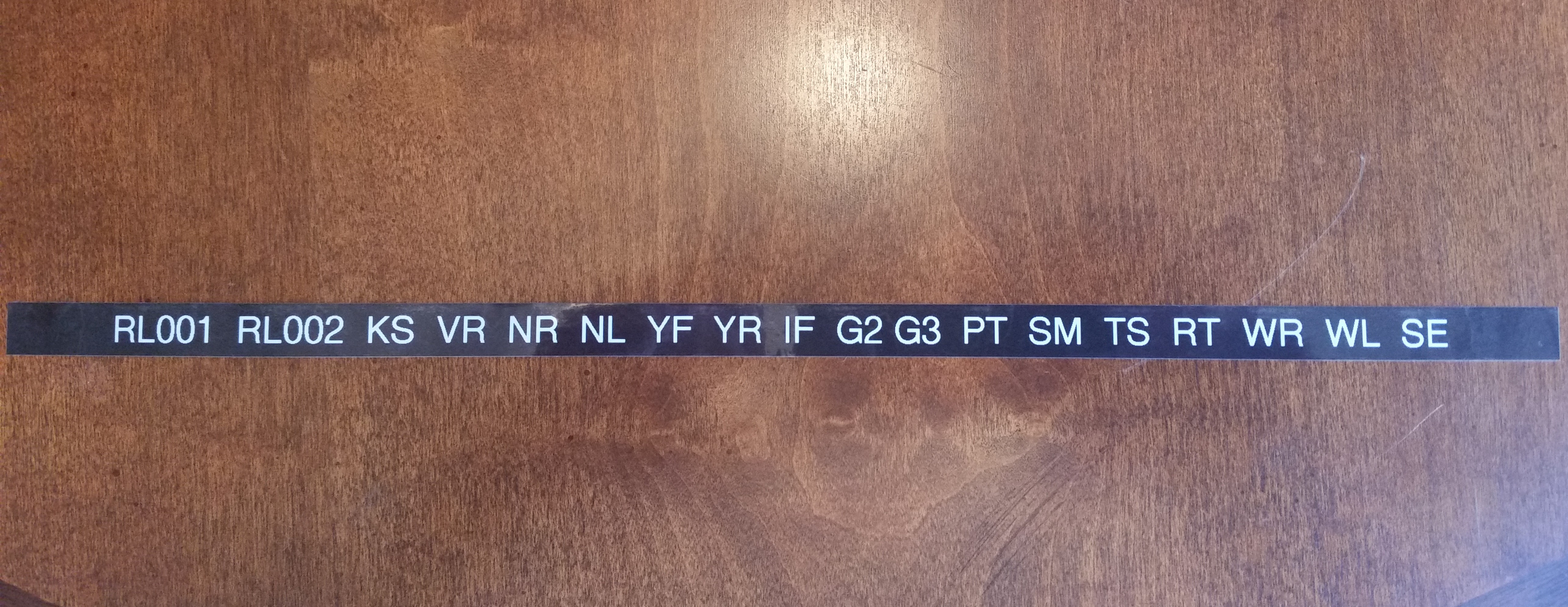
Today was another bust on getting some shop work in.  Between business calls, meetings and knocking out some personal errands, I just couldn’t get some shop time in.  One thing I could do while I was on the phone was make labels for my electrical components.  So I did.

As many of you may know I designed my electrical system so that I have each component identified with a 2-digit code, and then a 3-digit identifier for the pin, wire  or connector.  Combine this with a 1-letter designator prefix that identifies one of 12 distinct areas of the aircraft, and I then have a resulting 6 digit code that tells me exactly where any wire is coming from or going to, and the device at each end.

So as I was on the phone I simply pulled out the label maker and started going through the list of codes.

Electrical component labels

When I got a chance I would cut a few out and label the components that I have close by.  Since I was in a groove at the end of the work day, I simply rolled into digging into my stores of electrical stuff and labeling a large number of them.  I would say I have about 70% of my electrical components on hand labeled.

Since I was deconflicting and updating my electrical component ID list, this segued into my figuring out more finitely each component installation location in the airplane. I pulled out the Electrical Book of All Knowledge, The AeroElectric Connection by Bob Nuckolls, and reviewed it to make sure I was not straying off the straight & narrow path of good electrical practices.  Especially considering that plastic airplanes amplify a lot of commonplace negative issues that crop up in wiring any airplane.

I also reviewed a lot of other builders’ electrical systems, analyzed those, and emulated a lot of good install how-to’s.  I also jotted down some crude diagrams to look at wiring runs, device locations, etc.  This involved digging out a lot install manuals and verifying a fair bit of information.

By working through what I did last night, I really feel that I confirmed and elevated the completion level of my electrical system design from about 75% to about 90%, and with just a few more minor pieces of information, and perhaps a few phone calls, I’ll be really close to locking in the final locations of nearly all my electrical components.


Chapter 16 – Dissecting the throttle handle

My original thought when I acquired my new F-15 throttle handle was to simply test all the individual pins & create a wire map of all the switch circuits.  Well, with a 37-pin cannon plug, that was a little easier in thought than in practice.  After hunting & pecking for a while, I decided that it was time to dissect the throttle handle and see what exactly I was dealing with . . . and I’m glad I did.

I had already made up a pin-out diagram for the cannon plug & numbered each pin.  Since I wasn’t able to figure out the circuits for the switches or visually see them, I clearly wouldn’t know their functioning until I cracked this thing open.

F-15 throttle handle disection

The first thing I saw when I opened the throttle handle up was the flat joystick-style switch that sits on the outboard, front side of the throttle handle.  It took me a while to carefully dig out the potting material & get the wires situated to the point that I could finagle this thing out of there.  It was a very tight fit!

F-15 throttle handle disection

F-15 throttle handle disection

I then began digging out the other top switch from its potting goop.  I identified the wires & listed them by color on another sheet of paper.  I set about confirming their connections by performing a continuity check by placing one side of my test lead on a switch terminal, then at the cannon plug side I would simply swirl the test lead around until the voltmeter rang out.  Then I would annotate it on my diagram.

Dissecting F-15 throttle handle

After I finished the top switch & had all its info documented, I would then spend another 20 minutes or so excavating the next switch from its potting material prison.  Once its leads were exposed, I again performed a continuity check to figure out the cannon plug pins.

Dissecting F-15 throttle handle

After determining the wiring schema for all the switches on the throttle handle, I discovered some key pieces of information:

a.  I am going to completely rewire the switches in this throttle handle.  Clearly these switches are configured for specific discreet electrical components on the F-15, as evident by the myriad of capacitors, resistors, etc. hanging all over each switch.  Plus, there is far more extra capacity with a 37-pin cannon plug than I am going to need to drive my components with the switches on hand.  My initial thought is that even a 23-pin plug will give me plenty of future scalability.

b.  I’ll be removing the pistol-shaped switch that engulfs the entire interior left side of the throttle handle.  It may provide more capability when linked to specific F-15 systems, but in my case it only offers me a single-position momentary on.  It takes up a lot of real estate and it’s heavy, accounting for almost 20% of the current weight of this handle.  If I get rid of this switch by replacing it with a nearly externally identical Otto switch (with much smaller internal guts), reduce my throttle handle wiring harness by nearly half the wires, and use a smaller plastic AMP connector, I think I could reduce the weight of this handle by about half (about 0.65 lbs).

For those of you that are curious about the current throttle handle switch functions, they are listed below this pic in order starting at the top right-hand switch (flat grey) moving CCW.

F-15 Throttle Handle

1.  Grey flat joystick style: single momentary on (TBD).
2.  Black push button: PTT – single momentary on.
3.  Black push button: single momentary on (GTN650 remote or Trio AP fuel data)
4.  Metal china-hat toggle: ON-OFF-ON (possibly air brake)
5.  Black push button: DPDT dual momentary on (TBD).
6.  Grey-capped toggle:  3-position (broken lead/functioning TBD… ON-OFF-ON?)
_________________________________________________________________________

Also, as I mentioned in my last post, for those of you that are curious about the size & fit of the F-16 throttle handle, I shot a couple pics to show what I was talking about.

F-16 Throttle Handle Comparison

Not terrible at all, but definitely takes up more space than I’d like it to inside the Long-EZ cockpit.

F-16 Throttle Handle Comparison


VSWR what?!

In the December 2013 edition of Kitplanes magazine I found yet another useful piece of information, and like so many other times during this build, it came a year or so too late. The article was written by Jim Weir–maker of many canard antennas–and discussed checking the VSWR (Voltage Standing Wave Ratio) of each antenna before burying it under the skin of a plastic airplane such as the Long-EZ, at which point if you have a problem . . . well, better think up some good solutions!

Jim recommended a MFJ-259B Antenna Analyzer to check the VSWR on each antenna to ensure they were good.  Again, my antennas already being installed, I still wanted to check them to A) know if any had a VSWR too high to count as good, and B) pick the best between the COM antennas for COM1, and the best between the NAV antennas for NAV1.  The goal is a VSWR ratio less than 3:1, because anything higher is a lot electrical energy traveling back along the OUTSIDE of your antenna coax cable to the transmitting device (ie, radio), which will drive your available Tx wattage to unacceptably low levels and could damage your transmitter in the process.  In addition, as with so many other units of measurement in the weird & wonderful world of electrons, VSWR readings are logarithmic.  Any increases above a 1.5:1-to-2:1 ratio and things start getting real hairy real quick!

I of course started hunting around for a good, used antenna analyzer at an acceptable price anywhere I could find one.  That pretty much drove me to eBay, where I picked one up for about half the price of a new one.  And thar she be below.

MFJ-259B Antenna Analyzer

The only problem with my newly won prize (which I actually bought a while ago), was the antenna cable adapter that came with it.  These analyzers can be used for checking any antenna and are common in the HAM radio world, so perhaps the antenna cable adapter that came was used for something even more exotic by a HAM radio bubba.

Old Connector ???So although I didn’t know what the mystery adapter was used for, I did know that to check the BNC connectors used on the Long-EZ antenna cables that I would need a BNC adapter for the antenna analyzer.  So, last week I ordered a couple of them, one male and one female, and I got them in today.

New BNC connectors M & F

You can see the new BNC antenna cable adapters on the right, and the old one on the left. Below is a shot of one installed on the antenna analyzer.

It fits!

Since the weather is still too cold to economically heat my workshop for glassing, I plan on terminating all my antenna cables with BNC connectors and then checking the VSWR of each one with this MFJ-259B antenna analyzer.

Chapter 21 – Capacitance Fuel Probes

This afternoon I was able to get a hold of Master Canardian Nick Ugolini and order a set of his Capacitance Fuel Probes.  Nick designed the probes himself to be used in canards and to link up to Princeton Fuel Probe electronics to provide high quality fuel reporting to EFISs, etc.

Chap 21 - Capacitance Fuel ProbesAt first I resisted the idea of fuel probes since I already have Vance Atkinson’s fuel site gauges and will be using a fuel flow sensor.  But considering that these are just a few ounces a piece including the electronic control boxes, I figured knowing my exact fuel quantity for a total weight penalty of well under a pound was worth it.  In addition, I had just read too many reports extolling high praise for this system to ignore them all and not pull the trigger on a set. (I pulled the pics below off of Nick’s blog):

Chap 21 - Capacitance Fuel ProbesAnother motivating factor for installing these probes early on (i.e. during the build) is that since I’m gearing up in the planning and R&D of my strake-building, it just makes sense that they’re a heck of a lot easier to install now during the initial strake construction vs. changing my mind and installing them after my strakes are all closed up.  Now, that being said, they actually don’t look to be that difficult to install after the strakes are built, but anything I can do to avoid introducing potential contamination–in the way of bits & chunks of foam & glass, etc–into my fuel system is worth doing early on.

Chap 21 - Capacitance Fuel Probes


Chapter 22 – Instrument Panel Ongoings

Chap 22 - Garmin G3X Touch

After squawking about the new Garmin G3X Touch being too expansive for my wee panel, I decided that I should thoroughly investigate it to ensure I wasn’t missing anything important.  So this past weekend I again built a matrix to compare all my EFIS options to ensure that I’m getting the best capabilities, cost benefits, and of course weight efficiency out of my EFIS that I possibly can.  Thus, I did a runoff betwixt the new Garmin G3X Touch, threw the close-sized GRT HXr 10.4 back into the mix, the GRT HX 8.4, and GRT HX 6.5.

Chap 22 - GRT HXr 10.4 EFISChap 22 - GRT HX EFIS

I then began to tally up all the weight, cost & current draw of all the components required to give me the capabilities I’m looking for in an EFIS system.  Something to note that in all of these configurations is that the second-screen MFD and back-up PFD is the GRT Mini-X.

Chap 22 - GRT Mini-X EFIS

I was surprised as I tallied up the prices that the cost difference between the Garmin G3X Touch and the GRT HXr was less than a grand.  As I trudged along in looking up component weights, and with things still looking comparable between the two systems (of course giving a slight performance edge in touchscreen simplicity to the Garmin), I hit a fairly significant snag.  It appears that Garmin’s remote transponder is a robust bubba, weighing in at over 3.4 pounds with an installation depth of over 11 inches. The weight on this one transponder helped get me back to reality, realizing that I was comparing the big heavy guys, when once again I was getting plenty of capability with the smaller, very capable “little guy” EFISs that were much lighter and offered much more panel space … and thus configuration options.  So once again, although tempted by cool colors and touchscreens, I dumped the big EFISs to return to smaller, lighter and more efficient.

One thing that came out of my EFIS comparison, was that I took a hard look at my allowable space BEHIND the instrument panel.  I pulled out the plan’s A-pages to measure out clearances and I had a true Doh! moment.  Albeit initially (Fall 2012) I had been verifying clearances behind the panel with cardboard mockups, since then I had been rearranging, adding, removing and modifying my avionics/instruments with apparent reckless abandon!  The result was that I was placing components in position on the front panel with assumed clearance behind the panel.

To remedy my ways, I gathered the physical data for the displays, avionics, instruments and components all going into the panel.  I clearly needed to deconflict my behind-the- panel space requirements to match what I could have on the front of the panel.  I will say that I attribute this epiphany in part to Nick Ugolini since I found while reviewing his blog that he had run into this snag while redoing his instrument panel.

A significant focus in this effort is of course the area immediately behind the lower right side panel, since the elevator control rod must have free reign in its movements.  I had stacked up my GNS430W/GTN650 over on the right side, having failed to verify it’s clearance with the elevator control rod, and then even added a couple of other rather deep instruments to boot.  I’m glad I found it now, but I admit it was not the most optimized planning on my part.

The result of all this was a trip back to the proverbial drawing board.  I got out my cardboard cutouts and begin putting all the “new” puzzle pieces in place.  The result is something along the lines of this:

Chap 22 - Instrument PanelAgain, I will make note that this is still a work in progress, but at least now I am very cautious about my specific clearances behind the panel.  In the back of my mind I thought I was doing this, but pulling out the actual plans verified and confirmed how little space there actually is behind our panels in these birds.  And of course we all know what assumptions get us!

Build on!


Chapter 22 – Behind the Scenes

Today I finally pulled the trigger on some behind the scenes–or rather, behind the panel–components.  While some EFIS systems like Garmin make use of Micro-SD cards for updates, etc, GRT uses USB for software updates, system backups, and historical logging of flight and engine data.  In addition, GRT’s remote BlueTooth capability and the Radenna SkyRadar-DX ADS-B both tie into the system via USB.  To have enough capacity, including having a panel-mounted USB jack, I needed to acquire a USB hub and the remote panel jacks that allow me to simply plug my USB stick right into the panel.

Chap 22 - 4-Port USB Hub

There are a couple industrial strength USB hubs that GRT recommends on the advice of a number of builders that have trial tested these devices.  I opted for the StarTech 4-Port USB Hub because it was significantly cheaper than the other recommended 4-port hub, it got great reviews on Amazon, and its configuration.

Chap 22 - 4-Port USB HubAs for this hub’s configuration, you can see in the pics above that ALL of the inputs for both power and data reside on one side of the hub.  The other recommended hub had inputs on both sides of the hub.  In my opinion, having all the inputs on one side makes it easier in both mounting the hub and in managing the cabling & wiring.

As I mentioned above, in order to tie both the main GRT EFIS and Mini-X EFIS’s rear panel USB ports to the instrument panel in the way of panel-mounted USB jacks, I ordered one cable per EFIS that has a standard USB plug on one end and screw mounted female USB jack on the other.  Obviously this will allow plugging the USB stick in at the panel and give me the same capability as if I was plugging it into the back of the EFIS box.   Below is a pic of the panel side of this cable, and a diagram showing the mounting specs for the jack:

Chap 22 - Panel Mounted USB CableChap 22 - Panel Mount USB


Chapter 22 – ADS-B IN Receiver

I have to say that in addition to Insight, the company that makes the Strike Finder, I’m so far quite impressed with the folks at Radenna who offer a line of SkyRadar ADS-B Receivers.  Back in early January when I purchased their latest ADS-B receiver, the SkyRadar-DX, they stated they would be shipping on March 20th, and they did exactly that!

The DX model is different from the previous SkyRadar ADS-B receiver models in that it offers WiFi (Apple, Windows & Android compatible) with attitude indicator (PFD) information displayed over the WiFi channel.  Of course the standard ADS-B info, traffic and NEXRAD weather, is transmitted to wireless devices as well.  Like the SkyRadar-D, one nice thing about this unit is that it receives both 978 and 1090 MHz signals.

The wireless is a bonus since the primary operation of this system will be via a USB connection between the ADS-B receiver and the GRT EFIS, so all ADS-B info will be available on the EFIS screen.

Also, remember that the ADS-B receiver is only one half of the ADS-B equation, in that to fully utilize all that ADS-B has to offer a Mode-S transponder must be used as well.  I’ll be using Trig’s TT-22 mode-S transponder that will be remotely mounted behind the panel and controlled through either of my GRT displays.

So without further ado, here are some pics of my new ADS-B Receiver.

Chap 22 - SkyRadar-DX ADS-B ReceiverChap 22 - Radenna Dual-channel ADS-B ReceiverChap 22 - SkyRadar-DX ADS-B ReceiverChap 22 - SkyRadar ADS-B Antennas & GPS PuckChap 22 - SkyRadar ADS-B Antennas & GPS Puck

To watch a short YouTube video showing the setup of the SkyRadar-DX ADS-B Receiver click here.
For a longer 10 min video showing the moving map & traffic features click here.
To see the SkyRadar NEXRAD weather in action check out the short video below:


Chapter 22 – Fuel Fume Detector

I got the idea for installing a fuel fume detector from the RV guys over on the VAF forums. It makes sense to me especially in a plastic airplane like the Long-EZ where almost the entire fuel system resides in or around the cockpit.  I definitely want to know if I have any hint of a fuel leak as soon as absolutely possible.

There doesn’t seem to be many fuel vapor sensors out there on the market, and a few of the RV flyers swore by the Xintex Fireboy Fuel Fume Detector.  Now, these are actually sensors used in the boating community to sense any problems in their engine compartments.  So I bought one off a guy who recently installed it in his boat, but then decided to swap his boat engine out with a diesel motor.  Thus, I was able to get it much cheaper than what they sell for at the normal boat supply retailers.

The pics below show the control head face, the vapor sensor and the connecting cable between the two:

Chap 22 - Xintex Fuel Fume Detector

Chap 22 - Fuel Fume Detector SensorChap 22 - Fuel Fume Detector CableYou’ve probably noticed this on my instrument panel pictures.  I’m not sure if I’ll actually mount it on the actual panel or not, but I normally mock it up to see if I will have space for it if I do decide to panel mount it.


Chapter 22 – Strike Finder Update

I received the Strike Finder system back from Insight after they upgraded the display to a bright LED one.  Quite a contrast (literally) from the old style plasma display.  They also did a complete checkout of the system, including both the control head and the sensor.  In addition, I had them throw in a new cable that links the control head to the sensor.

Chap 22 - Strike Finder

Note in the picture below all the re-certification documents for the individual components.

Chap 22 - Strike Finder

I have to say that the folks at Insight are a great group of people that are both extremely pleasant and very helpful to work with.  They explained everything in depth, laying out all my options in a very clear and detailed manner.   I am very impressed with this company.


Chapter 22 – More Instrument Panel

Thought I’d show a couple more of my Instrument Panel machinations.  The first one below shows the real deal with the iPad Mini fired up with FlyQ EFB from AOPA, and my Android phone with the GRT app showing the Bluetooth wireless COM radio control function.

Chap 22 - Instrument PanelThe next picture shows my throwing the big 10.4″ HXr screen PFD back onto the panel to assess how it will fit.  A number of other items are on the panel to see if they fit, not necessarily in the location they’ll end up.  I also swapped out the Garmin GNS430W with the Garmin GTN650 (my actual panel is about 0.7″ higher than this one at the top middle, so even thought it looks like I’ve run out room, there still some more wiggle room left up along the top curve).

Chap 22 - Instrument Panel