Chapter 22 – Light switches wired

First off, this blog post covers the past few days…  which were a bit busy.  Jess and I spent later afternoon into Saturday evening prepping for, and then attending, the EAA holiday party/potluck, which was a good time had by all.

I was able to get most of the landing and wig-wag light switch wired up in the couple hours I had available to work on the plane, finishing it entirely the next day.  I then wired up the Nav/Strobe light switch to finish off the switch side wiring for these 2 light switches (the power and ground connections still need terminated into the appropriate busses).

I installed the P5A connector below its bracket (vs on top) with 1″ spacers to assess providing a bit of slack to the control stick cable.  It looked fine until I received the battery for the ELT remote switch, and installed both the battery and the switch (temporarily… not screwed) into place.

As you can see, the ELT remote switch intrudes into the space of the P5 connectors —not enough clearance— so I need to go back to the drawing board and consider one of my other options.

I also hooked up the Landing Brake ground wire (middle of pic – vertical) and the control wire (labeled) that is terminated into the P4 connector (throttle switches’ wire cable).  Both these wires tie into a pair of wires that can be seen just above the top outboard corner of the ELT, and together make up one half of the circuit to the Landing Brake switch on the throttle.

I’ve been having an issue with my soldering iron tip giving me grief during splices, etc, so I did a multi-day, multi-hour deep dive on that to order the correct tips and hone my soldering Kung-Fu skills moving forward.

Day 3 I received my order from Steinair, including a new 5A circuit breaker to replace the one that I destroyed with such manly power installing the screw on the wire tab (ha!).

As you can see the new one is in and wired up, with no issues thus far.

A couple nights ago I copied the wiring circuits from the wiring diagrams and verified the circuits for the Auto Gear Extension system and SD-8 Backup Alternator and E-Bus only switches that both reside in the Warning Annunciator Sub-panel.

In prepping to wire up those switches (thus my critical emphasis on a well-working soldering iron) I drilled/bored out the holes a little on the right side to install the Push-to-Test button for the row of On/Off LED indicators just above the center EFIS.  It took a little persuasion, but for the most part the push-button switch cooperated and went into place (pic 1).  I then solder-spliced (after cleaning the solder tip with a new compound) wire extensions onto the switch leads to allow the wires to be run through the instrument panel fairly easily (pic 2).

After hauling all the tools into the house for a few rounds of soldering to finalize as much possible on the Warning Annunciator Sub-panel and right (which I’ll work tomorrow), I called it a night.

Chapter 22 – Dim(mer) witted!

I started out today by wiring up and then installing the Pitot Heat switch.  I then focused on getting the two (2) dimmer switches installed, which required me getting back into their respective install manuals to get the job done.  Those required wiring up as well.

The new switches will require the Tri-Paragon to be installed to truly finish up the wiring, as with nearly all the switches on the panel.

I spent a good hour organizing, cleaning up and deconstructing my wood panel mockup in preparation for the Tri-Paragon to soon be installed in the bird.  Obviously having a temporary functional mockup meant that I had to run a bunch of temporary power and ground wires.  Thus, after pulling those off the mockup, I repurposed them on these Dimmer switches for both the power and ground —replete with already attached FastOn terminals (power) and D-Sub pins (ground).

Here we have the front side of the panel showing the Dimmer switches installed (and the orange wires peeking out from underneath for the Pitot Heat switch.

It was quite chilly today and my shop heater ran out of Kerosene in the mid-afternoon, so I ran down to get some more.  While out I stopped at a small hardware store that has a good “Aviation Hardware Department” <wink>.  I grabbed some 1″ spacers and SS screws to test out installing the P5A connector lower to provide the control stick cable another inch or two of slack.

The green tape on the panel is where the ELT Remote Switch mounts.  The battery for that should be delivered tomorrow, at which point I’ll install it and verify clearances between the combined P5 connectors, the ELT Remote Switch and everything else.

A backup option that I have for providing the slack I want for the control stick cable is to convert the P5 cable connector to a D-Sub connection, which would be much smaller and easier to fit into such a busy corner of the panel.  But before I lop off all those CPC pins and sockets I want to do my fairly quick due diligence and see if these current connectors will fit into this corner melee.

Inching forward…

Chapter 22 – All about the Bus…

The BATTERY BUS that is!

I finally got my wire label heat shrink cartridge delivered today and quickly pressed it into service to make 2 batches of labels, a number of which I used immediately.

I got a late start in the shop today, and even when I got out there the physical space that is inside my panel area pushed me to call an audible regarding my to-do list.  I had planned on knocking out the top pair of switches (landing and nav/strobe lights) on the center strut of the panel to all my big switches knocked out.  But after assessing the space, I realized I would be making the install of the lower switches and dimmers quite a bit more difficult access-wise and visually.

I decided to start on the lower triplet of switches (Pitch Trim Master, Pitot Heat, and IBBS Master) and work from the bottom up.  The Pitch Trim Switch is currently hardwired to the TCW trim system unit on the Tri-Paragon, so will not be installed until the Tri-Paragon is installed.

The simplest of the two bottom switches left was the IBBS Master power switch, so I targeted that.  However, it had some required prerequisite tasks (par usual) before I could install it: I had to route the wires from the nose aft.

Sitting about the #4 slot on my to-do list for at least a week, which keeps getting squeezed out with new tasks, was the installation of Adel clamps on the NG-30 upright (aka “goal post”) on the aft side of Napster bulkhead (just above/inboard of the Battery Bus) and in a few spots on right side of the NG-30 cover.

Ahhh, but running the wires through the Adel clamps had its own prerequisite tasks (see why I’ve been kicking this can down the road?!): collecting up ALL the wires —to ensure proper Adel clamp sizes— which entailed A) finding them all, B) extending the short wires to make the journey through the Adel clamp “gauntlet” and C) terminating wires coming forward from the panel area to connect to the Battery Buss (plus simply organizing the wires in their appropriate bundle grouping).

I started by solder splicing a length of green/red striped wire to the Relay 18 control wire (upper center of pic).  Later I had to extend the white signal wire of the CS6 ammeter that reports panel current to the HXr EFIS.  Next was rounding up and routing the Landing Brake power wire to the Battery Bus as well as the cigarette lighter charger at the right base of the panel strut (both terminated middle right of the Battery Bus).

Once these wires were terminated, heat shrank, etc. and installed into the Battery Bus, this completes the Battery Bus component wire population (not a bad milestone to reach!).

I then spent the next 2-1/2 hours routing/rerouting, zip-tying, sizing/installing Adel clamps a low bundle of wires and top bundle of wires down the right side of NG-30 and its cover.

I still have a couple of straggle wires that will need extending (or terminated to its mate on the Tri-Paragon) and there is a possibility that I may have to swap out the big grounding cable that connects the “Forest-of-tabs” ground bus on the Tri-Paragon to the battery’s negative terminal (it may be just an inch too short).

Here we have another shot of newly corralled wires down the right side of the NG-30 (pic 1) and from the F22 leghole looking forward at the Battery Bus (pic 2).

The convergence point of the P2 connector, upper and lower wire bundles coming aft is a single Adel clamp just forward of F22, about an inch up from the very aft NG-30 side plate, but actually on the NG-30 cover.

As I’ve labeled this pic: Yep, that’s a lotta wires!

Don’t forget the IBBS master power switch… which I finally got to nearly 4 hours later!

Yes, now that the IBBS power wire was routed up to the aft edge of F22, I could better ascertain the required wire length since clearly it terminates on the switch itself.  I soldered the IBBS power wire to the switch, and then rounded up, cut and soldered a black ground wire on the other switch terminal.  The label for this ground wire is on the list and will be printed with the next batch and applied then.

Tomorrow I plan on installing the Pitot Heat switch and the 2 dimmer switches above that.

I spent about 45 minutes on my last task of the evening which included installing the battery, which BARELY fit into the battery compartment… it was a struggle and I wasn’t sure if it was going to fit with the IBBS AND the main bus power and ground cables coming in/out the top of Napster.

My main reason for installing the battery was to get an exact recon on the black ground cable that goes to the Tri-Paragon ground bus.  Again, it will be very close on if it fits or not.  And to be clear, this is a repurposed cable that I original bought from B&C, and then decided not to use it where I had originally intended it for (as in, I didn’t cut it to this length, just trying to make it work if possible).

Again, another VERY late night… but slowly getting there.

Pressing on!

Chapter 22 – Big 3 switches wired

I’m not overly happy with the somewhat remote locations of my main and endurance busses on the TriParagon.  I didn’t know what I didn’t know starting out so many years ago, and now with the nose enclosed, nose hatch installed, canard installed, etc. I can see that finding a fuse that has popped, admittedly rare as that is once the systems are dialed in, will at a minimum require a mirror, and perhaps even a flash light.  So I did a good amount of assessment on that issue, with 3D printed footprints of the busses to assess more optimum locations, and an assessment of wire flow, accessibility, etc.

After that exercise, I finally got out to the shop, where I spent nearly 4 hours finalizing all the wiring on all but one post of the circuit breakers, and on all of the Big 3 switches in the lower right side of the panel.

Now, see the green tape on the circuit breaker below the row of Big 3 switches? That was the 2nd to the last final wire I was installing onto the circuit breakers.  I couldn’t get the best angle with my Phillips screwdriver, so I used a larger flat tip.  Well, giving it a firm push down as I installed the screw —as I’ve done with all the other circuit breakers— the tab gave way and the bottom of the CB cracked with a couple of pieces of plastic falling onto the floor of the bird.

Yep, 5A circuit breaker CB000 is no muy bueno.  Este es muerto (excuse my hack Spanish: it’s no good and it’s dead).

Back to my busses for a minute… I texted Marco for pics of his busses.  In our discussion, he pointed out the “Lit when blown” ATC fuses to help with ID’ing a blown fuse in the nether-regions of the nose.  I had already decided on those and had them on a list of items to buy from Steinair… and now I just added another item: the 5A CB.  With that added, I finalized my order and pulled the trigger late this evening.

Lastly, see those blue 3D printed caps on the unused switch top tabs on the middle switch?  I drew those up in just a few minutes in CAD, guessed on all the dimensions and thought I’d have to do another version or 3 to dial them in, but they fit nice and snug the first try.  I have another batch printing and will cover all the unused tabs on my big switches, to minimize any hand impalements while working behind the panel, any errant wires or inadvertent grounding, and simply to better assess circuits on those switches.

Back at it tomorrow.

Chapter 22 – Function over form

… at least for the time being.  I say this because my urge is to overhaul the configuration of my electrical components situated on the Tri-Paragon, but that will have to come later after I get this bird flying.

This post covers the past few days… yes, the electrical system install has been a longer, slower slog than I prefer.  A lot of labeling, cross-checking and mundane work of pulling wires, soldering, terminating connectors, heat shrink, wire management, etc.

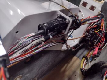
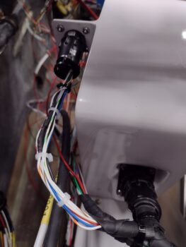
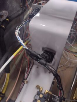
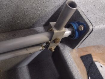
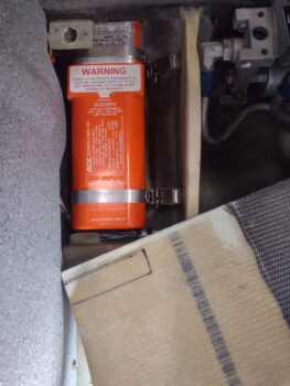
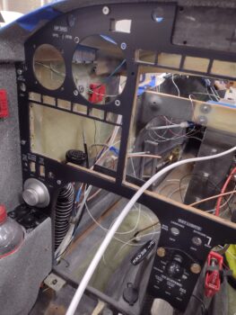
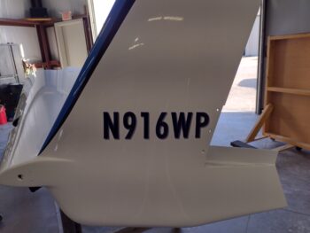
I started off today by cleaning out the mounting holes in the right side top tab on the NG-30 cover.  I then installed the forward P2 connector, which would be identified as P2A, with the A designating the connector side closest to the nose.

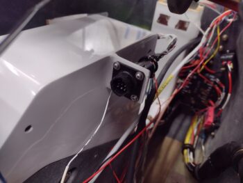
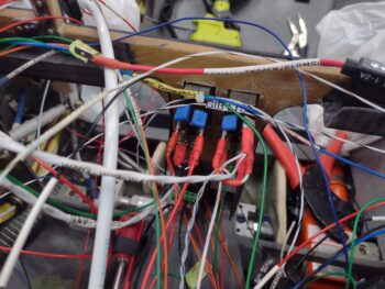
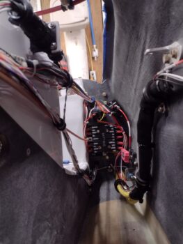
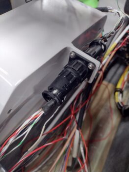
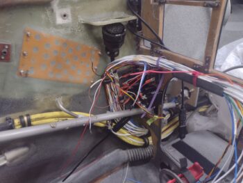
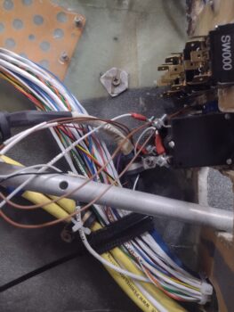
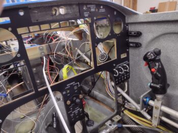
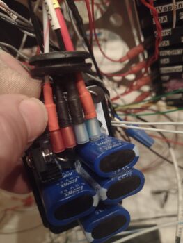
Here we have a shot of the installed P2A connector from nose looking aft (pic 1), and after I installed the P2B connector… AFTER I spent about 1.5 hours finalizing its configuration with terminating sockets on wires, labeling them and verifying the circuits with my wiring diagrams (pic 2).

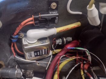
My next goal was to get the final circuit breaker installed, which is the “NAV/GPS” 5A circuit breaker for the Garmin GNS-480.  Technically it was already installed and operational, just on my panel mockup in the house.  Thus, some DIS-assembly was required.

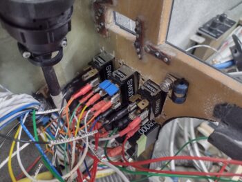
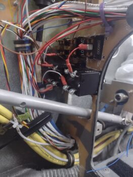
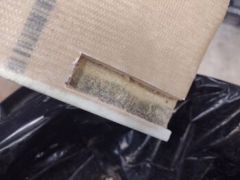
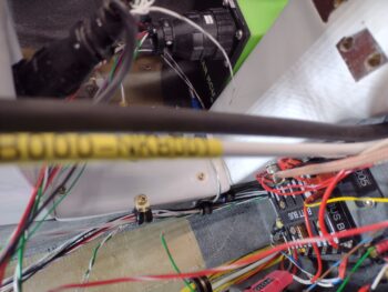
On the first lead coming off the circuit breaker I had to break open the “Deslumpifier” and pull the hot lead out of it (the one at the tip of my thumbnail).

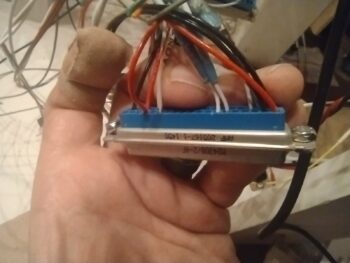
I then had 2 more power wires to pull off the main D-sub connector that connects to the back side of the GNS-480 unit.

After a quick cleanup of the circuit breaker, into the bird’s panel it went.  I then used a 14mm socket to do the final tightening on all the circuit breaker nuts to ensure they were securely mounted.

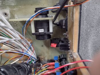
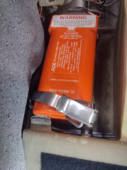
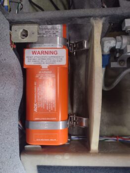
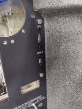
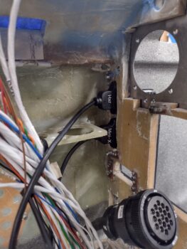
After some final “engineering” on the circuit for the StarLink Internet Antenna that will be going into the nose, I soldered up the leads of the mini-switch (sw017) and then mounted it just adjacent to the left sidewall in the lower left area of the panel.

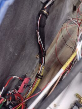
I finished off the evening doing an inventory of all the wires that started or ended in the nose battery compartment and the battery buss just on the aft side of the Napster bulkhead from those wires in the bundle from the aft side the bird, the circuit breaker cluster, or the Big 3 panel switches… all on the right side of the panel.  Instead of running these wires in to the center, then forward, the back outboard, I decided to simply piggy back off the big wire bundle already transiting down the right sidewall of the nose.

The next morning, with about a half dozen wires identified, I got to work.  The first wire was from the bundle and comes from the hell hole.  It disconnects the TCW Tech IBBS from charging if the main alternator is offline and I’m on SD-8 backup alternator power.  Obviously this terminates at the IBBS in the nose battery compartment.

The next wire was the 20 AWG black ground wire from the Master contactor (in the nose) to the Master switch.  When the Master switch is flipped on this wire goes to ground, which fires up the Master contactor.

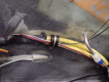
Another significant wire of note also comes from the aft end of the bird in the bundle that connects the electroair coil pack directly to the battery buss on a 10A fuse.  This was one of those head scratchers with me asking, “Why did I do that?” since I ran an 18 AWG wire.  In my mind I knew that the specs supported it, but later I couldn’t find them in any of my notes or emails.

The next morning I called electroair to figure out why I used an 18 AWG wire vs a 16 AWG or bigger.  The tech said that the average load was less than an amp… ok, makes sense why I used the 18 AWG.  He then said the initial inrush current could be as high as 5 amps.  Ok, 18 AWG still plenty in my book.

BUT…

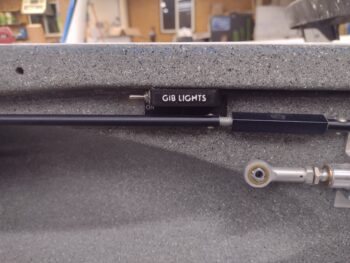
they recommended a 16 AWG wire (again, as with GRT, I’ll note this is NOT stated in the installation manual).  He said if the wire was buried that 18 AWG would most likely have no issues (with Tefzel wiring, this I believe wholeheartedly).  I told him I would meet him more than halfway, since I knew in my mind I could most likely get a 16 AWG wire from the nose to the area just in front of the GIB control stick.  Further aft would be a MAJOR PITA and I just didn’t believe it was called for….

If this were a single seat bird I would have left the 18 AWG wire and pressed forward, but since I have that back seat I felt that I should follow electroair’s guidance as best able to optimize passenger safety by swapping what I could with 16 AWG, which was about exactly where I figured: just forward of the GIB control stick on the sidewall.  This leaves about 4-5 feet of 18 AWG, which is simply not going to flinch at a 5 amp inrush current, let alone less than an amp sustained current.  So final configuration is about 2/3rds 16 AWG and 1/3rd 18 AWG wire.

And that folks, is how I started the first 2 hours of Day 3: swapping out the majority of the 18 AWG wire for 16 AWG.

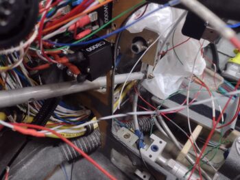
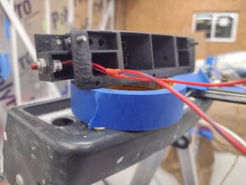
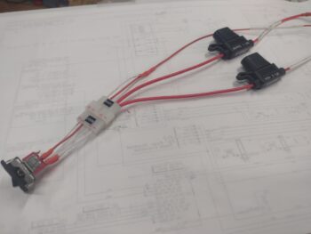
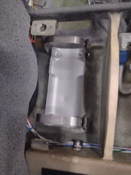
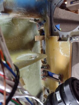
I then spent a bit of time on the EFII fuel boost pump.

For starters, I used some Simple Green and a scrubbing pad to clean it up a good bit.  I then spent over an hour verifying the circuitry (which I simplified), improvising more wire labels (I burned through my wire label cartridge and the new one I ordered hasn’t been delivered yet),  pulling the indicator light wire off the panel mockup to be terminated into the bundle and assessing exactly how the wire runs would go in such a tight confined space (while avoiding the sharp corners/edges of the pump).

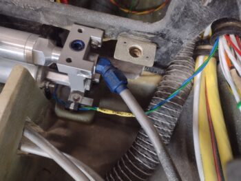
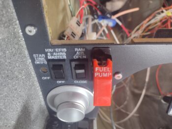
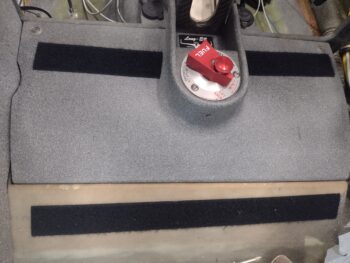
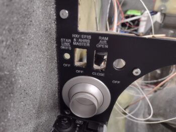
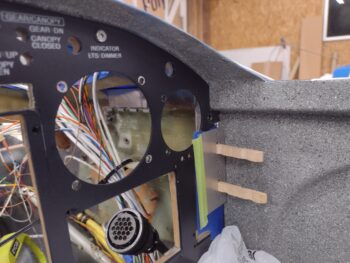
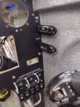
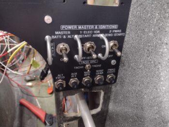
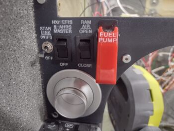
I then ran the fuel pump power wires up the right side bundle and then crossed them over to the left side switch (very bottom pic below).  And with that… Voila! Both my fuel pump AND all the lower left side switches on the panel are wired up and installed.

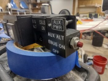
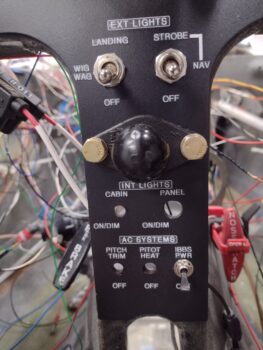
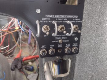
Before I show the last panel pic, as a reminder, here is the GIB light switch control panel.  As the my descriptor strongly infers: it controls ALL the lights in the GIB area.

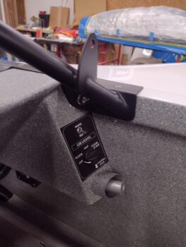
However, my GIB (as in Gal in Back) is prone to fall asleep.  And if I need those lights off for any reason, I have the Master power switch to all of them on the left sidewall just under the longeron.

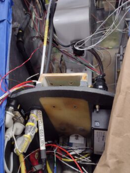
With all that info in hand, here we have the Fuel Pump switch (sw009) wired up, the StarLink switch (blue) near the sidewall, and we have a green (12V+) and white/black wire at the top of the pic (GIB lights Master switch) that is now connected to the wires coming from the right-side bundle for the GIB light control switches. 

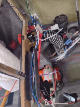
Not shown is that I solder spliced the SD-8 control wire to take the IBBS charging circuit offline when the SD-8 is online.  Out of 8-10 amps available when on SD-8 power, I really don’t want to be expending 2.5 of those amps recharging the backup battery (which, unless any event occurs at the very beginning of a flight, the IBBS should be fully charged anyway if/when the backup SD-8 would have to be used).

As you can see, I’m still moving from nose-going-aft to back seat forward in knocking out this wiring.

Admittedly, as I tell my wife, I’m still amazed when I work all day long and have seemingly so little to show for it at the end of the evening as I install this electrical system.  It just takes a crazy amount of time to ensure everything is annotated, confirmed, verified, tested, labeled, routed and installed.  But . . .

I’m still pressing forward!

Chapter 22 – Crawling to finish

I’m getting a lot done on the electrical system install for certain, but admittedly a lot of it is organization, administrivia, wire & component labeling, and final circuitry determinations.

Not shown is my final numbering and labeling of the relay deck that will soon be installed on the top of the Tri-Paragon.

Amazon delivered my inline ATC fuse holders with 18 ga leads (vs the ones with massive 12-14 AWG leads from all the aviation/automotive outlets).  I thought I had ordered another set with 20 ga leads, but apparently both showed up with the 18 ga leads. Regardless, I quickly used these as integral components in my new HXr EFIS & AHRS Master switch sub-harness, replete with a 5-pin Molex connector (I had no preferred 3 or 4 pin Molex connectors on hand) to allow me to split the circuit for physical switch installation into the panel.

Why the inline fuses?  Because on the GRT forum one of the GRT techs stated that power circuits should be fused AFTER any switch (I’ll note that’s NOT stated in the manual).

Why the Molex connector?  Again, because this switch (like its twin RAM air valve switch) mounts from the front of the panel inward.

Once all my switch sub-harness creation and labeling was complete, I then installed the switch into the instrument panel… another domino knocked down, one at a time!

I then installed the ALT FIELD circuit breaker . . .

and then made up and installed the 18 AWG cross connect wire between it and the Master Switch.

I then worked for about 2 hours finishing up the circuitry and wiring change to the P1 nose gear motor connector (front of NG-30 cover/center of pic) segment to the P2 connector (right side of NG-30 cover/top of pic).  I finished up terminating pins and soldering wire segments to add 4 previously loose wires into the P2 connector (front half, “P2A”) before wrangling all the wires together.

Tomorrow, I’ll physically install the P2 connector to the NG-30 mounting tab with screws and finish terminating wires into the aft side of the connector (P2B).

My final task of the evening, which I spent another couple hours on, was the routing of the wire bundle coming from the aft part of the airplane through the newly installed Adel clamp on the sidewall.  I had to pull some shorter wires out that will need wire segments spliced onto them to extend them to reach their final connection points.  I also spent a good 30-45 minutes tracking down wires that I couldn’t find any labeling for (Yes, lesson learned that I should have labeled the VERY END of each wire… <sigh> but it is what it is… )I also identified and labeled the multi-wire cables before calling tonight’s tasks done.

Yep, it was very late (well after midnight) by the time I finished, and I was quite ready to pack it in for the evening.  More to come tomorrow . . .

Chapter 16/22 – My 3 hour 10 min. job!

Today was supposed to be the first of a 3 day blitz where all focus would be on wiring up the bird, with small sideline tasks here or there.  As you read below you’ll discover, as I did, that a major portion of my time today was spent with ‘Fein’ saw and Dremel tool in hand making a lot of dust as I cut out stuff to allow the ELT to both install in place and the clasps to work as designed.  So my 5-10 minute “minor” task of installing the ELT mounting tray literally turned into a nearly 3 hour task… but it’s in!

Read on Dear Reader…

I started off today installing my padded carbon fiber wire-flattening plate and zip-tying that into place, before determining that I needed a -11 Adel clamp up higher.  Again, this wire bundle is all the wires coming from the aft of the aircraft —that I had originally planned to run up the edge of the right outboard leghole edge— and it needs to be secured to the sidewall as flat as possible to keep out of the way of the elevator control tube.

After determining the best spot for the Adel clamp to secure the wire bundle, I then drilled a hole, prepped a RivNut and then floxed it into the sidewall.

To keep the floxed in RivNut pressed against the sidewall nice and tight I used one of my clamps as a spreader for a few hours while the flox (MGS 335 with fast hardener) cured.

My planned “sideline” (read: non-electrical related) task for the day was removing the GIB seat cores, straightening out the Velcro attach strips, which included trimming the Velcro and cutting it at the seams of the back seat hole covers and around the thigh support sump tank covers.

With the GIB seat cores out of the bird, I then finalized the hardware install on the GIB control stick, with the top castellated nut requiring a cotter pin.

My next “quick kill” was to be a 10 minute install of the ELT mounting tray.  I have to say this went south from the get-go, since after finally finding the right length #6 screws I promptly installed the tray with the securing straps in place… only to find that I missed the stamped “FRONT” and “BATTERY” markings on the straps.  Of course, I had them reversed.  Another 5 minutes to fix those.  Not bad… done, right?!

Yeah, until I actually mounted the ELT into the tray.

I quickly found that the aft/battery end of the ELT couldn’t seat due to the pilot thigh support tab being too wide front to aft.  So I marked that for trim (pic 1) and trimmed ‘er up.  After 2 rounds of trimming and vacuuming up the mess, the ELT actually fit and seated into place.  Success!  . . . right?!

Uh, no.

I then found that the vertical support rib for the pilot thigh support (to ELT’s right) was not allowing the ELT strap clasp handles to flip downward to allow engaging the tang on the clasp (pic 2).

Also, with the ELT seated fully down in its tray, it still wasn’t allowing the thigh support cover to seat into place.  Clearly some relief was needed, so I quickly marked a strip on the aft corner underside of the thigh support plate for cutting…

Which I did next.  After checking its fit, I’ll glass it later.

I then spent the next hour using my Fein saw and Dremel tool to cut a notch on the forward end of the thigh support rib and a channel on the aft side, all to simply allow flipping the ELT strap clasp handles up and down enough for the loop to engage the tang on the tray.   This involved iterations of tray and ELT in, then out for cutting, as well as constantly reorienting the blade on the Fein saw to get the proper angle… and not inadvertently cut anything that didn’t require it!

My perseverance won out and I finally got the darn ELT installed (without connections of course)… Voila!  While it put up a valiant fight, I won the battle!

The cherry on top was that the pilot thigh support cover fit back into place nicely after the aft corner notch was created… again, I’ll glass that later.

After all that unexpected time spent on the ELT install, the right sidewall installed RivNut flox had cured, and I took the spreader clamp out and removed the washer.  Here it is after a quick cleanup.  I’ll let it cure overnight before installing the Adel clamp.

I spent the next hour disassembling the P1 connector (lower right corner) and the P2 connector (upper left corner) to remove 2 unneeded wires in my quest to replace the “Gear UP transit” and “Gear DN transit” indicator lights with just one “Gear IN Transit” light.

I cut the 2 remaining wires that connect to the gear motor positive and negative leads  to the indicator light and soldered in a diode on each wire.  I then combined the diode leads along with one of the pair of wire leads going into the P2 connector, and soldered those up (black heat shrink in middle of pic).  At the indicator light, the other lead will now go straight to ground.  This allowed me to remove the pin and lead of the remaining wire of this pair since it is now no longer needed.

Clearly, this means a total of 3 pins/wires were removed from the P2 connector.  I do have some loose wires that I will terminate and install into those 3 positions to help clean up the wiring in the nose/NG30 area.  Since my stock of AMP CPC pins were in the house, I’ll do that task tomorrow.

My last task of the evening was installing the 10 amp circuit breaker (CB001) for the nose gear power.  The hardest part of that was weaving the CB with its attached wires in tow through all the myriad of loose wires inside the front of the bird.  But it’s in.

Tomorrow I plan on getting the “ALT FIELD” CB installed, which will leave one left (which is currently attached to the TriParagon, still installed in the mockup panel).

Again, I still plan on focusing primarily on wiring and avionics for the next few days before I break back out onto other tasks.

Chapter 22 – Woe to the modifier!

Another post covering the last 2 days…

Yes, all the electrical system mods and change ‘chickens’ are coming home to roost, and working these changes into the matrix, above and beyond the standard effort to get all the electrical system installed correctly, is proving to be a big time drain.

A simple example is my trimming down the pair of nose gear indicators lights (“Gear UP transit” and “Gear DN transit”) to only one indicator light that depicts simply “Gear in transit.”  Besides verifying the circuitry, this will require disassembling 3 different connector shells, soldering in and heat shrinking a pair of diodes, and repopulating empty connector slots with currently loose wires.  Then tying the ground side of the new sole indicator light to the dimmer circuit. Plus relabeling all the wires involved.  A 2 hour task for REMOVING A LIGHT… Crazy!

I started off today going through my electrical boxes to collect up all the washers for all the instrument panel B&C switches that use FastOn connectors, since those clearly don’t need to be soldered prior to install.

Here we have the left side and center of the panel, with the Fuel Pump switch under the red flip up cover and the 2 center landing light and nav/strobe switches.  Now, I did install the RAM air scoop rocker switch just to the left of the Fuel Pump switch since it has a Molex connector pigtail for connection.

Also, note the bottom left corner panel eyeball vent and center strut RAM ball mount are both installed.

On the right side of the panel we have the “Big 3” switches inside the switch guards: the Master Switch, Electrical Ignition #1 (Electroair), and Electrical Ignition #2 (P-Mag)… all currently un-wired.  However, the P-Mag 3A circuit breaker near the sidewall is actually wired as is the bottom contact of the Auxiliary Alternator (SD-8) 2A circuit breaker.  The other side of that CB will connect to switch 003 in the Warning Annunciator Sub-panel.

Finally, nestled in between the rows of the Big 3 switches and the circuit breakers is the diminutive TACH 1 ↔ TACH 2 switch, which I soldered-terminated its wires and installed.

I will note that after some assessment, I moved the large wire bundle coming from the aft of the aircraft from the edge of the right leg hole to the sidewall, outboard of the elevator control tube.  I actually created a padded plate out of scrap carbon fiber to secure the wire bundle and will install (flox) an Adel clamp threaded insert into the sidewall.

It was all looking fairly tidy until I discovered the bottom connector tab of the P-Mag CB was touching the control stick cable’s securing Adel clamp just above the screw holding it.  Thus I had to mark the offending areas, disassemble everything in that immediate area to grind down both the Adel clamp edge and the circuit breaker bottom tab to allow for about 1/8″ clearance.  Yep, the clearance is tight and minor tasks seemingly unending!

An unexpected break that I did get was when I started deconstructing the mess that was the clear heat shrink over the CS ammeter in the nose battery compartment.  It had 2 layers of clear heat shrink, the final one being too large so that the ends were open and of course the 3 ugly yellow zip ties securing the original heat shrink that came with the CS ammeter, but didn’t quite fit.

Well, apparently by applying heat to the added clear heat shrink, the original cut heat shrink actually shrank to secure itself around the CS ammeter.  Since it is cut to fit, I simply re-affixed the label back in place and then added 2 less conspicuous white zip ties and called it good.

The case of the UGLY CS ammeter has been solved… moving on!

Elsewhere in the nose battery compartment… I nearly forgot to install the 2-wire control connector for the starter contactor.  Another lucky break in that there was a threaded hardpoint that I had originally installed for the battery cable, but decided the angle/ configuration wasn’t correct so left the cable unsecured at that point.  However, that open threaded insert allowed me to secure the control wire connector with an Adel clamp just aft of the starter contactor.

In addition, I replaced the starter contactor’s inline fuse Adel clamp with a slightly larger one and secured BOTH leads of the fuse vs just one.  Much cleaner, and better positions the exiting wires.

Finally, today I met Guy at Phil’s shop to pick up the left wing.  After some final thinking —although I clearly have some work to do on the wing to get it ready for final install— I made the decision to take it to my hangar vs back to my home shop.  Yes, the transition of working on the plane at the hangar vs my home shop has just begun.

Pressing forward!

Chapter 22 – Panel & USB ports in

I started off this morning at Phil’s shop where I loaded up the canopy, the left aileron and the two front wheel pants to take back to my shop. I ran a few errands on the way, and then unloaded it all when I got back home.

I then swapped out vehicles, grabbing my truck and trailer and headed back to Phil’s shop where I wrapped up the canard in prep for hauling it back to my house.

Here we have the canard wrapped up and loaded up on the trailer ready to head back to the shop.  I also loaded up the saw horses in my truck bed.

The weather was very nice today, in the high 60s, so when I arrived back to my house, before unloading the canard, I printed out the labels for the new switch I’m adding on to the instrument panel for the new “HXr EFIS & AHRS MASTER.”  After applying the labels, I then hit them with a mist coat of matte clear coat before I started unloading the truck and trailer.

After another couple of rounds of clear coat, I left the panel outside to cure for a few hours before I installed it into the bird.

Here we have the left side of the panel, with the securing screws in place… which took a good bit of time on the side screws to install due to the lack of clearance with the hex key.

I then ran into another issue in my failing to remember every little nuance of this build, as literally all these little tasks are “coming due” in my final installs of literally every component.  This time it was the lack of screw holes to mount the pair of remote USB ports on the instrument panel for the HXr and Mini-X EFIS thumb drives.

My initial thought was that I was going to have to remove the panel, which again involved the very slow process of installing those screws along the side…. admittedly I was quite annoyed, and really didn’t want to go that route.

I ran out to grab a quick bite since I was starving, and while out I brainstormed some possible courses of action other than removing the now installed panel.  My plan hinged on finding a hex drive 7/64″ drill bit (which thankfully I had on hand) so that I could use my flexible extension to drill these holes, since I couldn’t get a drill with a standard bit in that tight space to do the job.

I had a 2-port USB plate that I got from Steinair (IRRC) that I used as a drill template with clothesline pin halves pressed into the holes as alignment pins.

Here’s how the drill jig setup looked from the front side of the panel.

I have to say it all worked out great, except for one minor issue in that when I installed the top screws it destroyed my “USB” labels that were immediately under the HXr and Mini-X labels.  No big deal as I’ll remake those and apply them under the top screw and then mist them with some clear coat.

As you can see, other than my minor SNAFU it all worked a treat.

With the remote USB ports installed there was one last step to ensure that they were truly operational… I had to insert the thumb drives to test the actual alignment of panel and USB plugs.  Again, they fit great and my sideline task was successful (yet another crisis avoided!).

Here’s a closer up shot of the installed thumb drives and installed USB ports on the upper right side of the instrument panel both on the aft side (pic 1) and the front side (pic 2).

Yep, another task I figured would take about half an hour that ended up taking over 3 hours…

Again, I’m finding that many of these final tasks require extra effort to accomplish since unforeseen issues are cropping up.

Regardless, I am still PRESSING FORWARD!

Chapter 19/22/25 – Vortilons on…

Ok, another 2-day update here in this post…

I’ll start off with that I have been doing a good bit of research and final verification on my electrical system circuits and component connections, mainly in the stuff handled by the TCW Tech IBBS.

With that said, I started off today by laying protective plastic into the bird once again for a minor mess I plan to make.  I then brought the Warning Annunciator Sub-panel out to the shop and temp mounted it onto the panel.

I traced around the sub-panel with a fine tip Sharpie and marked the centerline and AG6 button locations.

I then removed the panel and figured out where my 2 holes for wire transition through the composite panel and for the ribbon cable connectors for the AG6 annunciator button displays (pic 1).  Once I got it all figured out, I drilled 2 pilot holes (pic 2).

I then used a 3/4″ hole saw to drill out the 2 holes.  Thus the aforementioned mess I referred to.

Here’s a shot on the front side of the panel.

Moving on with messes… but first, a quick recap: here is a pic from over a year ago when I cut the original composite panel to allow installing my new clock/timer, which happens to moonlight as a full up mini-EFIS.  I previously had a 2-1/4″ circle cutout out with the 4 corner 4-40 screws with platenuts on the back side (actually “front”) of the holes to secure the screws.

To fit the MiniUni-2 Clock/EFIS I used the top outboard screw hole as a reference for cutting out the squarish shape of the clock/EFIS as it only mounts to the aluminum panel fascia and otherwise needs clearance through the original composite panel.

Well, I left that tab uncut and now with my plastic sheets still in place for drilling the wire access through holes near top centerline of the panel for the warning annunciator sub-panel, I thought it was a good time to make another mess by eliminating this unneeded tab.

So Voila!  It’s gone.

And yes, besides a fair amount of research (I did touch up paint one of the Vortilons) and planning/organizing/documenting electrical system tasks, this is it for Day 1 [which was a full entire day on the plane build].

Day 2 started out in Phil’s shop… where I RTV’d the left wing Vortilons onto the leading edge after measuring and marking the install points.

Here’s another shot of the 3 installed Vortilons on the left wing, as well as some of the finish work that Phil and Ray did on the wing top.

I then got busy on the N-number application on the left winglet.  After measuring everything out (note the taped-in-place yardstick on the top edge of the winglet to get my reference marks) to get the N-number as close to parallel with 0 W.L. as possible, I applied the vinyl decal.

Here it is, squeegeed out with the protective paper removed.

The longest and most involved task at Phil’s shop was temp mounting the wing trailing edge fences, marking their mounting flanges on tape, and then cutting the tape and getting it back on at the correct angle (I used my 3D printed jigs for the angles).

Anyway, here is the taped off base areas for the trailing edge fences.  Again, the tape is to keep the ceramic coating off these areas which would make RTV’ing these fences in place —which I plan to do after 3-6 months of flying— nearly impossible due to how slick the surface is after ceramic coating.

A good bit more research when I got home, after the buffed out and ceramic coated bottom cowling, right elevator and both aft wheel pants were all put away.

I called TCW Technologies and left a message with one of their techs regarding my question on the IBBS.

In addition, you all may not know that Marco had an odd electrical mishap working on his Long-EZ in his hangar that messed up both his GRT Mini EFISs.  It looks as if an errant short may have damaged them, but the more concerning issue is that both have a 1A circuit breaker to avoid just such an event.  So I had a 1-hour long discussion about that and other avionics related topics with him.

One issue I’m dealing with, both with Marco’s experience (btw, he sent them both in and they are now back installed and working in his bird… but not without a pound of flesh in money for repairing them) and reading the install manual on my HXr EFIS is that it states that an on/off switch (avionics or otherwise) is preferred.  Thus, I am nailing down both the possibility of adding a switch for my HXr EFIS and possibly other panel avionics.  Moreover, I should note that flying back from Rough River 2023 one of Marco’s GRT screens needed to be rebooted, so it would be nice to have that capability as well… which clearly an on/off switch offers me.

There are also questions and requirements for fusing the components getting powered via the IBBS’s X-Bus (powered through and via the IBBS routinely, before any backup power function kicks in).

Finally back out in the shop I did a lot more data collection and verification on a good many electrical components.  Making up a list of required wire labels, circuits and installed inline fuses.

I then wrangled the wire bundle exiting out the of the bottom hole of the Napster bulking (coming from the nose battery compartment) and secured the bundle with 2 Adel clamps.  You might think this was merely a 10 minute task, but try almost an hour with getting the wires isolated, clamps sized and holes and threads cleaned up before actual install.

Part of my verification and data collection was in regards to the Warning Annunciator Sub-panel.  What wires were already run?  What circuits were on hand?  Switches? etc.

I then installed the CS6-CB onto the newly installed 6 AWG main buss to master contactor cable.  The CS6-CB consists of 2 small narrow circuit boards zip tied to opposite sides of the cable that serve as an ammeter, telling me the current flow that my avionics are getting supplied as it reports on my HXr screen.

Now, it came with a nice length of thick clear heat shrink, but the issue was that it didn’t fit over the CS6 once it was zip tied into place on the cable (as if they forgot to account for the zip ties… not the yellow ones).  Since the included heat shrink was on the cable, with no expediate way to remove it, I cut it lengthways and simply zip tied it into place with the yellow zip ties.  That didn’t seam to cover it too well, so I unbolted the cable from the contactor and added an even bigger clear length of heat shrink and covered all of it.

BUT… after taking these pics, it just looks fugly.  So I plan on removing it all, and simply using an appropriately size of black heat shrink and removing all the previous clear layers and yellow zip ties to tidy it up.  No ugly components allowed!

Note the black cable in the pics above, as well as below… that is the main ground connection cable between avionics area ground buss and the negative battery terminal. Below is a general idea of how these cables will be run along the right upper corner of the NG-30 cover back to the Tri-Paragon.

More to follow as I slog forward on all this!